start stop button SKODA OCTAVIA 2012 3.G / (5E) User Guide
[x] Cancel search | Manufacturer: SKODA, Model Year: 2012, Model line: OCTAVIA, Model: SKODA OCTAVIA 2012 3.G / (5E)Pages: 222, PDF Size: 13.52 MB
Page 124 of 222
In the start-stop mode, the engine automatically switches to the vehicle's idle
phase, e.g. when stopped at traffic lights. The engine restarts automatically
where necessary.
Information about the current status of the system can be displayed in the Info-
tainment display » operating instructions for Infotainment , chapter Setting vehi-
cle systems (CAR button) .
Basic conditions for the START STOP mode
› The driver's door is closed.
› The driver has fastened the seat belt.
› The bonnet is closed.
› The driving speed was higher than 4 km.h after the last stop.
› No trailer is coupled.WARNING■
The brake servo unit and power steering only operate if the engine is run-
ning.■
Never let the vehicle roll with the engine switched off.
CAUTION
Always deactivate the START-STOP system before driving through wa-
ter » page 104 .
Note
■
\If the driver's seat belt is removed for more than 30 seconds or the driver's
door is opened during stop mode on vehicles with manual transmission or on ve-
hicles with automatic transmission when the selector lever in position P, the en-
gine must be started manually with the key or starter button KESSY » page 95.■
After manually starting the engine on vehicles with manual transmission, auto-
matic engine shut down is not possible until the vehicle has travelled the re-
quired minimum distance for START-STOPP mode.
■
If on vehicles with automatic transmission, the selector lever D/S or N is selec-
ted after moving in reverse, the vehicle will first need to achieve a speed greater
than 10 km/h before automatic engine shut down takes place again.
■ Changes to the outdoor temperature can have an effect on the internal temper-
ature of the vehicle battery even after several hours. If the vehicle remains out-
doors for a long time in minus temperatures or in direct sunlight, it can take sev-
eral hours until the internal temperature of the vehicle battery reaches a suitable temperature for proper operation of the START STOP system.■
If the Climatronic is running in automatic mode, under certain conditions, the
engine may not switch off automatically.
Starting/shutting down the engine
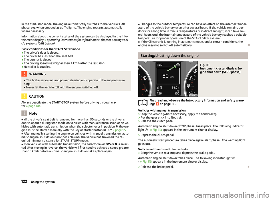
Fig. 113
Instrument cluster display: En-
gine shut down (STOP phase)
First read and observe the introductory information and safety warn-
ings on page 121.
Vehicles with manual transmission
›
Stop the vehicle (where necessary, apply the handbrake).
›
Put the gear stick into Neutral.
›
Release the clutch pedal.
Automatic engine shut down (STOP phase) takes place. The following indicator
light
- » Fig. 113 appears in the instrument cluster display.
›
Depress the clutch pedal.
The automatic start procedure takes place again (start phase). The warning light
goes out.
Vehicles with automatic transmission
›
Bring the vehicle to a stop and depress the brake pedal.
Automatic engine shut down takes place. The following indicator light
- » Fig. 113 appears in the instrument cluster display.
›
Release the brake pedal.
122Using the system
Page 126 of 222
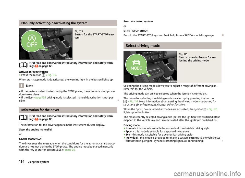
Manually activating/deactivating the systemFig. 115
Button for the START-STOP sys-
tem
First read and observe the introductory information and safety warn-
ings on page 121.
Activation/deactivation
›
Press the button
» Fig. 115 .
When start-stop mode is deactivated, the warning light in the button lights up.
Note
■ If the system is deactivated during the STOP phase, the automatic start proce-
dure takes place.■
If the Eco » page 124 driving mode is selected, manual deactivation is not pos-
sible.
Information for the driver
First read and observe the introductory information and safety warn-ings
on page 121.
The information for the driver appears in the instrument cluster display.
Start the engine manually!
or
START MANUALLY
The driver sees this message when the conditions for the automatic start proce-
dure are not met during the STOP phase. The engine must be started manually
with the key or starter button KESSY » page 95.
Error: start-stop system
or
START STOP ERROR
Error in the START-STOP system. Seek help from a ŠKODA specialist garage.
Select driving mode
Fig. 116
Centre console: Button for se-
lecting the driving mode
Selecting the driving mode allows you to adjust a range of different driving pa-
rameters for the vehicle.
The driving mode can only be selected when the ignition is turned on. The menu for selecting the driving mode is called up by pressing the button
» Fig. 116 . More information about setting the driving mode » operating in-
structions for Infotainment , chapter Other functions .
When the Sport, Eco or Individual modes are activated, the symbol
» Fig. 116
lights up in the button.
The most recently selected driving mode (before the ignition was switched off) is
mapped to the vehicle key and is re-activated after the ignition is switched on.
Driving mode
› Normal
- this mode is suitable for a standard comfortable driving style
› Sport
- this mode is suitable for a sporty driving style
› Eco
- this mode is suitable for a economical driving style
› Individual
- this mode is provided for making custom settings to the vehicle sys-
tems (steering, engine, dynamic cornering lights, air conditioning)
124Using the system
Page 132 of 222
When parking on a slope, the handbrake should be applied firmly before the park
position P is selected. This ensures that there is no excessive pressure on the
lock mechanism and that it is subsequently easier to move the selector lever out of position P.
Starting-off and driving
First read and observe the introductory information and safety warn-
ings
on page 129.
Starting off
›
Firmly depress and hold the brake pedal.
›
Press the Shiftlock button (button in the selector lever handle), move the selec-
tor lever into the desired position » page 130 and then release the Shiftlock
button.
›
Release the brake pedal and accelerate.
Stop
The selector lever position N does not have to be selected when stopping for a
short time, such as at a cross roads.
›
Fully depress and hold the brake pedal until driving is resumed.
Parking
›
Fully depress and hold the brake pedal and bring the vehicle to a stop.
›
Firmly apply the handbrake.
›
Press and Shiftlock button in the selector lever, move the selector lever to P
and then release the Shiftlock button.
Driving in Neutral
›
Select the Eco driving mode » page 124, Select driving mode .
›
Take the foot of the accelerator (selector lever in position D/S).
The vehicle moves without the braking effect of the engine.
Idling can be interrupted by briefly pressing down on the accelerator pedal or
pressing the rocker switch -
on the multifunction steering wheel
» page 131.
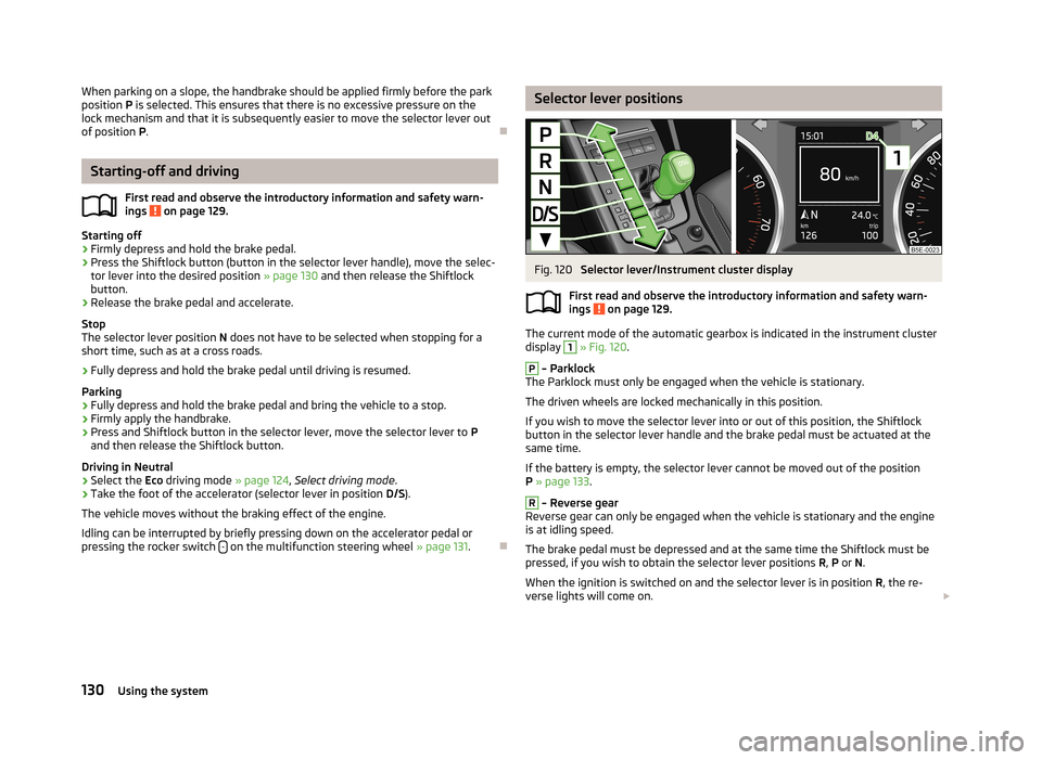
Selector lever positionsFig. 120
Selector lever/Instrument cluster display
First read and observe the introductory information and safety warn- ings
on page 129.
The current mode of the automatic gearbox is indicated in the instrument cluster display
1
» Fig. 120 .
P
– Parklock
The Parklock must only be engaged when the vehicle is stationary.
The driven wheels are locked mechanically in this position.
If you wish to move the selector lever into or out of this position, the Shiftlock
button in the selector lever handle and the brake pedal must be actuated at the
same time.
If the battery is empty, the selector lever cannot be moved out of the position
P » page 133 .
R
– Reverse gear
Reverse gear can only be engaged when the vehicle is stationary and the engine
is at idling speed.
The brake pedal must be depressed and at the same time the Shiftlock must be
pressed, if you wish to obtain the selector lever positions R, P or N.
When the ignition is switched on and the selector lever is in position R, the re-
verse lights will come on.
130Using the system
Page 187 of 222
Full wheel trimFirst read and observe the introductory information and safety warn-
ings
on page 181.
Pulling off
›
Hook the clamp found in the vehicle tool kit into the reinforced edge of the wheel trim.
›
Push the wheel wrench through the clamp, support on the tyre and pull off the
wheel trim.
Install
›
Press the wheel trim onto the wheel rim at the valve opening provided.
›
Then press the trim into the wheel rim until its entire circumference locks cor- rectly in place.
CAUTION
■ Use the pressure of your hand, do not knock the full wheel trim! Avoid heavy
knocks when the trim is not yet inserted in the wheel rim. This could cause dam-
age to the guide and centring elements of the trim.■
Ensure that the anti-theft wheel bolt has been installed correctly » page 192,
Securing wheels against theft .
■
If wheel trims are retrofitted it must be ensured that an adequate flow of air is
assured to cool the brake system.
Wheel bolts
Fig. 158
Remove the cap
First read and observe the introductory information and safety warn- ings on page 181.
Pulling off›Push the plastic clip sufficiently far onto the cap until the inner catches of the
clip are positioned at the collar of the cap » Fig. 158.›
Remove the cap.
Install
›
Push the caps onto the wheel bolts up to the stop.
The wheel bolt caps are housed in a plastic box in the spare wheel or in the stor-
age space for the spare wheel.
Tyre control display
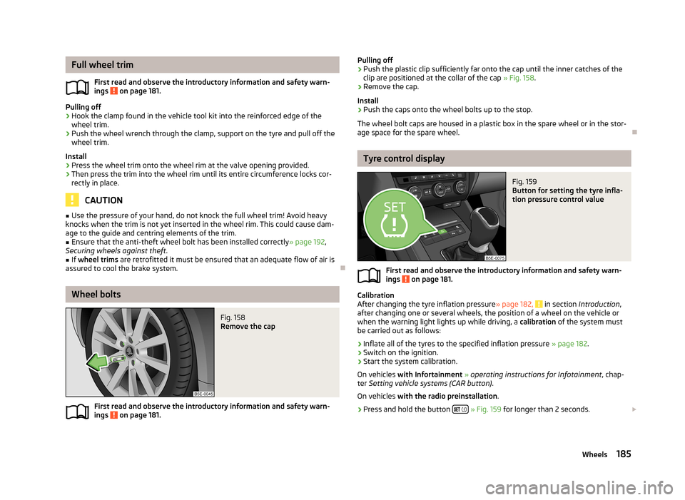
Fig. 159
Button for setting the tyre infla-
tion pressure control value
First read and observe the introductory information and safety warn-
ings on page 181.
Calibration
After changing the tyre inflation pressure » page 182, in section Introduction ,
after changing one or several wheels, the position of a wheel on the vehicle or
when the warning light lights up while driving, a calibration of the system must
be carried out as follows:
›
Inflate all of the tyres to the specified inflation pressure » page 182.
›
Switch on the ignition.
›
Start the system calibration.
On vehicles with Infortainment » operating instructions for Infotainment , chap-
ter Setting vehicle systems (CAR button) .
On vehicles with the radio preinstallation .
›
Press and hold the button
» Fig. 159 for longer than 2 seconds.
185Wheels
Page 188 of 222
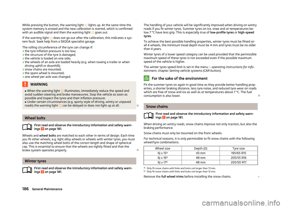
While pressing the button, the warning light lights up. At the same time the
system memory is erased and the new calibration is started, which is confirmed
with an audible signal and then the warning light goes out.
If the warning light does not go out after the calibration, this indicates a sys-
tem fault. Seek help from a ŠKODA specialist garage.
The rolling circumference of the tyre can change if: › the tyre inflation pressure is too low;
› the structure of the tyre is damaged;
› the vehicle is loaded on one side;
› the wheels of an axle are loaded heavily (e.g. when towing a trailer or when
driving uphill or downhill);
› snow chains are mounted;
› the spare wheel is mounted;
› one wheel per axle was changed.WARNING■
When the warning light illuminates, immediately reduce the speed and
avoid sudden steering and brake manoeuvres. Stop the vehicle as soon as
possible and inspect the tyres and their inflation pressure.■
Under certain circumstances (e.g. sporty style of driving, wintry or unpaved
roads) the warning light can be delayed or does not light up at all.
Wheel bolts
First read and observe the introductory information and safety warn-ings
on page 181.
Wheels and wheel bolts are matched to each other in terms of design. Each time
you fit other wheels, e.g. light alloy wheels or wheels with winter tyres, you must
also use the matching wheel bolts of the correct length and shape of spherical cap. This is essential to ensure that the wheels are tightly fitted and that the
brake system operates properly.
Winter tyres
First read and observe the introductory information and safety warn-
ings
on page 181.
The handling of your vehicle will be significantly improved when driving on wintry roads if you fit winter tyres. Summer tyres on ice, snee and at temperatures be-
low 7 °C have less grip. This is especially true of low-profile tyres or high-speed
tyres .
To achieve the best possible handling properties, winter tyres must be fitted on
all 4 wheels, the minimum tread depth must be 4 mm and tyres must be no older than 4 years.
Winter tyres of a lower speed category can be used provided that the permissible
maximum speed of these tyres is not exceeded even if the possible maximum
speed of the vehicle is higher.
The winter tyres speed limit is set in the menu » operating instructions for Info-
tainment , chapter Setting vehicle systems (CAR button) .
For the sake of the environment
Fit the summer tyres on again in good time as they provide better handling prop-
erties, a shorter braking distance, less tyre noise, and reduced tyre wear on roadswhich are free of snow and ice as well as at temperatures above 7 °C. The fuelconsumption is also lower.
Snow chains
First read and observe the introductory information and safety warn-
ings
on page 181.
When driving on wintry roads, snow chains improve not only traction, but also the
braking performance.
Snow chains must only be mounted on the front wheels.
For technical reasons, it is only permissible to fit snow chains with the following wheel/tyre combinations.
Wheel sizeDepth (D)Tyre size6J x 15 a)43 mm195/65 R156J x 16 b)48 mm205/55 R166J x 17b)48 mm205/50 R17a)
Only fit snow chains with links and locks not larger than 13 mm.
b)
Only fit snow chains with links and locks not larger than 12 mm.
Remove the full wheel trims before installing the snow chains.
186General Maintenance
Page 203 of 222
No.Power consumer
34
TCS button, ESC, tyre control display, pressure sensor for air-condi-tioning, reverse light switch, dimming rear view mirror, START-STOPbutton, telephone preinstallation, control for heating of rear seats,sensor for air-conditioning, 230 V power socket, sound actuator35Headlight, headlamp beam adjustment, diagnostic connector, camera,
radar36Headlight right37Headlight left38Towing device39Control unit for central locking front door - right, power windows -
front and rear right4012-Volt power socket41CNG relay42Control unit for central locking rear door - left, right, headlight clean-
ing system, windscreen wipers43Visor for gas discharge bulbs, interior lighting44Towing device45Control unit for control of seat adjustment46230-Volt power socket47Rear window wiper48Not assigned49Coil on starter relay, clutch pedal switch50Not assigned51Belt tensioner - front passenger side52Not assigned53Relay for rear window heater
Note
On right-hand drive vehicles, the fuse box is located on the front passenger's side
behind the stowage compartment in the left-hand section of the dash panel.
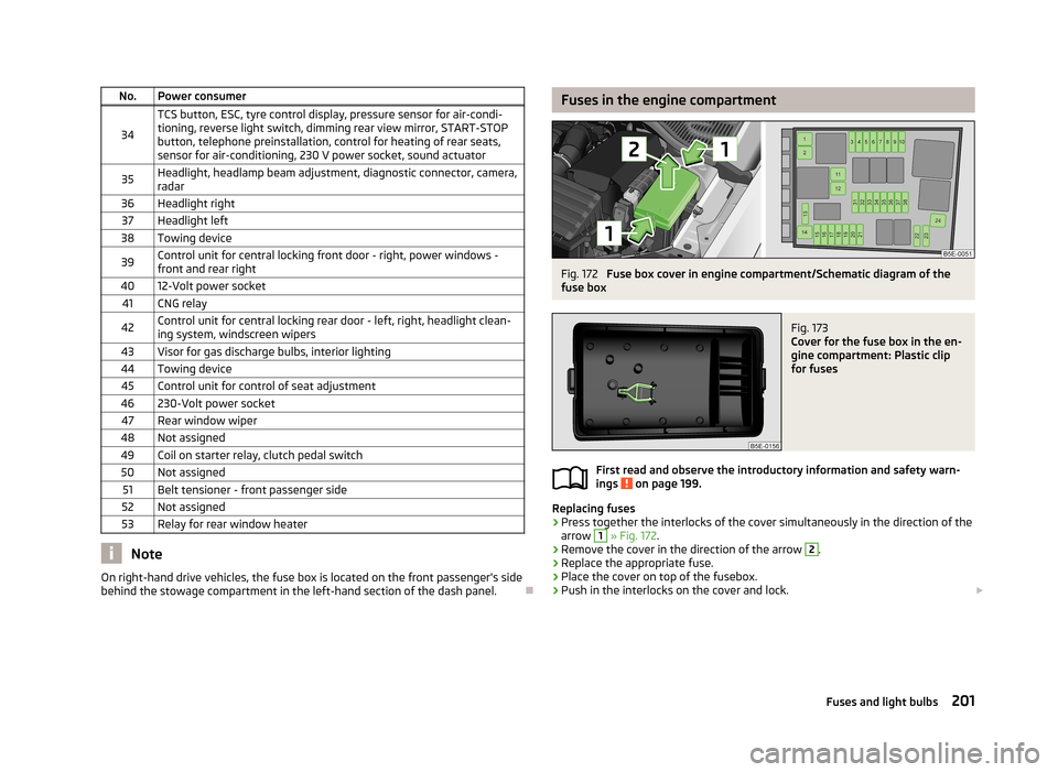
Fuses in the engine compartmentFig. 172
Fuse box cover in engine compartment/Schematic diagram of the
fuse box
Fig. 173
Cover for the fuse box in the en-
gine compartment: Plastic clip
for fuses
First read and observe the introductory information and safety warn-
ings on page 199.
Replacing fuses
›
Press together the interlocks of the cover simultaneously in the direction of the
arrow
1
» Fig. 172 .
›
Remove the cover in the direction of the arrow
2
.
›
Replace the appropriate fuse.
›
Place the cover on top of the fusebox.
›
Push in the interlocks on the cover and lock.
201Fuses and light bulbs
Page 214 of 222
Index
A
ABS Function
113
Warning light17
Accessories165
Active driver-steering recommendation (DSR)112
Adjusting Exterior mirror
58
Interior mirror57
Adjusting seats139
Adjustment Seat
60
Aerial160
see Radio reception162
Airbag146
Deployment146
Front airbag147
Head airbag150
Knee airbag148
Side airbag149
Airbag system146
Air conditioning system Air outlets
82
Climatronic86
Manual air conditioning system84
Air outlets82
Alarm35
Anti-theft alarm system35
Antilock brake system113
Armrest Front
76
rear64
Ashtray70
Assist systems ABS
17, 113
Cruise control systems (CCS)119
EDL114
ESC17, 112
Headlight assist47
Lane Assist126
Park Assist116
Parking aid114
ProActive passenger protection125
Select driving mode124
START/STOP121
TCS16, 113
Auto Check Control12
Automatic driving lamp control45
Automatic gearbox Dynamic shift programme
132
Emergency programme132
Kickdown132
Selector lever-emergency unlocking133
Selector lever lock131
Selector lever positions130
Starting-off and driving130
Tiptronic131
Automatic load deactivation180
Automatic transmission129
Auxiliary heating and cooling system Switching on/off
89
Auxiliary heating (auxiliary heating and ventila- tion)
88
setting90
B
Ball rod Check attachment
108
installing107
Ready position107
removing108
Battery Replacing the battery in the remote control(aux-
iliary heating)
91
Before setting off138
Belt tensioners145
Bonnet Closing171
Opening171
Boot Cover
67
Fastening elements65
Fixing of the floor covering66
Light65
see Boot lid37
Boot lid37
Automatic locking38
Brake booster97
Brake fluid Checking
175
Brake pads Indicator light
20
Brakes Brake assist systems
112
Brake booster97
Handbrake98
Running in100
Warning light14
Braking Brake fluid
175
Information for braking97
Breakdown kit192
Break recommendation see Fatigue detection
27
Bulbs Replacing
202
Button in the driver's door Electrical power windows
38
C
Car computer see Multifunction display
22
Car jack188
Carrier68
Catalytic converter100
Central locking button32
212Index