boot SKODA OCTAVIA 2012 3.G / (5E) Owner's Guide
[x] Cancel search | Manufacturer: SKODA, Model Year: 2012, Model line: OCTAVIA, Model: SKODA OCTAVIA 2012 3.G / (5E)Pages: 222, PDF Size: 13.52 MB
Page 79 of 222
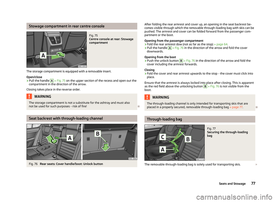
Stowage compartment in rear centre consoleFig. 75
Centre console at rear: Stowage
compartment
The storage compartment is equipped with a removable insert.
Open/close
›
Pull the handle
A
» Fig. 75 on the upper section of the recess and open out the
compartment in the direction of the arrow.
Closing takes place in the reverse order.
WARNINGThe storage compartment is not a substitute for the ashtray and must also
not be used for such purposes - risk of fire!
Seat backrest with through-loading channel
Fig. 76
Rear seats: Cover handle/boot: Unlock button
After folding the rear armrest and cover up, an opening in the seat backrest be-
comes visible through which the removable through-loading bag with skis can be
pushed. The armrest and cover can be folded forward from the passenger com-
partment or the boot.
Opening from the passenger compartment›
Fold the rear armrest dow (not as far as the stop) » page 64.
›
Pull the handle
A
» Fig. 76 in the direction of the arrow and fold the cover
downwards.
Opening from the boot
›
Push the unlock button
B
» Fig. 76 in the direction of the arrow and fold the
cover including the armrest forwards.
Closing
›
Fold the cover and rear armrest upwards to the stop - the cover must click into place.
Ensure that the armrest is always locked into place after closing. This is apparent
as the red field above the unlocking button
B
» Fig. 76 is not visible from the
boot.
WARNINGThe through-loading channel is only intended for transporting skis that are
placed in a properly secured, removable through-loading bag » page 77.
Through-loading bag
Fig. 77
Securing the through-loading
bag
The removable through-loading bag is solely used for transporting skis.
77Seats and Stowage
Page 80 of 222
Loading›Open the luggage compartment lid.›
Fold the rear armrest and the cover in the seat backrest downwards » page 77.
›
Place the empty, removable through-loading bag in such a way that the end of
the bag with the zip is in the boot.
›
Push the skis into the removable through-loading bag from the boot » .
›
Close the through-loading bag.
Securing
›
Tighten the strap
A
on the free end around the skis in front of the bind-
ings » Fig. 77 .
›
Fold the seat backrest a little forward.
›
Guide the securing strap
B
through the opening in the seat backrest around
the upper part of the seat backrest.
›
Then push the seat backrest back into the upright position until the unlocking button clicks into place - check by pulling on the seat backrest.
›
Insert the securing strap
B
into the lock
C
until it clicks into place.
WARNING■ After placing skis into the through-loading bag, you must secure the bag
with the securing strap B » Fig. 77 .■
The strap
A
must hold the skis tight.
■
Make sure that the strap
A
holds the skis in front of the binding (also refer
to imprint on the removable through-loading bag).
■
The total weight of the skis which are transported must not exceed 17 kg.
Note
■ The through-loading bag is foreseen for four pairs of skis.■Place the skis and sticks in the removable through-loading bag with the tips
facing to the rear.■
If there are several pairs of skis in the removable through-loading bag, ensure
that the bindings are positioned at the same height.
■
The removable through-loading bag must never be folded together or stowed
when moist.
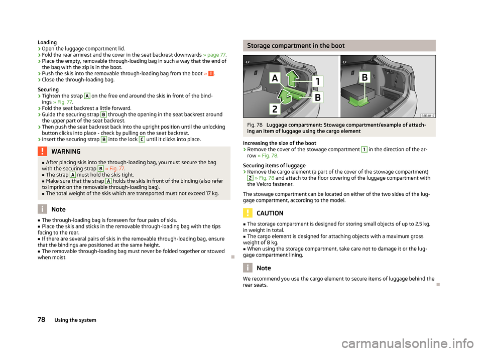
Storage compartment in the bootFig. 78
Luggage compartment: Stowage compartment/example of attach-
ing an item of luggage using the cargo element
Increasing the size of the boot
›
Remove the cover of the stowage compartment
1
in the direction of the ar-
row » Fig. 78 .
Securing items of luggage
›
Remove the cargo element (a part of the cover of the stowage compartment)
2
» Fig. 78 and attach to the floor covering of the luggage compartment with
the Velcro fastener.
The stowage compartment can be located on either of the two sides of the lug-
gage compartment, according to the model.
CAUTION
■ The storage compartment is designed for storing small objects of up to 2.5 kg.
in weight in total.■
The cargo element is designed for attaching objects with a maximum gross
weight of 8 kg.
■
When using the storage compartment, take care not to damage it or the lug-
gage compartment lining.
Note
We recommend you use the cargo element to secure items of luggage behind the
rear seats.
78Using the system
Page 108 of 222
Towing a trailer
Towing device
Introduction
This chapter contains information on the following subjects:
Description
106
Setting the ready position
107
Installing the ball rod
107
Check proper attachment
108
Removing the ball rod
108
Operation and maintenance
109
If your vehicle has already been factory-fitted with a towing device or is fitted
with a towing device from ŠKODA Original Accessories, then it meets all of the
technical requirements and national legal provisions for towing a trailer.
Your vehicle is fitted with a 13-pin power socket for the electrical connection be-tween the vehicle and trailer. If the trailer that is to be towed has a 7-pin connec-
tor , you can use a suitable adapter from ŠKODA Original Accessories.
The maximum trailer drawbar load is 75 kg/h.
WARNING■
Before each time you make a journey when using the ball rod, check that it
is seated correctly and is secured in the mounting recess.■
Do not operate the ball rod if it is not correctly inserted in the mounting re-
cess.
■
Do not operate the towing device if it is damaged or incomplete.
■
Do not perform any modifications or changes to the towing device.
■
Never release the ball rod while the trailer is still coupled.
CAUTION
■ If there is an error in the trailer lighting system, check the fuses in the fuse box
in the dashboard. » page 200■
Handle the ball rod carefully to avoid damaging the paintwork on the bumper.
Note■
After coupling the trailer and connecting up the power socket, check the rear
lights on the trailer to ensure they work.■
If you have any questions, please contact a ŠKODA Partner.
Description
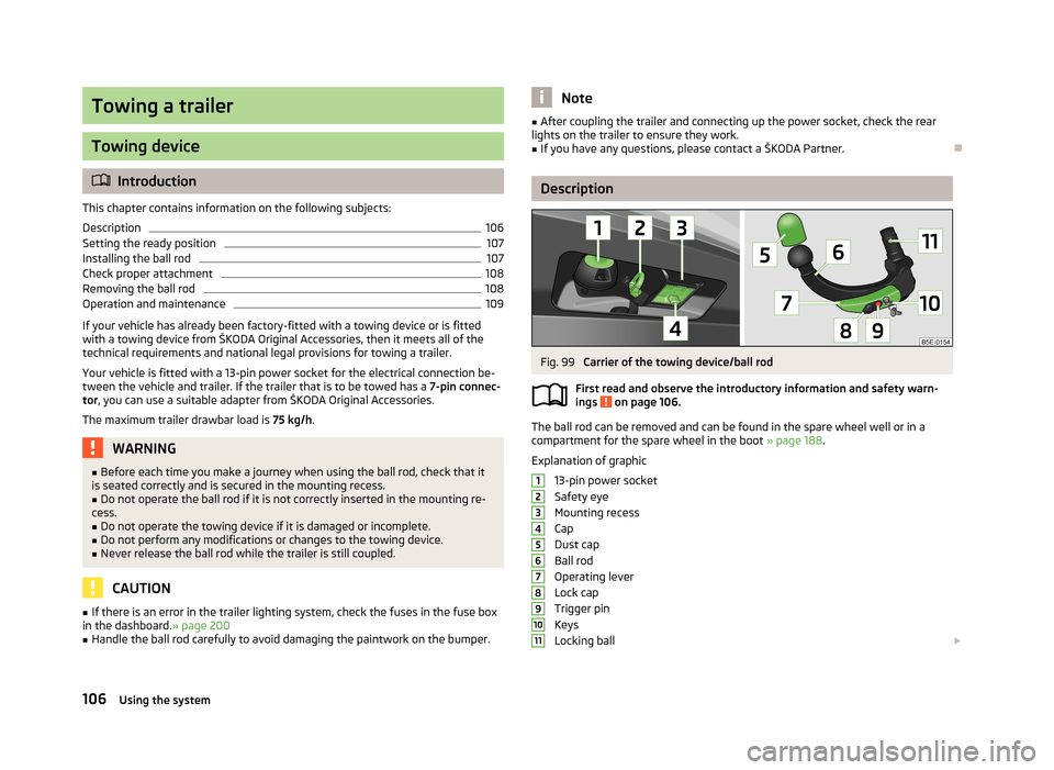
Fig. 99
Carrier of the towing device/ball rod
First read and observe the introductory information and safety warn-
ings
on page 106.
The ball rod can be removed and can be found in the spare wheel well or in a
compartment for the spare wheel in the boot » page 188.
Explanation of graphic
13-pin power socket
Safety eye
Mounting recess
Cap
Dust cap
Ball rod
Operating lever
Lock cap
Trigger pin
Keys
Locking ball
1234567891011106Using the system
Page 110 of 222

CAUTION■After removing the key, always replace the cap on the lock of the operating lev-
er - risk the lock may get contaminated.■
Keep the mounting recess of the towing device clean at all times. Such dirt pre-
vents the ball rod from being attached securely!
■
After removing the ball rod, always place the cap on the mounting recess.
Check proper attachment
Fig. 102
Check the proper attachment of
the ball rod
First read and observe the introductory information and safety warn- ings on page 106.
Before each use of the ball rod, check that it is attached properly.
Check whether:
› the lever
1
is right at the top
» Fig. 102;
› the trigger pin
2
is completely exposed (both its red and green part is visible);
› the key has been removed;
› the cap
3
is on top of the lock of the operating lever;
› after “shaking” it heavily, the ball rod does not come attached from the mount-
ing recess.
WARNINGDo not use the towing device unless the ball rod was properly locked!
Removing the ball rodFig. 103
Unlock the operating lever of the ball rod/removing the ball rod
First read and observe the introductory information and safety warn-
ings
on page 106.
›
Remove the cap
1
» Fig. 103 from the lock on the ball rod in the direction of
the arrow.
›
Unlock the lock on the operating lever by turning the key 180° to the left so that
the red marking
2
becomes visible.
›
Grab hold of the ball rod from underneath.
›
Press the trigger pin
3
as far as the stop in the direction of the arrow - at the
same time push the lever
4
downwards as far as it will go in the direction of
the arrow.
The ball rod is released in this position and falls freely into the hand. If it does not
fall freely into the hand, use your other hand to push it upwards.
At the same time, the ball rod latches into the ready position and is thus ready to
be re-inserted into the mounting recess »
.
›
Place the cap
4
» Fig. 99 on page 106 on the mounting recess.
WARNINGNever allow the ball rod to remain unsecured in the boot. This could cause
damage in a sudden braking manoeuvre and put the safety of the occupants
at risk! 108Using the system
Page 111 of 222
CAUTION■If the lever is held firm and not pushed downwards as far as it can go, it will go
back up after the ball rod is removed and will not latch into the ready position.
The ball rod then needs to be brought into this position before the next time it is installed.■
Stow the ball rod in the ready position with the key inserted in the box. When
doing so, make the side opposite to the inserted key face downwards - risk of damaging the key!
■
Do not use excessive force when handling the operating lever (e.g. do not climb
on it)!
Note
Remove any dirt from the ball rod before stowing it away in the box with the ve-
hicle tool kit.
Operation and maintenance
First read and observe the introductory information and safety warn-ings
on page 106.
Seal the mounting recess with the cap to prevent any ingress of dirt.
Always check the ball head before hitching a trailer. Use a suitable lubricating grease where necessary.
Include the protective cap when stowing away the ball rod to protect the boot
from getting contaminated.
In the event of dirt, clean the surfaces of the mounting recess and treat with a
suitable preservative.
CAUTION
Apply lubricating grease to the upper part of the mounting recess. Make sure you
do not remove any grease.
Loading a trailer
The vehicle/trailer combination must be balanced. whereby the maximum permis- sible drawbar load must be utilised. If the drawbar load is too low, it jeopardisesthe performance of the vehicle/trailer combination.
Distribution of the load
Distribute the load in the trailer in such a way that heavy items are located as
close to the axle as possible. Secure the items from slipping.
The distribution of the weight is very poor if your vehicle is unladen and the trail-
er is laden. Drive at a particularly low speed if you cannot avoid driving with this
combination.
Tyre pressure
Correct the tyre inflation pressure on your vehicle for a “full load” » page 182,
Tyre life .
Trailer load
The permissible trailer load must not be exceeded under any circumstan-
ces » page 207 , Technical data .
The trailer loads specified apply only to altitudes up to 1 000 metres above mean
sea level.
The engine output falls as the height increases, as does the ability to climb.
Therefore, for every additional 1 000 m in height (every one begun), the maximum
permissible towed weight must be reduced by 10 %.
The towed weight comprises the actual weight of the (loaded) towing vehicle and the (loaded) trailer.
The trailer and drawbar load information on the type plate of the towing device are merely test data for the towing device. The vehicle-specific values are de-tailed in the vehicle documents.WARNING■ Do not exceed the maximum permissible axle and drawbar load and the
maximum permissible total or towed weight of the vehicle and the trailer -
risk of accident and serious injuries!■
Always drive particularly carefully with the trailer.
■
Slipping loads can significantly affect the stability and safety of the vehicle/
trailer combination - risk of accident and serious injuries!
109Towing a trailer
Page 140 of 222
Safety
Passive Safety
General information
Introduction
This chapter contains information on the following subjects:
Safety equipment
138
Before setting off
138
What influences the driving safety?
139
In this section you will find important information, tips and notes on the subject
of passive safety in your vehicle. We have combined everything here which you
should be familiar with, for example, regarding seat belts, airbags, child seats and safety of children. It is therefore important, in particular, to comply with the notes
and warnings in this section for your own interest and in the interest of those
travelling with you.
WARNING■ This chapter contains important information on how to use the vehicle for
the driver and his occupants. You will find further information on safety, which concerns you and those travelling with you, in the following chapters of this
Owner's Manual.■
The complete on-board literature should always be in the vehicle. This ap-
plies in particular, if you rent out or sell the vehicle.
Safety equipment
First read and observe the introductory information and safety warn-ings
on page 138.
The following list contains part of the safety equipment in your vehicle:
› three-point seat belts for all the seats;
› belt force limiters for the front seats;
›
belt tensioners for front seats;
› seat belt height adjusters for front seats;
› Front airbag for the driver and the front seat passenger;
› driver’s knee airbag;
› front side airbags;
› rear side airbags;
› head airbags;
› anchoring points for child seat using the ISOFIX system;
› anchoring points for child seat using the TOP TETHER system;
› head restraints adjustable for height;
› adjustable steering column.
The specified safety equipment works together, in order to optimally protect you
and those travelling with you in accident situations. The safety equipment does
not protect you or the people travelling with you, if you or your occupants adopt
an incorrect seated position or the equipment is not correctly adjusted or used. If
the seat belt is not fastened properly, this may result in injuries during an acci-
dent caused by the deployed airbag.
Before setting off
First read and observe the introductory information and safety warn-
ings
on page 138.
For your own safety and the safety of the people travelling with you, please pay
attention to the following points before setting off.
› Ensure that the lighting and the turn signal system are functioning properly.
› Check the tyre inflation pressure.
› Ensure that all of the windows offer good visibility to the outside.
› Secure all items of luggage
» page 64, Boot .
› Ensure that no objects can obstruct the pedals.
› Adjust the mirrors, the front seat and head restraint to your body size.
› Advise your passengers to adjust the head restraints to their body size.
› Protect children in suitable child seats with correctly fastened seat
belts » page 154 , Transporting children safely .
› Adopt the correct seated position
» page 139, Correct seated position . Tell your
passengers to assume the correct seated position.
› Correctly fasten the seat belt. Also inform passengers to fasten the seat belt
correctly » page 142 , Seat belts .
138Safety
Page 214 of 222
Index
A
ABS Function
113
Warning light17
Accessories165
Active driver-steering recommendation (DSR)112
Adjusting Exterior mirror
58
Interior mirror57
Adjusting seats139
Adjustment Seat
60
Aerial160
see Radio reception162
Airbag146
Deployment146
Front airbag147
Head airbag150
Knee airbag148
Side airbag149
Airbag system146
Air conditioning system Air outlets
82
Climatronic86
Manual air conditioning system84
Air outlets82
Alarm35
Anti-theft alarm system35
Antilock brake system113
Armrest Front
76
rear64
Ashtray70
Assist systems ABS
17, 113
Cruise control systems (CCS)119
EDL114
ESC17, 112
Headlight assist47
Lane Assist126
Park Assist116
Parking aid114
ProActive passenger protection125
Select driving mode124
START/STOP121
TCS16, 113
Auto Check Control12
Automatic driving lamp control45
Automatic gearbox Dynamic shift programme
132
Emergency programme132
Kickdown132
Selector lever-emergency unlocking133
Selector lever lock131
Selector lever positions130
Starting-off and driving130
Tiptronic131
Automatic load deactivation180
Automatic transmission129
Auxiliary heating and cooling system Switching on/off
89
Auxiliary heating (auxiliary heating and ventila- tion)
88
setting90
B
Ball rod Check attachment
108
installing107
Ready position107
removing108
Battery Replacing the battery in the remote control(aux-
iliary heating)
91
Before setting off138
Belt tensioners145
Bonnet Closing171
Opening171
Boot Cover
67
Fastening elements65
Fixing of the floor covering66
Light65
see Boot lid37
Boot lid37
Automatic locking38
Brake booster97
Brake fluid Checking
175
Brake pads Indicator light
20
Brakes Brake assist systems
112
Brake booster97
Handbrake98
Running in100
Warning light14
Braking Brake fluid
175
Information for braking97
Breakdown kit192
Break recommendation see Fatigue detection
27
Bulbs Replacing
202
Button in the driver's door Electrical power windows
38
C
Car computer see Multifunction display
22
Car jack188
Carrier68
Catalytic converter100
Central locking button32
212Index
Page 215 of 222
Central locking system29
Changes165
Changing Engine oil
173
Wheels189
Charge level indicator of the vehicle battery
11
Charge level indicator vehicle battery
11
Charging a vehicle battery179
Checking Battery electrolyte level
179
Brake fluid175
Coolant level174
Engine oil172
Oil level172
Windscreen washer fluid176
Children and safety154
Child safety Side airbag
156
Child safety lock29
Child safety seat Use of child safety seats
156
Child seat Classification
156
ISOFIX157
on the front passenger seat155
TOP TETHER158
Use of child seats157
Chrome parts refer to Taking care of your vehicle
161
Cigarette lighter70
Cleaning159
Alcantara164
Artificial leather164
Cloths164
Headlight lenses162
Material coverings164
Natural leather164
Plastic parts162
Wheels163
Climatronic86
Clock11
Clothes hooks79
Cockpit Ashtray
70
Cigarette lighter70
General view7
Light51
Sockets71
Storage compartments72
Compartments72
Computer see Multifunction display
22
Coolant Checking
174
Replenishing175
Coolant temperature gauge display
10
Correct seated position139
Counter for distance driven11
Cruise control system (CCS)119
D
Daylight driving light
44
De-icing the windscreen and rear window52
Deactivating an airbag
151
Deactivating an airbag151
Delayed locking of the boot lid see Boot lid
38
Diesel refer to Fuel
169
Diesel fuel Operation in winter
169
Diesel particulate filter18
Digital clock11
Dipstick172
Display Service interval
11
Distance driven11
Door Child safety lock
29
Door locking Emergency
36
Doors Emergency locking
36
Driving Abroad
104
Driving through water on the street104
Emissions207
Fuel consumption207
Driving mode see Select driving mode
124
E
Economical and environmentally friendly driving
101
EDL114
Electrical power windows Button in the driver's door
38, 39
Button in the rear doors40
Central locking system40
Operational faults41
Electronic differential lock (EDL)114
Electronic immobiliser93
Emergency Automatic gearbox
133
Changing a wheel189
Door locking36
Hazard warning light system49
Jump-starting195
KESSY - start engine97
Locking the driver's door36
Towing the vehicle196
Tyre repair192
Unlocking the driver's door36
Unlocking the luggage compartment lid38
Emissions207
213Index
Page 219 of 222
Towing196
Towing a trailer106
Towing device Description
106
Drawbar load106
Towing eye front
197
Rear197
Towing protection36
Traction control system (TCS)113
Traffic sign recognition25
Traffic signs see Traffic sign recognition
25
Trailer106
13-pin power socket110
driving with a trailer110
loading109
Safety eye110
Transport Boot
64
Roof rack system68
Transporting children safely154
Two-way radio systems134
Type plate207
Tyre control display Calibration
185
Tyre load-bearing capacity see Wheels
184
Tyre repair192
Tyres see Wheels
183
U
Underbody protection
163
Unlocking Remote control
32
Unlock the vehicle Keys
31
V
Vehicle battery Automatic load deactivation
180
charging179
Checking the electrolyte level179
Operation in winter179
replacing179
Safety instructions176
Vehicle care Alcantara
164
Artificial leather164
Cloths164
Vehicle Condition see Auto Check Control
12
Vehicle data sticker207
Vehicle dimensions208
Vehicle height208
vehicle identification number - VIN (vehicle body number)
207
Vehicle key28
Vehicle length208
Vehicle tool kit188
Vehicle width208
Vest Holder for reflex vest
74
Visors see Sun screen
53
see Sun visors53
W
Warning lights
12
Warning symbols see Warning lights
12
Warning triangle188
Washing159
Automatic car wash system160
by hand160
Chrome parts161
High-pressure cleaner161
Weights207
Wheel bolts Anti-theft wheel bolt
192
Caps185
Loosening and tightening191
Wheel rims181
Wheels Bolts
186
changing189
Full trim185
General information181
Load index184
Low-profile tyres184
new tyres183
replacing wheels182
Snow chains186
Spare wheel184
Speed symbol183
Store wheels182
Tyre inflation pressure182
Tyre life182
Winter tyres186
Window Interior mirror
57
Window convenience operation40
Windows De-icing
162
See Electrical power windows38
Windscreen heating
52
see Radio reception162
Windscreen washer fluid Checking
176
Replenishing176
Warning light19
Winter176
Windscreen washer system176
Windscreen wipers54
217Index