door lock SKODA OCTAVIA 2015 3.G / (5E) Owner's Guide
[x] Cancel search | Manufacturer: SKODA, Model Year: 2015, Model line: OCTAVIA, Model: SKODA OCTAVIA 2015 3.G / (5E)Pages: 268, PDF Size: 37.54 MB
Page 96 of 268
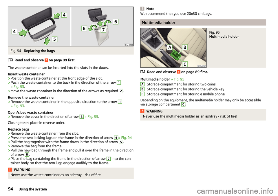
Fig. 94
Replacing the bags
Read and observe
on page 89 first.
The waste container can be inserted into the slots in the doors.
Insert waste container
›
Position the waste container at the front edge of the slot.
›
Push the waste container to the back in the direction of the arrow
1
» Fig. 93 .
›
Move the waste container in the direction of the arrows as required
2
.
Remove the waste container
›
Remove the waste container in the opposite direction to the arrow
1
» Fig. 93 .
Open/close waste container
›
Remove the cover in the direction of arrow
3
» Fig. 93 .
Closing takes place in reverse order.
Replace bags
›
Remove the waste container from the slot.
›
Press the two locking lugs on the frame in the direction of arrow
4
» Fig. 94 .
›
Pull the bag together with the frame down in the direction of arrow
5
.
›
Remove the bag from the frame.
›
Pull the new bag through the frame and pull it over the frame in the direction
of arrow
6
.
›
Place the bag containing the frame in the direction of arrow
7
into the con-
tainer body, so that the two lugs engage audibly to the frame.
WARNINGNever use the waste container as an ashtray - risk of fire!NoteWe recommend that you use 20x30 cm bags.
Multimedia holder
Fig. 95
Multimedia holder
Read and observe on page 89 first.
Multimedia holder » Fig. 95
Storage compartment for storing two coins
Storage compartment for storing the vehicle key
Storage compartment for storing a mobile phone
Depending on the equipment, the multimedia holder may only be accessible
via storage compartment
C
.
WARNINGNever use the multimedia holder as an ashtray - risk of fire!ABC94Using the system
Page 112 of 268
If the crossbar is hooked into the receptacle E to the left for example, then
press on the crossbar in the direction of the arrow 1 and insert into the re-
ceptacle E
to the right.
›
Make sure that the crossbar is firmly seated in the fittings
E
.
›
Fold back part of the roll-up luggage compartment cover
A
in the opposite
direction of the arrow » Fig. 130.
Using the net partition behind the rear seats
›
Fold out part of the roll-up luggage compartment cover
A
in the direction of
the arrow » Fig. 130.
›
Press on the crossbar and remove it from the receptacles
E
, first on one
side, then on the other side » Fig. 131.
›
Hold the crossbar
C
in such a way that the net partition can slowly roll up
into the housing
D
without being damaged.
›
Fold back part of the roll-up luggage compartment cover
A
in the opposite
direction of the arrow » Fig. 130.
CAUTION
If the net partition blocks when pulling it out of the housing, push the release
lever B in the direction of the arrow » Fig. 130.
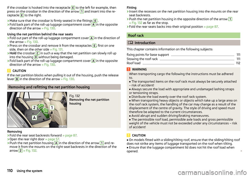
Removing and refitting the net partition housing
Fig. 132
Removing the net partition
housing
Removing
›
Fold the rear seat backrests forward » page 87.
›
Open the rear right door » page 57.
›
Push the net partition housing
A
in the direction of the arrow
1
and re-
move it from the mounts on the right seat backrests in the direction of the
arrow
2
» Fig. 132 .
Fitting›Insert the recesses on the net partition housing into the mounts on the rear
seat backrests.›
Push the net partition housing in the opposite direction of the arrow
1
» Fig. 132 as far as the stop.
›
Fold the rear seats backs into their original position » page 87.
Roof rack
Introduction
This chapter contains information on the following subjects:
fixing points for base support
111
Stowing the roof rack
111
Roof load
112WARNINGWhen transporting cargo the following the instructions must be adhered
to.■
The transported items on the roof rack must always be securely attached
– risk of accident!
■
Always secure the load with appropriate and undamaged lashing straps
or tensioning straps.
■
Distribute the load evenly over the roof rack system.
■
When transporting heavy objects or objects which take up a large area on
the roof rack system, the handling of the car may change as a result of the
displacement of the centre of gravity. The style of driving and speed must
therefore be adapted to the current circumstances.
■
Avoid abrupt and sudden driving/braking manoeuvres.
■
The permissible roof load, permissible axle loads and gross permissible
weight of the vehicle must not be exceeded under any circumstances – risk
of accident!
CAUTION
■ On models fitted with a sliding/tilting roof, ensure that the sliding/tilting roof
does not strike any items of luggage transported on the roof when tilting.■
Ensure that the luggage compartment lid does not hit the roof load when
opened.
110Using the system
Page 124 of 268

Starting and stopping the engine at the push of the button
Introduction
Fig. 143
Starter button (
)
This chapter contains information on the following subjects:
Steering column lock locking / unlocking
122
Switching ignition on / off
123
Starting the engine
123
Switching off the engine
123
Problems starting the engine
124
The ignition can be switched on and off and the engine can be started/stop-
ped with the starter button » Fig. 143.
The key must be in the vehicle in order to unlock the steering wheel, switch on the ignition, start the engine and drive.
WARNING■ Never leave the key in the vehicle when you exit the vehicle. Unauthor-
ized persons such as children could lock the car, turn on the ignition or start
the engine -risk of injury, accidents and damage!■
Never leave the vehicle unattended with the engine running - there is a
risk of theft etc!
■
Never switch off the engine before the vehicle is stationary – risk of acci-
dent!
WARNINGNever (e.g. in garages) run the engine in a closed place - there is the danger
of poisoning and death!CAUTION■ The system can recognize the valid key, even if it has been accidentally left
on the vehicle roof - there is danger of loss or damage to the key!■
Only start the engine when the engine and the vehicle are stationary - there
is a danger of starter and engine damage!
■
Do not push-start the engine – there is a risk of damaging the engine and
the catalytic converter. The battery from another vehicle can be used as a
jump-start aid » page 219.
Note
■
Do not warm up the engine while the vehicle is stationary. If possible, start
your journey as soon as the engine has started. Through this, the engine rea-
ches its operating temperature faster.■
The system is protected against inadvertently switching off the engine while
driving, this means that the engine can only be switched off in an emergency
» page 123 .
Steering column lock locking / unlocking
Read and observe
and on page 122 first.
The steering lock (steering lock) deters any attempted theft of your vehicle.
Locking
›
Switch off the engine.
›
Open the driver door.
The steering lock is locked automatically.
If the driver's door is opened and the ignition is switched off afterwards, the
steering is only locked after the vehicle has been locked.
Unlocking
›
Open the driver's door and get into the vehicle.
›
Close the driver's door.
The steering is locked automatically.
Under certain circumstances (e.g. after switching off the ignition and opening
the driver's door), the steering is enabled only when the ignition is switched on
or the engine is started.
122Driving
Page 125 of 268
WARNINGNever let the vehicle roll with locked steering lock - there is a risk of acci-
dent!
Switching ignition on / off
Read and observe
and on page 122 first.
›
Press the button » Fig. 143 on page 122 briefly.
The ignition is switched on or off.
On vehicles fitted with a manual gearbox, the clutch pedal must not be de-
pressed while switching the ignition on or off, otherwise the system would try
to start.
On vehicles fitted with a automatic gearbox, the brake pedal must not be de-
pressed while switching the ignition on or off, otherwise the system would try
to start.
If the driver's door is opened while the ignition is on, an audible signal sounds
and the following message appears in the instrument cluster display.
Ignition switched on.IGNITION STILL ON
When leaving the vehicle always switch off the ignition.
Starting the engine
Read and observe
and on page 122 first.
Procedure for starting the engine
›
Firmly apply the handbrake.
›
For vehicles with manual transmission , shift gear stick to neutral, depress
the clutch pedal and hold it there until the engine starts.
›
On vehicles with automatic transmission , place the selector lever in position
P or N and depress the brake pedal until the engine starts.
›
Press the starter button » Fig. 143 on page 122 briefly – the engine starts au-
tomatically.
In vehicles with diesel engines after pressing the button, the glow plug warn-
ing light lights up. The engine starts after the warning light goes out.
Note■
The engine running noises may louder at first be louder for a short time after
starting the cold engine. This is quite normal and is not an operating problem.■
You should not switch on any major electrical components during the heat-
ing period otherwise the vehicle battery will be drained unnecessarily.
Switching off the engine
Read and observe
and on page 122 first.
Switching off
›
Stop the vehicle » page 128, Parking .
›
Press the button » Fig. 143 on page 122 briefly.
The engine and the ignition are switched off simultaneously.
Emergency shut-down
If necessary and in exceptional cases, the engine may even be turned off while
driving.
›
Press the starter button » Fig. 143 on page 122 for longer than 1 second or
twice within 1 second.
After the emergency stop of the engine, the steering lock will remain un-
locked.
CAUTION
Do not switch the engine off immediately at the end of your journey after the
engine has been operated over a prolonged period at high loads but leave it to
run at an idling speed for about 1 minute. This prevents any possible accumula-
tion of heat when the engine is switched off.
Note
After switching off the ignition, the radiator fan may intermittently continue to
operate for approx. 10 minutes.123Starting-off and Driving
Page 131 of 268
In the driver's footwell, only a footmat, which is attached to the two corre-
sponding attachment points may be used.
Only use factory-supplied footmats or footmats from the range of ŠKODAOrigi-
nal Accessories, which are fitted to two attachment points.WARNINGNo objects may be placed in the driver's footwell – risk due to obstruction
or limitation of pedal operation.
Automatic gearbox
Introduction
This chapter contains information on the following subjects:
Modes and use of selector lever
129
Selector lever lock
130
Manual shifting of gears (Tiptronic)
130
Starting-off and driving
131
The automatic transmission performs automatic gear changes.
The modes of the automatic transmission can be adjusted by the driver by
means of the selector lever.
WARNING■ No throttle when it is set before starting the mode for moving forward
with the selector lever - there is a risk of accident!■
Never move the selector lever to mode R or P when driving – risk of an
accident!
■
If the vehicle is in the mode selected D, S , R or Tiptronic and the engine
stops when at idle speed, then the brake pedal must be pressed. Even
when the engine is idling, the power transmission is never completely in-
terrupted – the vehicle creeps.
■
When leaving the vehicle, the selector lever is always to put in the P
mode. Otherwise, the vehicle could be set in motion - risk of accident!
CAUTION■ If the selector lever is moved to mode N while driving, the accelerator pedal
must be released and you will need to wait until the engine has reached its
idling speed before moving the selector lever to a forward driving mode again.■
When the outdoor temperature is below -10 ° C, the selector lever when
starting must always be in P mode.
■
When stopping on a slope, never try to hold the vehicle using the accelerator
pedal – this may lead to gear damage.
Note
After the ignition is switched off, the ignition key can only be withdrawn if the
selector lever is in the position P.
Modes and use of selector lever
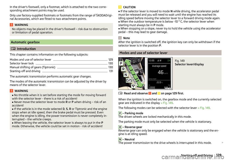
Fig. 149
Selector lever/display
Read and observe and on page 129 first.
When the ignition is switched on, the gearbox mode and the currently selected
gear are indicated in the display » Fig. 149.
The following modes can be selected with the selector lever » Fig. 149.
P
– Parking mode
The driven wheels are locked mechanically in this mode.
The parking mode must only be selected when the vehicle is stationary.
R
– Reverse gear
Reverse gear can only be engaged when the vehicle is stationary and the en-
gine is at idling speed.
N
– Neutral
The power transmission to the drive wheels is interrupted in this mode.
129Starting-off and Driving
Page 139 of 268
During a TCS intervention, the indicator light flashes in the instrument clus-
ter.
Activating/deactivating TCS
The activation or deactivation of TCS can be done, depending on equipment, in
one of the following ways. ▶ Infotainment » Owner´s Manual Infotainment , chapter CAR - vehicle set-
tings .
▶ By briefly pressing the symbol key
» Fig. 155 .
▶ By briefly pressing the symbol key
» Fig. 155 .
Upon deactivation, in the instrument cluster the indicator light
lights up and
the display shows the following message.Traction control (ASR) deactivated.ASR OFF
Upon activation, in the instrument cluster the indicator turns and the display
shows the following message.
Traction control (ASR) activated.ASR ON
The TCS should normally always be enabled. The system should be deactivated
only in the following situations, for example. ▶ When driving with snow chains.
▶ When driving in deep snow or on a very loose surface.
▶ When it is necessary to “rock” a car free when it has become stuck.
Note
On vehicles without the ESC system, the warning light does not illuminate
upon deactivation of the TCS system, but a message is only displayed on the
display of the instrument cluster.
Electronic differential lock (EDL and XDS)
Read and observe
on page 136 first.
EDL
EDL prevents the turning of the respective wheel of the driven axle. EDL
brakes the spinning wheel, if necessary, and transmits the driving force to the
other driving wheel. Driving becomes easier on road surfaces with different
traction under each wheel of the driven axle.
EDL switches off automatically to avoid excessive heat generation on the
brake of the wheel being braked. Once the brakes have cooled down, there is
an automatic re-activation of EDL.
XDS
XDS is an extension to the electronic differential lock. XDS does not respond to
traction, but to the load relief of the inner front wheel of the driving axle dur-
ing fast cornering.
The automatic brake intervention on the brake of the wheel with reduced load
prevents the wheel from spinning. Thus, the traction is improved and the vehi-
cle can continue to follow the desired track.
Driver Steering Recommendation (DSR)
Read and observe
on page 136 first.
The DSR indicates to the driver in critical situations a steering recommenda-
tion in order to stabilise the vehicle. The DSR is activated, for example, on the
right and left vehicle side when braking sharply on different road surfaces.
Brake Assist (HBA)
Read and observe
on page 136 first.
HBA increases the braking effect and helps to shorten the braking distance.
The HBA is activated by the very quick operation of the brake pedal. To ach-
ieve the shortest possible braking distance, the brake pedal must be applied
firmly until the vehicle has come to a complete standstill.
The HBA is automatically switched off when the brake pedal is released.
Hill Start Assist (HHC)
Read and observe
on page 136 first.
HHC allows you, when driving on slopes, to move your foot from the brake
pedal to the accelerator pedal without having to use the handbrake.
The system holds the brake pressure produced by the activation of the brake pedal for approx. 2 seconds after the brake pedal is released.
The HHC is active from a 5% slope if the driver's door is closed. HHC is always
active on slopes when in forward or reverse start off.
137Assist systems
Page 184 of 268
Clean wheels, door sills and similar parts last. Use a second sponge for such
areas.
Give the vehicle a good rinse after washing it and dry it off using a chamois
leather.WARNINGProtect your hands and arms from sharp-edged metal parts when cleaning
the underfloor or the inside of the wheel housings or the wheel trims – risk
of cuts!
CAUTION
■ Only apply slight pressure when cleaning the vehicle's paintwork.■Do not wash your vehicle in bright sunlight – risk of paint damage.
Automatic car wash systems
Read and observe
and on page 181 first.
The usual precautionary measures must be taken before washing the vehicle
in an automatic car wash system (e.g. closing the windows and the sliding/tilt-
ing roof etc.).
If your vehicle is fitted with any particular attached parts, such as a spoiler,
roof rack system, two-way radio aerial etc., it is best to consult the operator of
the car wash system beforehand.
After an automatic wash with wax treatment, the lips of the wipers should be
cleaned with cleaning agents specially designed for the purpose, and then de-
greased.
CAUTION
Before driving through a car wash fold in the exterior mirrors - there is a risk of
damage.
Washing with a high-pressure cleaner
Read and observe
and on page 181 first.
When washing the vehicle with a high-pressure cleaner, the instructions for
use of the equipment must be observed. This applies in particular to the pres-
sure used and to the spraying distance .
Maintain a sufficiently large distance to the parking aid sensors and soft mate-
rials such as rubber hoses or insulation material.
CAUTION
■ The films should not be washed with any high-pressure cleaners - there is a
risk of damage » page 183.■
Do not aim the water jet directly at the lock cylinders or the door or opening
joints when washing the vehicle in the winter – there is a risk of freezing.
■
The sensors of the parking aid can be sprayed only for a short time and there
must be a minimum distance of 10 cm - there is a risk of damage.
Cleaning vehicle exterior
Introduction
This chapter contains information on the following subjects:
Vehicle paint work
183
Films
183
Plastic parts
184
Rubber seals
184
Chrome and anodized parts
184
Windows and external mirrors
184
Headlight glasses
185
Camera lens
185
Door closing cylinder
185
Cavity protection
185
Jack
185
Wheels
185
Towing hitch and mounting recess
186
Under-body protection
186
Wiper blades
186
We recommend using vehicle care products from ŠKODA Original Accessories.
These are available from ŠKODA Partners. The usage instructions on the pack-
age must be observed.
182General Maintenance
Page 187 of 268

CAUTIONInformation for cleaning windows■Do not clean the inside of the windows with sharp-edged objects or corro-
sive and acidic cleaning agents – there is a risk of damaging the heating ele-
ments or window aerial.■
When drying the windows after washing the vehicle, do not use window
leathers that have been used to polish the bodywork. Residues of preserva-
tives in the window leather can dirty the window and reduce visibility.
Headlight glasses
Read and observe
and on page 183 first.
Clean plastic front headlight lenses using clean, warm water and soap.
CAUTION
■The headlights are never to be wiped dry - there is a risk of damaging the
protective lacquer and the headlight glass subsequently developing cracks.■
Do not use sharp objects to clean the glasses - there is a risk of damaging
the protective lacquer and the headlight glasses subsequently developing
cracks.
■
Do not use any aggressive cleaning or chemical solvent products to clean the
headlights – risk of damaging the headlight lenses.
Camera lens
Read and observe
and on page 183 first.
Moisten the lens of the rear view camera first with clean water and then dry
with a dry cloth.
Remove the snow from the lens with a brush and the ice from the lens with
de-icing agents specifically developed for these purposes.
CAUTION
■ Remove snow or ice on the lens with warm or hot water - there is a risk of
damaging the lens.■
Never use cleaners containing abrasive effect to clean the lens.
■
Never use pressurized water or steam jet to clean the lens.
Door closing cylinder
Read and observe
and on page 183 first.
Specific products must be used for de-icing door lock cylinders.
CAUTION
Make sure that as little water as possible gets into the locking cylinder when
washing the vehicle - there is a risk of freezing the lock cylinder!
Cavity protection
Read and observe
and on page 183 first.
All the cavities of your vehicle which are at risk from corrosion are protected
for life by a layer of protective wax applied in the factory.
Wax protection does not require to be inspected or re-treated.
If any small amount of wax flow out of the cavities at high temperatures, these
must be removed with a plastic scraper and the stains cleaned using a petrole-
um cleaner.
WARNINGSafety regulations should be observed when using petroleum cleaner to re-
move wax – risk of fire!
Jack
Read and observe
and on page 183 first.
The jack is maintenance-free.
If necessary, the moving parts of the jack should be lubricated with a suitable
lubricant.
Wheels
Read and observe
and on page 183 first.
Wheel rims
Also thoroughly wash the wheel rims when washing the vehicle on a regular
basis.
185Care and maintenance
Page 194 of 268
Preheating fuel
The vehicle is fitted with a fuel filter preheating system. This secures opera-
tion of a vehicle using diesel fuel down to an environmental temperature of
-24 °C.
Diesel fuel additives
The diesel fuel in accordance with the prescribed standards meets all the con-
ditions for a smooth running engine. We therefore recommend that no diesel
fuel additives are used. This can result in considerable damage to parts of the
engine or the exhaust system.
CAUTION
■ Just filling the tank once with diesel fuel that does not comply with the
standard, can cause severe damage to parts of the engine, the fuel and ex-
haust system.■
If a different fuel other than diesel fuel, which complies to the above men-
tioned standards (e.g. petrol) is used, do not start the engine or switch on the
ignition! Extensive damage to engine parts can occur.
■
Water which has collected in the fuel filter can cause engine faults.
CAUTION
■ The vehicle cannot be operated with bio fuel RME, therefore this fuel must
not be filled in the tank and used for driving the vehicle. The use of biofuel
RME can cause considerable damage to parts of the engine or fuel system.■
Do not mix any fuel additives, so-called “flow improvers” (petrol and similar
agents) into the diesel. This can result in considerable damage to parts of the
engine or the exhaust system.
Refuelling with CNG (compressed natural gas)
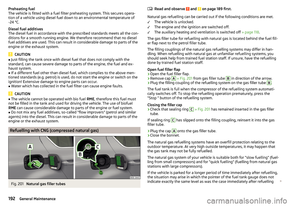
Fig. 201
Natural gas filler tubes
Read and observe and on page 189 first.
Natural gas refuelling can be carried out if the following conditions are met.
The vehicle is unlocked.
The engine and the ignition are switched off.
The auxiliary heating and ventilation is switched off » page 118.
The gas filler tube for refuelling with natural gas is located behind the fuel fill-
er flap next to the petrol filler tube.
The filling couplings of the natural gas refuelling systems may differ in han-
dling. When refuelling with natural gas at unfamiliar refuelling systems, you
should seek help from trained fuel station staff. If unsure, have the refuelling
done by trained fuel station staff.
Open fuel filler flap
›
Open the fuel filler flap.
›
Remove cap
A
» Fig. 201 from gas filler tube
B
in direction of the arrow.
›
Plug the filling coupling of the refuelling system on the gas filler tube
B
.
The fuel tank is full when the compressor of the refuelling system automati-
cally switches off. To stop the refuelling operation prematurely, press the
“Stop ” button of the refuelling system.
Closing the filler cap
›
Check that sealing ring
C
» Fig. 201 has remained inserted in the gas filler
tube.
If sealing ring
C
has slipped onto the filling coupling, reinsert it into the gas
filler tube.
›
Plug the cap
A
onto the gas filler tube.
›
Close the bonnet.
The natural gas refuelling systems have an overfill protection relating to the
outdoor temperature. At very high outside temperatures, it may happen that
the gas tank may not be fully refuelled.
The natural gas system of your vehicle is suitable both for “slow fuelling” (fuel-
ling from small compressors) and for “quick fuelling” (fuelling from natural gas
stations with large compressors).
If the vehicle is parked for a longer period of time immediately after refuelling,
the situation may arise in which the pointer of the fuel tank gauge does not
indicate exactly the same level as was the case immediately after refuelling
192General Maintenance
Page 197 of 268
WARNING (Continued)■Never spill operating fluids over the hot engine - risk of fire.■If you wish to work under the vehicle, you must secure the vehicle from
rolling away and support it with suitable supporting blocks: the car jack is
not sufficient for this – risk of injury!
CAUTION
Always top up using the correct specification of fluids. This may result in major
operating problems and also vehicle damage!
For the sake of the environment
In view of the requirements for the environmentally friendly disposal of fluids and the special tools and knowledge required for such work, we recommend
that fluids be changed by a specialist garage.
Note
■ Please consult a specialist garage for any questions relating to fluids.■Fluids with the proper specifications can be purchased from the ŠKODA Origi-
nal Accessories or from the ŠKODA Genuine Parts ranges.
Opening and closing the bonnet
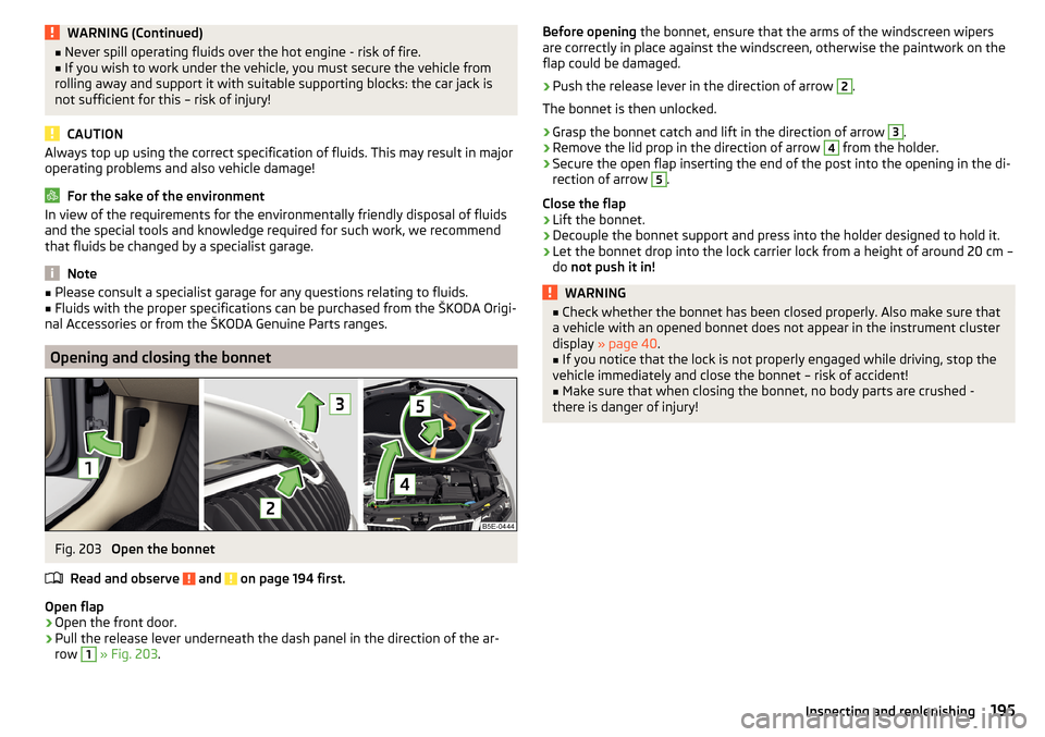
Fig. 203
Open the bonnet
Read and observe
and on page 194 first.
Open flap
›
Open the front door.
›
Pull the release lever underneath the dash panel in the direction of the ar-
row
1
» Fig. 203 .
Before opening the bonnet, ensure that the arms of the windscreen wipers
are correctly in place against the windscreen, otherwise the paintwork on the
flap could be damaged.›
Push the release lever in the direction of arrow
2
.
The bonnet is then unlocked.
›
Grasp the bonnet catch and lift in the direction of arrow
3
.
›
Remove the lid prop in the direction of arrow
4
from the holder.
›
Secure the open flap inserting the end of the post into the opening in the di-
rection of arrow
5
.
Close the flap
›
Lift the bonnet.
›
Decouple the bonnet support and press into the holder designed to hold it.
›
Let the bonnet drop into the lock carrier lock from a height of around 20 cm – do not push it in!
WARNING■
Check whether the bonnet has been closed properly. Also make sure that
a vehicle with an opened bonnet does not appear in the instrument cluster
display » page 40 .■
If you notice that the lock is not properly engaged while driving, stop the
vehicle immediately and close the bonnet – risk of accident!
■
Make sure that when closing the bonnet, no body parts are crushed -
there is danger of injury!
195Inspecting and replenishing