oil SKODA OCTAVIA 2015 3.G / (5E) Owner's Guide
[x] Cancel search | Manufacturer: SKODA, Model Year: 2015, Model line: OCTAVIA, Model: SKODA OCTAVIA 2015 3.G / (5E)Pages: 268, PDF Size: 37.54 MB
Page 199 of 268
CAUTION■Under no circumstances must radiator antifreeze or other additives be added
to the windscreen washer fluid.■
If the vehicle is fitted with a headlight cleaning system, only cleaning prod-
ucts which do not attack the polycarbonate coating of the headlights must be
added to the windscreen washer fluid.
■
Do not remove the filter from the windscreen washer fluid reservoir when re-
plenishing it with liquid otherwise the liquid transportation system can be con-
taminated, which can cause the windscreen washer system to malfunction.
Engine oil
Introduction
This chapter contains information on the following subjects:
Specification
197
Checking the oil level
198
Replenishing
198
The engine has been factory-filled with a high-grade oil that can be use
throughout the year - except in extreme climate zones.
The engine oils are undergoing continuous further development. Thus the in- formation stated in this Owner's Manual is only correct at the time of publica-
tion.
ŠKODA Service Partners are informed about the latest changes by the manu-
facturer. We therefore recommend that the oil change be completed by a
ŠKODA Service Partner.
The specifications (VW standards) stated in the following can be indicated sep-
arately or together with other specifications on the bottle.
The engine oil should be changed after specified service intervals » page 49.
WARNINGThe engine compartment of your car is a hazardous area. The following
warning instructions must be followed at all times when working in the en-
gine compartment » page 194.
CAUTION
Do not pour any additives into the engine oil – risk of serious damage to the
engine parts.Note■ Before a long drive we recommend that you purchase and carry with you en-
gine oil which complies with the specification for your vehicle.■
We recommend that you use oils from ŠKODA Original Accessories.
■
If your skin has come into contact with oil, it must be washed thoroughly.
Specification
Read and observe
and on page 197 first.
Vehicles with variable service intervals
Petrol enginesSpecification1.2 l/63, 81 kW TSI
VW 504 00
1.4 l/110 kW TSI1.8 l/132 kW TSI2.0 l/162, 169 kW TSIDiesel engines a)Specification1.6 l/66, 81 kW TDIVW 507 002.0 l/105, 110, 135 kW TDIa)
Engine oil VW 505 01 can optionally be used in diesel engines without a
DPF.
Vehicles with fixed service intervals
Petrol enginesSpecification1.2 l/63, 81 kW TSI
VW 502 00
1.4 l/81 kW TSI G-TEC1.4 l/110 kW TSI1.6 l./81 kW MPI1.8 l/132 kW TSI2.0 l/162, 169 kW TSIDiesel engines a)Specification1.6 l/66, 81 kW TDIVW 507 002.0 l/105, 110, 135 kW TDIa)
Engine oil VW 505 01 can optionally be used in diesel engines without a
DPF.
197Inspecting and replenishing
Page 200 of 268

CAUTION■In an emergency, another engine oil to be refilled. To prevent damage to the
engine, a maximum of 0.5 litres only of the following engine oils may be used:
■ For petrol engine models: ACEA A3/ACEA B4 or API SN, (API SM);
■ For diesel engine models: ACEA C3 or API CJ-4.
Checking the oil level
Fig. 206
Principle sketch: Dipstick
Read and observe
and on page 197 first.
The dipstick indicates the engine oil level .
Dipstick » Fig. 206
The oil level must be within this range.
The oil can be checked and topped up, if the following conditions are satisfied. The vehicle is on a horizontal surface.
The engine operating temperature is reached.
The engine is turned off.
The bonnet is open.
Checking the level
›
Wait a few minutes until the engine oil flows back into the oil trough.
›
Pull out the dipstick.
›
Wipe the dipstick with a clean cloth and insert it again to the stop.
›
Pull the dipstick out again and check the oil level.
›
Re-insert the dipstick.
AThe engine consumes a little oil. The oil consumption may be as much as 0.5
l/1000 km depending on your style of driving and the conditions under which
you operate your vehicle. Consumption may be slightly higher than this during
the first 5 000 km.
The oil level must be checked at regular intervals.
In case of low oil level, the instrument cluster display shows a warning light
as well as the relevant notification » page 38. Check the oil level using the dip-
stick as soon as possible. Add oil accordingly.
CAUTION
■ The oil level must never be above the range A » Fig. 206 - risk of damage to
the motor as well as the exhaust system.■
If for some reason it is not possible to top up the engine oil under the current
circumstances,
do not continue driving! Switch off the engine and seek as-
sistance from a specialist garage.
■
If the oil level is above level
A
,
do not continue to drive! Switch off the
engine and seek assistance from a specialist garage.
Replenishing
Read and observe
and on page 197 first.
›
Unscrew the cap of the engine oil filler opening » Fig. 204 on page 196 .
›
Replenish the oil in portions of 0.5 litres in accordance with the correct speci-
fications » page 197 .
›
Check the oil level » page 198.
›
Screw the lid of the engine oil filler closed carefully.
›
Pull the dipstick out as far as the stop.
Coolant
Introduction
This chapter contains information on the following subjects:
Checking the coolant level
199
Replenishing
200
The coolant provides cooling for the motor.
It consists of water and coolant additive with additives that protect the cooling
system against corrosion and prevents furring.
198General Maintenance
Page 209 of 268
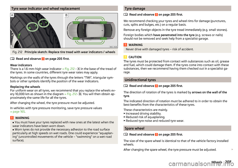
Tyre wear indicator and wheel replacementFig. 212
Principle sketch: Replace tire tread with wear indicators / wheels
Read and observe
on page 205 first.
Wear indicators
There is a 1.6-mm-high wear indicator » Fig. 212 -
in the base of the tread of
the tyres. In some countries, different tyre wear rates may apply.
Markings on the walls of the tyres through the letters “TWI”, triangular sym- bols or other symbols identify the position of the wear indicators.
Replacing the wheels
For uniform wear on all tyres, we recommend that you replace the wheels ev-
ery 10,000 km as shown in the diagram » Fig. 212-
. You will then obtain ap-
proximately the same life for all the tyres.
After changing the wheel, the tyre pressure must be adjusted.
In vehicles with tyre pressure monitoring, save tyre pressure values
» page 165 .
WARNING■
You must have your tyres replaced with new ones at the latest when the
wear indicators have been worn down.■
Worn tyres do not provide the necessary adhesion to the road surface
particularly at high speeds on wet roads. One could experience “aquaplan- ing” (uncontrolled movements of the vehicle – “swimming” on a wet road surface).
Tyre damage
Read and observe
on page 205 first.
We recommend checking your tyres and wheel rims for damage (punctures,
cuts, splits and bulges, etc.) on a regular basis.
Remove any foreign objects in the tyre tread immediately (e.g. small stones).
Foreign bodies which have penetrated into the tyre (e.g. screws or nails)
should not be removed and seek help from a specialist garage.
WARNINGNever drive with damaged tyres – risk of accident.
CAUTION
The tyres must be protected from contact with substances such as oil, grease
and fuel, which could damage them. If the tyres come into contact with these
substances, then we recommend having them checked out in a specialist ga-
rage.
Unidirectional tyres
Read and observe
on page 205 first.
The direction of rotation of the tyres is marked by arrows on the wall of the
tyre .
The indicated direction of rotation must be adhered to in order to obtain the
best benefits from the characteristics of these tyres.
These characteristics are mainly.
▶ Increased driving stability.
▶ Reduced risk of aquaplaning.
▶ Reduced tyre noise and reduced tyre wear.
Spare wheel
Read and observe
on page 205 first.
The size of the spare wheel is identical to that of the vehicle factory installedwheels.
After changing the spare wheel, the tyre pressure must be adjusted.
207Wheels
Page 218 of 268
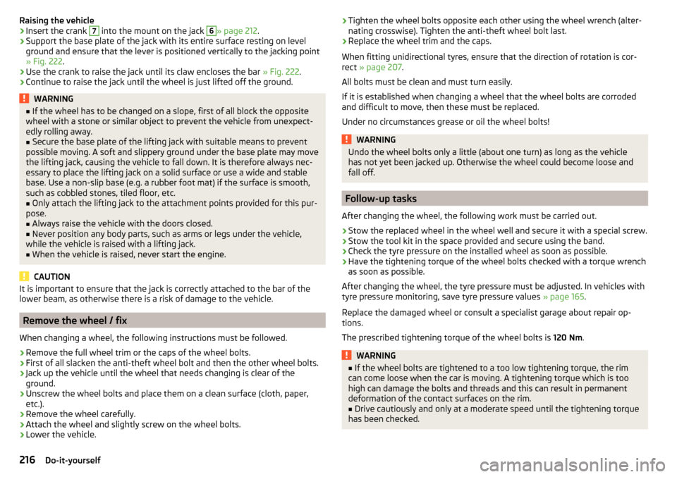
Raising the vehicle›Insert the crank 7 into the mount on the jack 6» page 212.›
Support the base plate of the jack with its entire surface resting on level
ground and ensure that the lever is positioned vertically to the jacking point
» Fig. 222 .
›
Use the crank to raise the jack until its claw encloses the bar » Fig. 222.
›
Continue to raise the jack until the wheel is just lifted off the ground.
WARNING■
If the wheel has to be changed on a slope, first of all block the opposite
wheel with a stone or similar object to prevent the vehicle from unexpect-
edly rolling away.■
Secure the base plate of the lifting jack with suitable means to prevent
possible moving. A soft and slippery ground under the base plate may move
the lifting jack, causing the vehicle to fall down. It is therefore always nec-
essary to place the lifting jack on a solid surface or use a wide and stable
base. Use a non-slip base (e.g. a rubber foot mat) if the surface is smooth,
such as cobbled stones, tiled floor, etc.
■
Only attach the lifting jack to the attachment points provided for this pur-
pose.
■
Always raise the vehicle with the doors closed.
■
Never position any body parts, such as arms or legs under the vehicle,
while the vehicle is raised with a lifting jack.
■
When the vehicle is raised, never start the engine.
CAUTION
It is important to ensure that the jack is correctly attached to the bar of the
lower beam, as otherwise there is a risk of damage to the vehicle.
Remove the wheel / fix
When changing a wheel, the following instructions must be followed.
›
Remove the full wheel trim or the caps of the wheel bolts.
›
First of all slacken the anti-theft wheel bolt and then the other wheel bolts.
›
Jack up the vehicle until the wheel that needs changing is clear of the
ground.
›
Unscrew the wheel bolts and place them on a clean surface (cloth, paper,
etc.).
›
Remove the wheel carefully.
›
Attach the wheel and slightly screw on the wheel bolts.
›
Lower the vehicle.
› Tighten the wheel bolts opposite each other using the wheel wrench (alter-
nating crosswise). Tighten the anti-theft wheel bolt last.›
Replace the wheel trim and the caps.
When fitting unidirectional tyres, ensure that the direction of rotation is cor-
rect » page 207 .
All bolts must be clean and must turn easily.
If it is established when changing a wheel that the wheel bolts are corroded and difficult to move, then these must be replaced.
Under no circumstances grease or oil the wheel bolts!
WARNINGUndo the wheel bolts only a little (about one turn) as long as the vehicle
has not yet been jacked up. Otherwise the wheel could become loose and
fall off.
Follow-up tasks
After changing the wheel, the following work must be carried out.
›
Stow the replaced wheel in the wheel well and secure it with a special screw.
›
Stow the tool kit in the space provided and secure using the band.
›
Check the tyre pressure on the installed wheel as soon as possible.
›
Have the tightening torque of the wheel bolts checked with a torque wrench
as soon as possible.
After changing the wheel, the tyre pressure must be adjusted. In vehicles with
tyre pressure monitoring, save tyre pressure values » page 165.
Replace the damaged wheel or consult a specialist garage about repair op-
tions.
The prescribed tightening torque of the wheel bolts is 120 Nm.
WARNING■
If the wheel bolts are tightened to a too low tightening torque, the rim
can come loose when the car is moving. A tightening torque which is too
high can damage the bolts and threads and this can result in permanent
deformation of the contact surfaces on the rim.■
Drive cautiously and only at a moderate speed until the tightening torque
has been checked.
216Do-it-yourself
Page 223 of 268
Vehicles with automatic transmission may be towed in with a tow bar or a tow
rope or with the front wheels raised. If the vehicle is raised at rear, the auto-
matic gearbox is damaged! If possible, the vehicle should be towed with the
engine running or at least with the ignition on.
Driver of the tow vehicle›
Engage the clutch gently when starting off or depress the accelerator partic-
ularly gently if the vehicle is fitted with an automatic gearbox.
›
Only then approach correctly when the rope is taut.
The maximum towing speed is 50 km/h.
Driver of the towed vehicle
›
Switch on the ignition so that the steering wheel is not locked and so that
the turn signal lights, windscreen wipers and windscreen washer system can
be used.
›
Take the vehicle out of gear or move the selector lever into position N if the
vehicle is fitted with an automatic gearbox.
Please note that the brake servo unit and power steering only operate if the
engine is running. If the engine is not running, significantly more physical force
is required to depress the brake pedal and steer the vehicle.
If using a tow rope, ensure that it is always kept taught.
General information for the towing process
Both drivers should be familiar with the problems which might possibly occur while a vehicle is being towed. Unskilled drivers should not attempt to tow in
another vehicle or to be towed in.
The vehicle must be transported on a special breakdown vehicle or trailer if it
is not possible to tow in the vehicle in the way described or if the towing dis-
tance is greater than 50 km.
If the gearbox no longer contains any oil, your vehicle must only be towed with
the front axle raised clear of the ground or on a breakdown vehicle or trailer.
To protect both vehicles when tow-starting or towing, the tow rope should be
elastic. Thus one should only use plastic fibre rope or a rope made out of a
similarly elastic material.
Attach the tow rope or the tow bar to the towing eyes » page 221 or
» page 222 to the detachable ball head of the towing equipment » page 167 .
WARNING■
When towing, exercise increased caution.■Spiral tow ropes must not be used for towing » Fig. 226- , the towing
eye may unscrew out of the vehicle - risk of accident.■
The tow rope should not be twisted - risk of accident.
CAUTION
■ Do not start engine by towing - there is a risk of damaging the engine parts.
The battery from another vehicle can be used as a jump-start aid » page 219,
Jump-starting .■
There is always a risk of excessive stresses and damage resulting at the
points to which you attach the tow rope or tow bar when you attempt to tow a
vehicle which is not standing on a paved road.
Note
We recommend using a tow rope from ŠKODA Original Accessories available
from a ŠKODA Partner.
Front towing eye
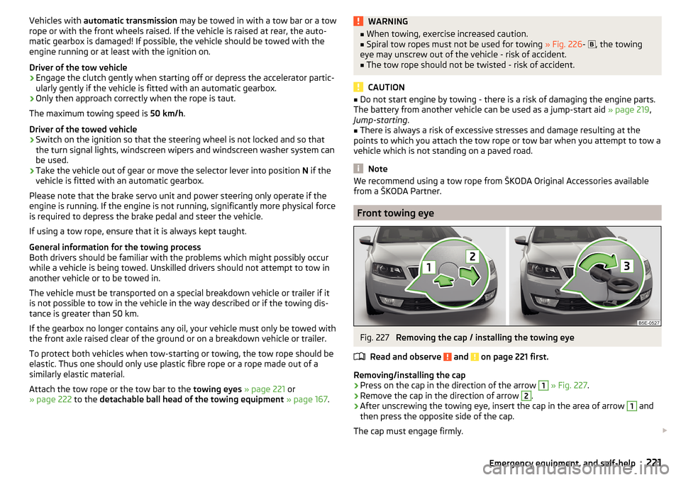
Fig. 227
Removing the cap / installing the towing eye
Read and observe
and on page 221 first.
Removing/installing the cap
›
Press on the cap in the direction of the arrow
1
» Fig. 227 .
›
Remove the cap in the direction of arrow
2
.
›
After unscrewing the towing eye, insert the cap in the area of arrow
1
and
then press the opposite side of the cap.
The cap must engage firmly.
221Emergency equipment, and self-help
Page 231 of 268
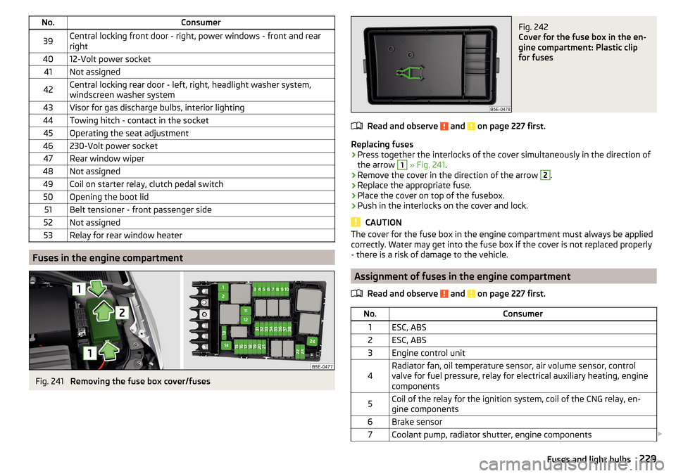
No.Consumer39Central locking front door - right, power windows - front and rear
right4012-Volt power socket41Not assigned42Central locking rear door - left, right, headlight washer system,
windscreen washer system43Visor for gas discharge bulbs, interior lighting44Towing hitch - contact in the socket45Operating the seat adjustment46230-Volt power socket47Rear window wiper48Not assigned49Coil on starter relay, clutch pedal switch50Opening the boot lid51Belt tensioner - front passenger side52Not assigned53Relay for rear window heater
Fuses in the engine compartment
Fig. 241
Removing the fuse box cover/fuses
Fig. 242
Cover for the fuse box in the en-
gine compartment: Plastic clip
for fuses
Read and observe and on page 227 first.
Replacing fuses
›
Press together the interlocks of the cover simultaneously in the direction of
the arrow
1
» Fig. 241 .
›
Remove the cover in the direction of the arrow
2
.
›
Replace the appropriate fuse.
›
Place the cover on top of the fusebox.
›
Push in the interlocks on the cover and lock.
CAUTION
The cover for the fuse box in the engine compartment must always be applied
correctly. Water may get into the fuse box if the cover is not replaced properly
- there is a risk of damage to the vehicle.
Assignment of fuses in the engine compartment
Read and observe
and on page 227 first.
No.Consumer1ESC, ABS2ESC, ABS3Engine control unit4Radiator fan, oil temperature sensor, air volume sensor, control
valve for fuel pressure, relay for electrical auxiliary heating, engine
components5Coil of the relay for the ignition system, coil of the CNG relay, en-
gine components6Brake sensor7Coolant pump, radiator shutter, engine components 229Fuses and light bulbs
Page 232 of 268
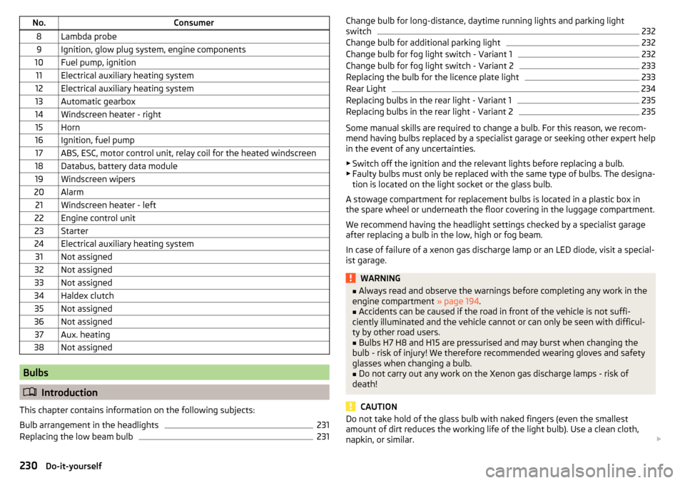
No.Consumer8Lambda probe9Ignition, glow plug system, engine components10Fuel pump, ignition11Electrical auxiliary heating system12Electrical auxiliary heating system13Automatic gearbox14Windscreen heater - right15Horn16Ignition, fuel pump17ABS, ESC, motor control unit, relay coil for the heated windscreen18Databus, battery data module19Windscreen wipers20Alarm21Windscreen heater - left22Engine control unit23Starter24Electrical auxiliary heating system31Not assigned32Not assigned33Not assigned34Haldex clutch35Not assigned36Not assigned37Aux. heating38Not assigned
Bulbs
Introduction
This chapter contains information on the following subjects:
Bulb arrangement in the headlights
231
Replacing the low beam bulb
231Change bulb for long-distance, daytime running lights and parking light
switch232
Change bulb for additional parking light
232
Change bulb for fog light switch - Variant 1
232
Change bulb for fog light switch - Variant 2
233
Replacing the bulb for the licence plate light
233
Rear Light
234
Replacing bulbs in the rear light - Variant 1
235
Replacing bulbs in the rear light - Variant 2
235
Some manual skills are required to change a bulb. For this reason, we recom-
mend having bulbs replaced by a specialist garage or seeking other expert help
in the event of any uncertainties.
▶ Switch off the ignition and the relevant lights before replacing a bulb.
▶ Faulty bulbs must only be replaced with the same type of bulbs. The designa-
tion is located on the light socket or the glass bulb.
A stowage compartment for replacement bulbs is located in a plastic box in
the spare wheel or underneath the floor covering in the luggage compartment.
We recommend having the headlight settings checked by a specialist garage
after replacing a bulb in the low, high or fog beam.
In case of failure of a xenon gas discharge lamp or an LED diode, visit a special- ist garage.
WARNING■ Always read and observe the warnings before completing any work in the
engine compartment » page 194.■
Accidents can be caused if the road in front of the vehicle is not suffi-
ciently illuminated and the vehicle cannot or can only be seen with difficul-
ty by other road users.
■
Bulbs H7 H8 and H15 are pressurised and may burst when changing the
bulb - risk of injury! We therefore recommended wearing gloves and safety
glasses when changing a bulb.
■
Do not carry out any work on the Xenon gas discharge lamps - risk of
death!
CAUTION
Do not take hold of the glass bulb with naked fingers (even the smallest
amount of dirt reduces the working life of the light bulb). Use a clean cloth,
napkin, or similar. 230Do-it-yourself
Page 252 of 268
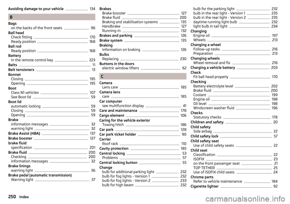
Avoiding damage to your vehicle134
B
Bags on the backs of the front seats
96
Ball head Check fitting
170
Ready position168
Ball rod Ready position
168
Battery In the remote control key
223
Belts11
Belt tensioners13
Bonnet Closing
195
Opening195
Boot Class N1 vehicles
107
See Boot lid59
Boot lid automatic locking
59
Closing59
Opening59
Brake information messages
32
warning light32
Brake Assist (HBA)137
Brake booster127
brake fluid specification
201
Brake fluid200
Checking200
information messages32
Brake linings warning light
36
Brake pedal (automatic transmission) Warning light
37
Brakes Brake booster127
Brake fluid200
Braking and stabilisation systems135
Handbrake127
Running-in132
Brakes and parking126
Brake system135
Braking Information on braking
126
Bulbs Replacing
230
Buttons in the doors electric window lifters
62
C
Camera Lens care
185
Camera lens care
185
Car computer see multifunction display
41
Care and maintenance178
Cargo element106
Caring for the vehicle exterior Towing hitch
186
Car park128
Car park ticket holder90
Carrier Roof rack
110
Cavity protection185
Central locking53
Problems57
Central locking button55
Change bulb for additional parking light
232
bulb for fog lights - Version 1232
bulb for fog lights - Version 2233
bulb for high beam232
bulb for the parking light232
bulb in the rear light - Version 1235
bulb in the rear light - Version 2235
daytime running light bulb232
light bulb in tail light234
Changing Engine oil
197
Wheels213
Changing a wheel Follow-up tasks
216
Preparation213
Changing wheels Wheel removal and fix
216
Charging a vehicle battery203
Check Fit ball head properly
170
Checking Battery electrolyte level
202
Brake fluid200
Coolant199
Engine oil198
Oil level198
Windscreen washer fluid196
Checks Statutory checks
178
Children and safety20
Child safety Side airbag
22
Child safety lock57
Child safety seat Use of child safety seats
22
Child seat Classification
22
ISOFIX23
on the front passenger seat21
TOP TETHER25
Use of ISOFIX child seats24
Chrome parts Refer to vehicle maintenance
184
Cigarette lighter92
250Index
Page 254 of 268
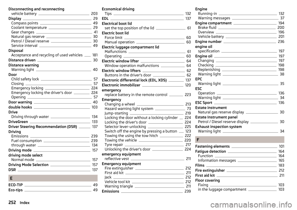
Disconnecting and reconnectingvehicle battery203
Display29
Compass points49
Coolant temperature29
Gear changes41
Natural gas reserve30
Petrol / Diesel reserve30
Service interval49
Disposal Acceptance and recycling of used vehicles
181
Distance driven30
Distance warning Warning light
40
Door Child safety lock
57
Closing57
Emergency locking224
Emergency locking the driver's door224
Opening57
Door warning40
double hooks103
Drive Driving through water
134
DriveGreen133
Driver Steering Recommendation (DSR)137
Driving Emissions
239
Fuel consumption239
through water134
Driving mode157
driving mode select Normal mode
157
Driving Mode Selection157
DSR137
E
ECO-TIP
49
Eco-tips49
Economical driving Tips132
EDL137
Electrical boot lid set the top position of the lid
61
Electric boot lid Force limit
60
Manual operation60
Electric luggage compartment lid Malfunctions
61
Operating60
Electric window lifter64
Window operation malfunctions64
Electric window lifters62
Buttons in the driver's door62
Electronic differential lock (EDL, XDS)137
Electronic immobilizer120
emergency replace battery in the remote control
223
Emergency Changing a wheel
213
Hazard warning light system73
Jump-starting219
Locking the door without a locking cylinder224
Locking the driver's door224
Selector lever-unlocking225
Switch off the engine by pressing a button123
Towing the using the tow hitch222
Towing the vehicle220
Tyre repair217
Unlocking the driver's door224
emergency equipment reflective vest
211
Emergency equipment Fire extinguisher
212
First aid kit211
Jack212
Vehicle tool kit212
Warning triangle211
Emissions239
Engine Running-in132
Warning messages37
Engine compartment194
Brake fluid200
Overview196
Vehicle battery201
Engine number236
engine oil specification
197
Engine oil197
Changing197
Checking198
Replenishing198
Warning light38
EPC Warning light
35
ESC Operation
136
Warning light34
ESC Sport136
Estate instrument Natural gas reserve display
30
Estate Instrument panel Petrol / Diesel reserve display
30
Exhaust inspection system Warning light
34
F
Fastening elements
101
Fatigue detection164
Function164
Information messages165
Films183
Fire extinguisher212
First aid kit211
Floor covering Fixing
103
in the luggage compartment103
252Index
Page 257 of 268
Luggage compartment lid59
Luggage net104
Luggage storage Multi-function pocket
107
M
Main beam
69
Warning light37
Maintenance see vehicle care
183
Manual air conditioning Air distribution control
115
Controls113
Manual gear changing see gear changing
128
Manually adjusting seats
82
Manually adjusting seats82
MAXI DOT display44
Lap timer48
Main menu45
Menu item assist systems48
Menu item Audio47
Menu item navigation46
Menu item telephone47
Operation45, 46
Stop watch48
MAXI DOT see MAXI DOT display
44
Maximum permissible weights
236
MCB138
Mechanical window lifter open and close
62
Mechanical window lifters61
Media AUX
99
see Infotainment4
USB99
Memory44
Memory Function for the seat84
Mirror Exterior mirrors
80
Interior mirror79
Make-up76
MODE button see driving mode selection
157
Modifications178
Modifications and technical alterations Airbags
180
Service179
Spoiler180
Multi-function display operation
42
Multi-function pocket107
Multi collision brake (MCB)138
Multifunction display Functions
41
Information42
Memory44
Multifunction steering wheel Operation
46
Multimedia AUX
99
USB99
Multimedia holder94
Handling99
N
N1
107
Nameplate236
Natural gas operation Warning light
37
Navigation see Infotainment
4
Net partition109
behind the front seats109
behind the rarer seats109
Removing and refitting the housing110
Nets102
NGVs see CNG
193
Notes for driving with a repaired tyre219
Notes on using wheels205
O
OFF ROAD
138
ABS140
EDS140
ESC140
hill descent assistant139
operation139
TCS140
OFF ROAD mode warning light
40
Oil See Engine oil
198
Warning messages38
Oil pressure Warning messages
38
On-board computer see multifunction display
41
Operating weight237
Operation in winter Diesel fuel
191
Vehicle battery202
Original accessories179
Overview Engine compartment
196
Warning lights31
255Index