stop start SKODA OCTAVIA 2015 3.G / (5E) Owner's Guide
[x] Cancel search | Manufacturer: SKODA, Model Year: 2015, Model line: OCTAVIA, Model: SKODA OCTAVIA 2015 3.G / (5E)Pages: 268, PDF Size: 37.54 MB
Page 158 of 268
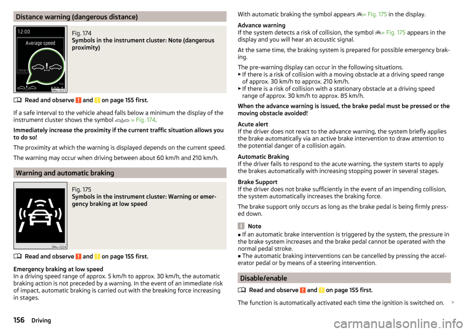
Distance warning (dangerous distance)Fig. 174
Symbols in the instrument cluster: Note (dangerous
proximity)
Read and observe and on page 155 first.
If a safe interval to the vehicle ahead falls below a minimum the display of the
instrument cluster shows the symbol
» Fig. 174 .
Immediately increase the proximity if the current traffic situation allows you to do so!
The proximity at which the warning is displayed depends on the current speed.
The warning may occur when driving between about 60 km/h and 210 km/h.
Warning and automatic braking
Fig. 175
Symbols in the instrument cluster: Warning or emer-
gency braking at low speed
Read and observe and on page 155 first.
Emergency braking at low speed
In a driving speed range of approx. 5 km/h to approx. 30 km/h, the automatic braking action is not preceded by a warning. In the event of an immediate risk
of impact, automatic braking is carried out with the breaking force increasing
in stages.
With automatic braking the symbol appears » Fig. 175 in the display.
Advance warning
If the system detects a risk of collision, the symbol
» Fig. 175 appears in the
display and you will hear an acoustic signal.
At the same time, the braking system is prepared for possible emergency brak-
ing.
The pre-warning display can occur in the following situations.
▶ If there is a risk of collision with a moving obstacle at a driving speed range
of approx. 30 km/h to approx. 210 km/h.
▶ If there is a risk of collision with a stationary obstacle at a driving speed
range of approx. 30 km/h to approx. 85 km/h.
When the advance warning is issued, the brake pedal must be pressed or the
moving obstacle avoided!
Acute alert
If the driver does not react to the advance warning, the system briefly applies
the brake automatically via an active brake intervention to draw attention to
the potential danger of a collision again.
Automatic Braking
If the driver fails to respond to the acute warning, the system starts to apply
the brakes automatically with increasing stopping power in several stages.
Brake Support
If the driver does not brake sufficiently in the event of an impending collision,
the system automatically increases the braking force.
The brake support only occurs as long as the brake pedal is being firmly press-
ed down.
Note
■ If an automatic brake intervention is triggered by the system, the pressure in
the brake system increases and the brake pedal cannot be operated with the
normal pedal stroke.■
The automatic braking interventions can be cancelled by pressing the accel-
erator pedal or by means of a steering intervention.
Disable/enable
Read and observe
and on page 155 first.
The function is automatically activated each time the ignition is switched on.
156Driving
Page 159 of 268
The system should only be disabled in exceptional cases » .
The system can be activated or deactivated in one of two ways. ▶ In the instrument cluster display » page 48, Menu itemAssist systems
.
▶ Infotainment » Owner´s Manual Infotainment , chapter CAR - vehicle set-
tings .
The following functions can be activated or deactivated separately in infotain-
ment. ▶ Distance warning
▶ Advance warning
f the distance-warning function was deactivated before switching off the igni-
tion, it remains deactivated after switching on the ignition.
WARNINGIn the following situations, Front Assist should be switched off for safety
reasons.■
When the vehicle is being towed away.
■
When the vehicle is on a rolling test bench.
■
If an unfounded warning was issued or a system action carried out.
■
When on a truck, car ferry or similar.
Information messages
Read and observe
and on page 155 first.
The information messages are shown in the instrument cluster display.
Front Assist: no sensor view.
The sensor is soiled or covered.
Stop the vehicle, switch off the engine and clean the sensor or remove the ob-
stacle causing the lack of visibility » page 135, Radar sensor .
If after engine start the message persists, then the help of a professional or-
ganisation is required.
Front Assist not available.
The system is not available for an unknown reason.
Stop the vehicle, switch off the engine and then start it again.
If after engine start the message persists, then the help of a professional or- ganisation is required.
Selection of the driving mode (Driving Mode Selection)
Introduction
This chapter contains information on the following subjects:
Normal157Sport
mode
157Eco
mode
158Individual
mode
158Off-road
mode
158
Mode selection and Infotainment display
159Individual
mode settings
159
By selecting the driving mode, the driving behaviour can be adapted to the de-
sired mode of operation.
The following modes of operation are available
Normal
,
Sport
,
Eco
,
Individual
and
Off-road
.
The mode
Off-road
is only available on the vehicles Octavia SCOUT.
WARNINGThe general information relating to the use of assistance systems must be
observed » page 135, in section Introduction .
Normal
Read and observe on page 157 first.
This mode is suitable for a conventional driving.
Sport
mode
Read and observe
on page 157 first.
This mode is suitable for a sporty driving.
Selecting this mode primarily affects the function of the following systems.
Steering
The power steering is reduced slightly, i.e., the driver needs to exert more
force for steering .
157Assist systems
Page 160 of 268
Engine / drive
The vehicle acceleration is more dynamic than in Normal
mode.
Front axle differential lock
The driving force distribution between the front wheels is adapted to the spor-
ty driving style.
Adaptive Cruise Control (ACC)
The acceleration is quicker than in
Normal
mode with distance control
» page 150 .
Xenon headlight
The headlamps adapt to the driving style more dynamically than in mode
Nor-mal
» page 70 .
ProActive passenger protection
The first level of protection is deactivated » page 160.
Engine noise
The engine noise is noticeable in the interior more intensely than in
Normal
mode.
Eco
mode
Read and observe
on page 157 first.
This mode is suitable for a relaxed style of driving and helps to save fuel.
Selecting this mode primarily affects the function of the following systems.
Engine / drive
Vehicle acceleration is more relaxed than in
Normal
mode.
The recommended gear is controlled such to achieve the lowest possible fuel
consumption » page 41.
When the START-STOP system was deactivated manually » page 124, it is au-
tomatically activated.
The automatic gearbox is set automatically to mode E » page 129 .
Adaptive Cruise Control (ACC)
Acceleration occurs more relaxed than in
Normal
» page 150 mode with distance
control.
Xenon headlight
The system is in economic mode » page 70. The headlamps are in basic setting
and do not adapt to the direction of travel.
Air conditioning (Climatronic)
The air conditioning is controlled so as to save energy. For this reason, for ex-
ample, it may take longer to reach the desired interior temperature in modeNormal
.
Note
■ The mode Eco is not available when towing a trailer or when another acces-
sory is connected to the trailer socket. If the vehicle is in drive mode Eco
and a
trailer is hitched up or another accessory is connected, the vehicle is automati-
cally set to the driving mode
Normal
.
■
The maximum vehicle acceleration (kick down function) is possible also in
driving mode
Eco
.
Individual
mode
Read and observe
on page 157 first.
In the mode
Individual
each system can be set independently » page 159,
Individ-ual
mode settings .
Off-road
mode
Read and observe
on page 157 first.
The mode
Off-road
is suitable for driving outside paved roads.
Further information » page 138, OFF ROAD-mode .
Note
The mode Off-road is deactivated after switching off and switching on the igni-
tion and the mode Normal
is set automatically.158Driving
Page 194 of 268
Preheating fuel
The vehicle is fitted with a fuel filter preheating system. This secures opera-
tion of a vehicle using diesel fuel down to an environmental temperature of
-24 °C.
Diesel fuel additives
The diesel fuel in accordance with the prescribed standards meets all the con-
ditions for a smooth running engine. We therefore recommend that no diesel
fuel additives are used. This can result in considerable damage to parts of the
engine or the exhaust system.
CAUTION
■ Just filling the tank once with diesel fuel that does not comply with the
standard, can cause severe damage to parts of the engine, the fuel and ex-
haust system.■
If a different fuel other than diesel fuel, which complies to the above men-
tioned standards (e.g. petrol) is used, do not start the engine or switch on the
ignition! Extensive damage to engine parts can occur.
■
Water which has collected in the fuel filter can cause engine faults.
CAUTION
■ The vehicle cannot be operated with bio fuel RME, therefore this fuel must
not be filled in the tank and used for driving the vehicle. The use of biofuel
RME can cause considerable damage to parts of the engine or fuel system.■
Do not mix any fuel additives, so-called “flow improvers” (petrol and similar
agents) into the diesel. This can result in considerable damage to parts of the
engine or the exhaust system.
Refuelling with CNG (compressed natural gas)
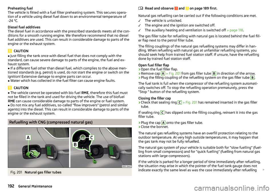
Fig. 201
Natural gas filler tubes
Read and observe and on page 189 first.
Natural gas refuelling can be carried out if the following conditions are met.
The vehicle is unlocked.
The engine and the ignition are switched off.
The auxiliary heating and ventilation is switched off » page 118.
The gas filler tube for refuelling with natural gas is located behind the fuel fill-
er flap next to the petrol filler tube.
The filling couplings of the natural gas refuelling systems may differ in han-
dling. When refuelling with natural gas at unfamiliar refuelling systems, you
should seek help from trained fuel station staff. If unsure, have the refuelling
done by trained fuel station staff.
Open fuel filler flap
›
Open the fuel filler flap.
›
Remove cap
A
» Fig. 201 from gas filler tube
B
in direction of the arrow.
›
Plug the filling coupling of the refuelling system on the gas filler tube
B
.
The fuel tank is full when the compressor of the refuelling system automati-
cally switches off. To stop the refuelling operation prematurely, press the
“Stop ” button of the refuelling system.
Closing the filler cap
›
Check that sealing ring
C
» Fig. 201 has remained inserted in the gas filler
tube.
If sealing ring
C
has slipped onto the filling coupling, reinsert it into the gas
filler tube.
›
Plug the cap
A
onto the gas filler tube.
›
Close the bonnet.
The natural gas refuelling systems have an overfill protection relating to the
outdoor temperature. At very high outside temperatures, it may happen that
the gas tank may not be fully refuelled.
The natural gas system of your vehicle is suitable both for “slow fuelling” (fuel-
ling from small compressors) and for “quick fuelling” (fuelling from natural gas
stations with large compressors).
If the vehicle is parked for a longer period of time immediately after refuelling,
the situation may arise in which the pointer of the fuel tank gauge does not
indicate exactly the same level as was the case immediately after refuelling
192General Maintenance
Page 195 of 268
when the engine is restarted. This is not due to any system leakages but a
drop in pressure in the natural gas fuel tank due to technical reasons after a
cooling phase directly after refuelling.
The maximum lifetime of the gas tank is 20 years.
The capacity of the natural gas fuel tank is approximately 15 kg.
The capacity of the gasoline fuel tank is about 50 litres, of which about 6
lighters are in reserve.WARNING■
When refuelling, never get into the vehicle. If you have to get into your
vehicle in exceptional cases, touch a metal surface before you touch the
filling coupling again. This will avoid electrostatic discharges, which may
generate sparks. Sparks can cause a fire during refuelling.■
Natural gas is highly explosive and highly flammable.
Note
During the filling process sounds are heard which are harmless. If you are un-
sure which service station staff to use, ask the petrol station staff.
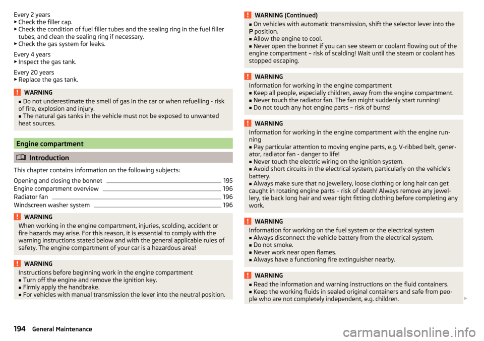
CNG
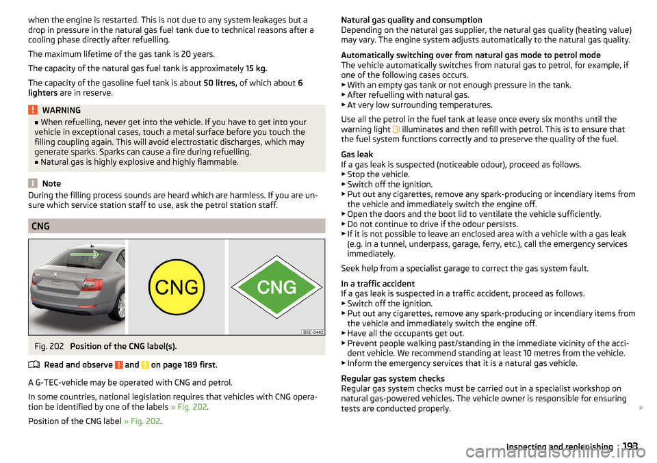
Fig. 202
Position of the CNG label(s).
Read and observe
and on page 189 first.
A G-TEC-vehicle may be operated with CNG and petrol.
In some countries, national legislation requires that vehicles with CNG opera-
tion be identified by one of the labels » Fig. 202.
Position of the CNG label » Fig. 202.
Natural gas quality and consumption
Depending on the natural gas supplier, the natural gas quality (heating value) may vary. The engine system adjusts automatically to the natural gas quality.
Automatically switching over from natural gas mode to petrol mode
The vehicle automatically switches from natural gas to petrol, for example, if
one of the following cases occurs. ▶ With an empty gas tank or not enough pressure in the tank.
▶ After refuelling with natural gas.
▶ At very low surrounding temperatures.
Use all the petrol in the fuel tank at lease once every six months until the
warning light
illuminates and then refill with petrol. This is to ensure that
the fuel system functions correctly and to preserve the quality of the fuel.
Gas leak
If a gas leak is suspected (noticeable odour), proceed as follows. ▶ Stop the vehicle.
▶ Switch off the ignition.
▶ Put out any cigarettes, remove any spark-producing or incendiary items from
the vehicle and immediately switch the engine off.
▶ Open the doors and the boot lid to ventilate the vehicle sufficiently.
▶ Do not continue to drive if the odour persists.
▶ If it is not possible to leave an enclosed area with a vehicle with a gas leak
(e.g. in a tunnel, underpass, garage, ferry, etc.), call the emergency services
immediately.
Seek help from a specialist garage to correct the gas system fault.
In a traffic accident
If a gas leak is suspected in a traffic accident, proceed as follows.
▶ Switch off the ignition.
▶ Put out any cigarettes, remove any spark-producing or incendiary items from
the vehicle and immediately switch the engine off.
▶ Have all the occupants get out.
▶ Prevent people walking past/standing in the immediate vicinity of the acci-
dent vehicle. We recommend standing at least 10 metres from the vehicle.
▶ Inform the emergency services that it is a natural gas vehicle.
Regular gas system checks
Regular gas system checks must be carried out in a specialist workshop on
natural gas-powered vehicles. The vehicle owner is responsible for ensuring
tests are conducted properly. 193Inspecting and replenishing
Page 196 of 268
Every 2 years
▶ Check the filler cap.
▶ Check the condition of fuel filler tubes and the sealing ring in the fuel filler
tubes, and clean the sealing ring if necessary.
▶ Check the gas system for leaks.
Every 4 years
▶ Inspect the gas tank.
Every 20 years ▶ Replace the gas tank.WARNING■ Do not underestimate the smell of gas in the car or when refuelling - risk
of fire, explosion and injury.■
The natural gas tanks in the vehicle must not be exposed to unwanted
heat sources.
Engine compartment
Introduction
This chapter contains information on the following subjects:
Opening and closing the bonnet
195
Engine compartment overview
196
Radiator fan
196
Windscreen washer system
196WARNINGWhen working in the engine compartment, injuries, scolding, accident or
fire hazards may arise. For this reason, it is essential to comply with the
warning instructions stated below and with the general applicable rules of
safety. The engine compartment of your car is a hazardous area!WARNINGInstructions before beginning work in the engine compartment■Turn off the engine and remove the ignition key.■
Firmly apply the handbrake.
■
For vehicles with manual transmission the lever into the neutral position.
WARNING (Continued)■ On vehicles with automatic transmission, shift the selector lever into the
P position.■
Allow the engine to cool.
■
Never open the bonnet if you can see steam or coolant flowing out of the
engine compartment – risk of scalding! Wait until the steam or coolant has
stopped escaping.
WARNINGInformation for working in the engine compartment■Keep all people, especially children, away from the engine compartment.■
Never touch the radiator fan. The fan might suddenly start running!
■
Do not touch any hot engine parts – risk of burns!
WARNINGInformation for working in the engine compartment with the engine run-
ning■
Pay particular attention to moving engine parts, e.g. V-ribbed belt, gener-
ator, radiator fan - danger to life!
■
Never touch the electric wiring on the ignition system.
■
Avoid short circuits in the electrical system, particularly on the vehicle's
battery.
■
Always make sure that no jewellery, loose clothing or long hair can get
caught in rotating engine parts – risk of death! Always remove any jewel-
lery, tie back long hair and wear tight fitting clothing before completing any
work.
WARNINGInformation for working on the fuel system or the electrical system■Always disconnect the vehicle battery from the electrical system.■
Do not smoke.
■
Never work near open flames.
■
Always have a functioning fire extinguisher nearby.
WARNING■ Read the information and warning instructions on the fluid containers.■Keep the working fluids in sealed original containers and safe from peo-
ple who are not completely independent, e.g. children. 194General Maintenance
Page 204 of 268
WARNING■The use of open flames and light should be avoided.■Smoking and radio triggering activities should be avoided.■
Never use a damaged vehicle battery – risk of explosion!
■
Never charge a frozen or thawed vehicle battery – risk of explosion and
caustic burns!
■
Replace a frozen vehicle battery.
■
Never jump-start vehicle batteries with an electrolyte level that is too low
– risk of explosion and caustic burns.
CAUTION
■ Improper handling of the vehicle battery may cause damage.■Ensure that battery acid does not come into contact with the bodywork – risk
of damage to the paintwork.■
If the vehicle has not been driven for more than 3 to 4 weeks, the battery will
discharge. Prevent the battery from discharging by disconnecting the battery's
negative terminal
or continuously charging the battery with a very low
charging current.
■
Do not place the battery in direct daylight in order to protect the vehicle bat-
tery housing from the effects of ultra-violet light.
■
If the vehicle is frequently used for making short trips, the vehicle battery
will not have time to charge up sufficiently and may discharge.
Note
■ We recommend having all work on the vehicle battery carried out by a spe-
cialist garage.■
You should replace batteries older than 5 years.
Opening the cover
Fig. 209
Polyester cover of vehicle bat-
tery
Read and observe and on page 201 first.
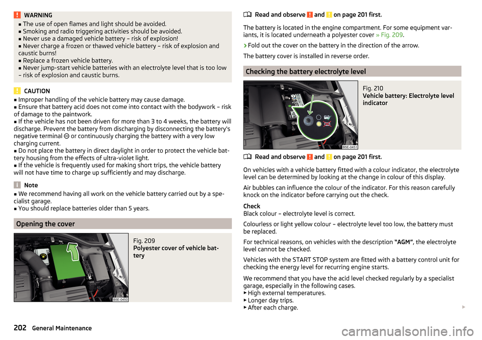
The battery is located in the engine compartment. For some equipment var- iants, it is located underneath a polyester cover » Fig. 209.
›
Fold out the cover on the battery in the direction of the arrow.
The battery cover is installed in reverse order.
Checking the battery electrolyte level
Fig. 210
Vehicle battery: Electrolyte level
indicator
Read and observe and on page 201 first.
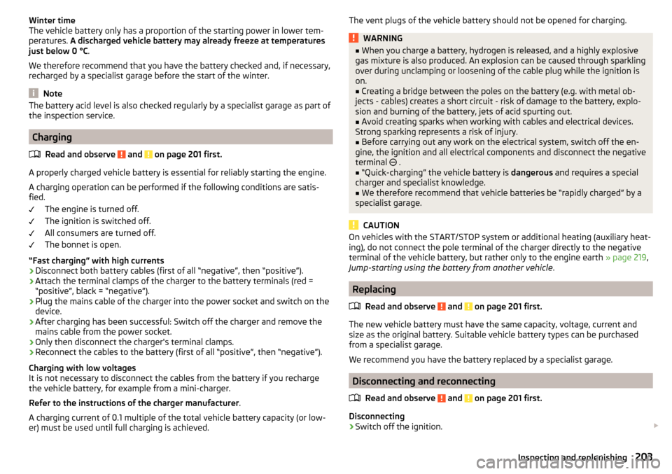
On vehicles with a vehicle battery fitted with a colour indicator, the electrolyte
level can be determined by looking at the change in colour of this display.
Air bubbles can influence the colour of the indicator. For this reason carefully
knock on the indicator before carrying out the check.
Check
Black colour – electrolyte level is correct.
Colourless or light yellow colour – electrolyte level too low, the battery must
be replaced.
For technical reasons, on vehicles with the description “AGM”, the electrolyte
level cannot be checked.
Vehicles with the START STOP system are fitted with a battery control unit for
checking the energy level for recurring engine starts.
We recommend that you have the acid level checked regularly by a specialist
garage, especially in the following cases. ▶ High external temperatures.
▶ Longer day trips.
▶ After each charge.
202General Maintenance
Page 205 of 268
Winter time
The vehicle battery only has a proportion of the starting power in lower tem-
peratures. A discharged vehicle battery may already freeze at temperatures
just below 0 °C .
We therefore recommend that you have the battery checked and, if necessary,
recharged by a specialist garage before the start of the winter.
Note
The battery acid level is also checked regularly by a specialist garage as part of
the inspection service.
Charging
Read and observe
and on page 201 first.
A properly charged vehicle battery is essential for reliably starting the engine.A charging operation can be performed if the following conditions are satis-
fied.
The engine is turned off.
The ignition is switched off.
All consumers are turned off.
The bonnet is open.
“Fast charging” with high currents
›
Disconnect both battery cables (first of all “negative”, then “positive”).
›
Attach the terminal clamps of the charger to the battery terminals (red =
“positive”, black = “negative”).
›
Plug the mains cable of the charger into the power socket and switch on the
device.
›
After charging has been successful: Switch off the charger and remove the
mains cable from the power socket.
›
Only then disconnect the charger's terminal clamps.
›
Reconnect the cables to the battery (first of all “positive”, then “negative”).
Charging with low voltages
It is not necessary to disconnect the cables from the battery if you recharge
the vehicle battery, for example from a mini-charger.
Refer to the instructions of the charger manufacturer .
A charging current of 0.1 multiple of the total vehicle battery capacity (or low-
er) must be used until full charging is achieved.
The vent plugs of the vehicle battery should not be opened for charging.WARNING■ When you charge a battery, hydrogen is released, and a highly explosive
gas mixture is also produced. An explosion can be caused through sparkling
over during unclamping or loosening of the cable plug while the ignition is
on.■
Creating a bridge between the poles on the battery (e.g. with metal ob-
jects - cables) creates a short circuit - risk of damage to the battery, explo-
sion and burning of the battery, jets of acid spurting out.
■
Avoid creating sparks when working with cables and electrical devices.
Strong sparking represents a risk of injury.
■
Before carrying out any work on the electrical system, switch off the en-
gine, the ignition and all electrical components and disconnect the negative
terminal
.
■
“Quick-charging” the vehicle battery is dangerous and requires a special
charger and specialist knowledge.
■
We therefore recommend that vehicle batteries be “rapidly charged” by a
specialist garage.
CAUTION
On vehicles with the START/STOP system or additional heating (auxiliary heat-
ing), do not connect the pole terminal of the charger directly to the negative
terminal of the vehicle battery, but rather only to the engine earth » page 219,
Jump-starting using the battery from another vehicle .
Replacing
Read and observe
and on page 201 first.
The new vehicle battery must have the same capacity, voltage, current and
size as the original battery. Suitable vehicle battery types can be purchased
from a specialist garage.
We recommend you have the battery replaced by a specialist garage.
Disconnecting and reconnecting
Read and observe
and on page 201 first.
Disconnecting
›
Switch off the ignition.
203Inspecting and replenishing
Page 222 of 268
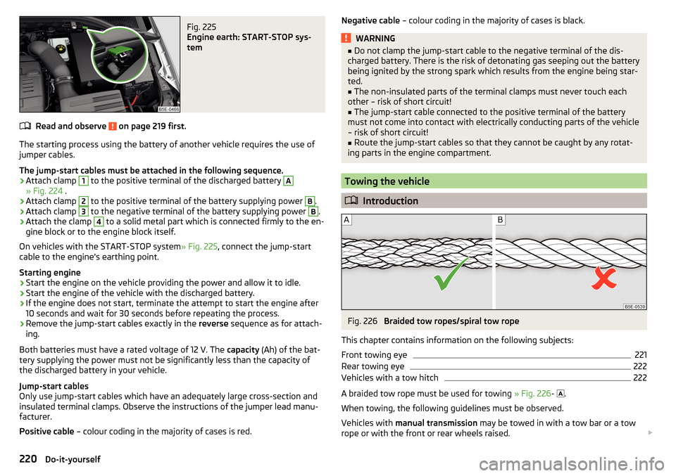
Fig. 225
Engine earth: START-STOP sys-
tem
Read and observe on page 219 first.
The starting process using the battery of another vehicle requires the use of
jumper cables.
The jump-start cables must be attached in the following sequence.
›
Attach clamp
1
to the positive terminal of the discharged battery
A
» Fig. 224 .
›
Attach clamp
2
to the positive terminal of the battery supplying power
B
.
›
Attach clamp
3
to the negative terminal of the battery supplying power
B
.
›
Attach the clamp
4
to a solid metal part which is connected firmly to the en-
gine block or to the engine block itself.
On vehicles with the START-STOP system » Fig. 225, connect the jump-start
cable to the engine's earthing point.
Starting engine
›
Start the engine on the vehicle providing the power and allow it to idle.
›
Start the engine of the vehicle with the discharged battery.
›
If the engine does not start, terminate the attempt to start the engine after
10 seconds and wait for 30 seconds before repeating the process.
›
Remove the jump-start cables exactly in the reverse sequence as for attach-
ing.
Both batteries must have a rated voltage of 12 V. The capacity (Ah) of the bat-
tery supplying the power must not be significantly less than the capacity of
the discharged battery in your vehicle.
Jump-start cables
Only use jump-start cables which have an adequately large cross-section and
insulated terminal clamps. Observe the instructions of the jumper lead manu-
facturer.
Positive cable – colour coding in the majority of cases is red.
Negative cable – colour coding in the majority of cases is black.WARNING■
Do not clamp the jump-start cable to the negative terminal of the dis-
charged battery. There is the risk of detonating gas seeping out the battery
being ignited by the strong spark which results from the engine being star-
ted.■
The non-insulated parts of the terminal clamps must never touch each
other – risk of short circuit!
■
The jump-start cable connected to the positive terminal of the battery
must not come into contact with electrically conducting parts of the vehicle
– risk of short circuit!
■
Route the jump-start cables so that they cannot be caught by any rotat-
ing parts in the engine compartment.
Towing the vehicle
Introduction
Fig. 226
Braided tow ropes/spiral tow rope
This chapter contains information on the following subjects:
Front towing eye
221
Rear towing eye
222
Vehicles with a tow hitch
222
A braided tow rope must be used for towing » Fig. 226-
.
When towing, the following guidelines must be observed.
Vehicles with manual transmission may be towed in with a tow bar or a tow
rope or with the front or rear wheels raised.
220Do-it-yourself
Page 224 of 268
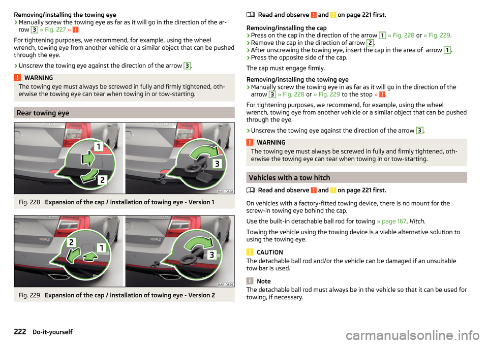
Removing/installing the towing eye›Manually screw the towing eye as far as it will go in the direction of the ar-
row 3
» Fig. 227 » .
For tightening purposes, we recommend, for example, using the wheel
wrench, towing eye from another vehicle or a similar object that can be pushed through the eye.
›
Unscrew the towing eye against the direction of the arrow
3
.
WARNINGThe towing eye must always be screwed in fully and firmly tightened, oth-
erwise the towing eye can tear when towing in or tow-starting.
Rear towing eye
Fig. 228
Expansion of the cap / installation of towing eye - Version 1
Fig. 229
Expansion of the cap / installation of towing eye - Version 2
Read and observe and on page 221 first.
Removing/installing the cap
›
Press on the cap in the direction of the arrow
1
» Fig. 228 or » Fig. 229 .
›
Remove the cap in the direction of arrow
2
.
›
After unscrewing the towing eye, insert the cap in the area of arrow
1
.
›
Press the opposite side of the cap.
The cap must engage firmly.
Removing/installing the towing eye
›
Manually screw the towing eye in as far as it will go in the direction of the
arrow
3
» Fig. 228 or » Fig. 229 to the stop » .
For tightening purposes, we recommend, for example, using the wheel
wrench, towing eye from another vehicle or a similar object that can be pushed through the eye.
›
Unscrew the towing eye against the direction of the arrow
3
.
WARNINGThe towing eye must always be screwed in fully and firmly tightened, oth-
erwise the towing eye can tear when towing in or tow-starting.
Vehicles with a tow hitch
Read and observe
and on page 221 first.
On vehicles with a factory-fitted towing device, there is no mount for the
screw-in towing eye behind the cap.
Use the built-in detachable ball rod for towing » page 167, Hitch .
Towing the vehicle using the towing device is a viable alternative solution to
using the towing eye.
CAUTION
The detachable ball rod and/or the vehicle can be damaged if an unsuitable
tow bar is used.
Note
The detachable ball rod must always be in the vehicle so that it can be used for
towing, if necessary.222Do-it-yourself