tow SKODA OCTAVIA 2015 3.G / (5E) Owner's Guide
[x] Cancel search | Manufacturer: SKODA, Model Year: 2015, Model line: OCTAVIA, Model: SKODA OCTAVIA 2015 3.G / (5E)Pages: 268, PDF Size: 37.54 MB
Page 160 of 268
Engine / drive
The vehicle acceleration is more dynamic than in Normal
mode.
Front axle differential lock
The driving force distribution between the front wheels is adapted to the spor-
ty driving style.
Adaptive Cruise Control (ACC)
The acceleration is quicker than in
Normal
mode with distance control
» page 150 .
Xenon headlight
The headlamps adapt to the driving style more dynamically than in mode
Nor-mal
» page 70 .
ProActive passenger protection
The first level of protection is deactivated » page 160.
Engine noise
The engine noise is noticeable in the interior more intensely than in
Normal
mode.
Eco
mode
Read and observe
on page 157 first.
This mode is suitable for a relaxed style of driving and helps to save fuel.
Selecting this mode primarily affects the function of the following systems.
Engine / drive
Vehicle acceleration is more relaxed than in
Normal
mode.
The recommended gear is controlled such to achieve the lowest possible fuel
consumption » page 41.
When the START-STOP system was deactivated manually » page 124, it is au-
tomatically activated.
The automatic gearbox is set automatically to mode E » page 129 .
Adaptive Cruise Control (ACC)
Acceleration occurs more relaxed than in
Normal
» page 150 mode with distance
control.
Xenon headlight
The system is in economic mode » page 70. The headlamps are in basic setting
and do not adapt to the direction of travel.
Air conditioning (Climatronic)
The air conditioning is controlled so as to save energy. For this reason, for ex-
ample, it may take longer to reach the desired interior temperature in modeNormal
.
Note
■ The mode Eco is not available when towing a trailer or when another acces-
sory is connected to the trailer socket. If the vehicle is in drive mode Eco
and a
trailer is hitched up or another accessory is connected, the vehicle is automati-
cally set to the driving mode
Normal
.
■
The maximum vehicle acceleration (kick down function) is possible also in
driving mode
Eco
.
Individual
mode
Read and observe
on page 157 first.
In the mode
Individual
each system can be set independently » page 159,
Individ-ual
mode settings .
Off-road
mode
Read and observe
on page 157 first.
The mode
Off-road
is suitable for driving outside paved roads.
Further information » page 138, OFF ROAD-mode .
Note
The mode Off-road is deactivated after switching off and switching on the igni-
tion and the mode Normal
is set automatically.158Driving
Page 165 of 268
WARNING■The general information relating to the use of assistance systems must
be observed » page 135, in section Introduction .■
Vertical traffic signs must always take precedence over the traffic signs
shown in the display. The driver is always responsible for correctly assess-
ing the traffic situation.
■
Traffic signs may not be recognised at all by the system, or may be recog-
nised incorrectly. As a result, the traffic signs may not be displayed at all, or
the wrong one may appear.
■
On the system side, only a traffic sign display is undertaken, neither a
warning when limit is exceeded or driving speed adjustment is undertaken!
■
Speed specifications on the displayed road signs refer to the country-spe-
cific speed units. For example, the display
on the display can therefore
refer to km/h or mph depending on the country.
Note
The system is only available in some countries.
Function
Fig. 181
Camera viewing range for traffic
sign recognition
Fig. 182
Display in the instrument cluster: Display examples
Read and observe
on page 163 first.
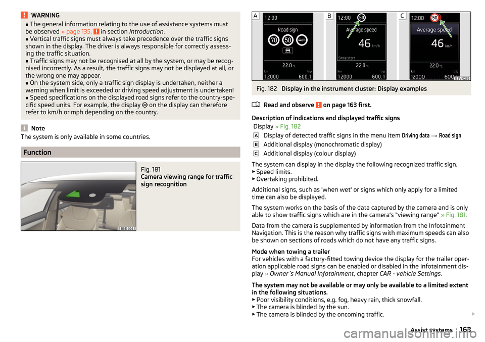
Description of indications and displayed traffic signs
Display » Fig. 182Display of detected traffic signs in the menu item Driving data → Road signAdditional display (monochromatic display)Additional display (colour display)
The system can display in the display the following recognized traffic sign.
▶ Speed limits.
▶ Overtaking prohibited.
Additional signs, such as 'when wet' or signs which only apply for a limited
time can also be displayed.
The system works on the basis of the data captured by the camera and is only
able to show traffic signs which are in the camera's “viewing range” » Fig. 181.
Data from the camera is supplemented by information from the Infotainment
Navigation. This is the reason why traffic signs with maximum speeds can also
be shown on sections of roads which do not have any traffic signs.
Mode when towing a trailer
For vehicles with a factory-fitted towing device the display for the trailer oper- ation applicable road signs can be enabled or disabled in the Infotainment dis-
play » Owner´s Manual Infotainment , chapter CAR - vehicle Settings .
The system may not be available or may only be available to a limited extent
in the following situations.
▶ Poor visibility conditions, e.g. fog, heavy rain, thick snowfall.
▶ The camera is blinded by the sun.
▶ The camera is blinded by the oncoming traffic.
163Assist systems
Page 169 of 268
Hitch and trailer
Hitch
Introduction
This chapter contains information on the following subjects:
Description
167
Adjusting the ready position
168
Correctly adjusted ready position
168
Assembling the bar ball – Step 1
169
Assembling the bar ball – Step 2
169
Check proper fitting
170
Removing the bar ball – Step 1
170
Removing the bar ball – Step 2
171
Mount accessories
171
The maximum trailer drawbar load is 75 kg.
For vehicles with all-wheel drive, the maximum trailer nose weight is 80 kg.
With G-TEC-vehicles, the maximum trailer drawbar load is 56 kg .
The draw bar load information on the type plate of the towing device is merely
a test value for the towing device. The vehicle-specific information is detailed
in the vehicle documents.
WARNING■ Before each time you make a journey when using the ball rod, check that
it is seated correctly and is secured in the mounting recess.■
Do not use the ball rod if it is not correctly inserted into the mounting re-
cess and secured.
■
Do not use the towing hitch if it is damaged or if there are parts missing.
■
Do not perform any modifications or changes to the towing device.
■
Keep the mounting recess of the towing device clean at all times. Such
dirt prevents the ball rod from being attached securely!
CAUTION
■ Take care when using the ball rod - there is a risk of paint damage to the
bumper.■
When the ball rod is removed always place the cover onto the mounting re-
cess - there is a danger of soiling the mounting recess.
Note■ Operation and maintenance of the tow hitch » page 186.■The towing vehicle by means of the detachable ball rod » page 222.■
If the towing device is removed completely, it must be replaced with the
original reinforcement of the rear bumper which is part of the mount for the
towing eye.
Description
Fig. 185
Support for the hitch equipment / ball bar / key (Version 1 and 2)
Read and observe
and on page 167 first.
The ball rod can be removed and is located in the spare wheel well or in a com-
partment for the spare wheel in the luggage compartment.
The hitch comes with two key versions. The handling of the hitch is identical
for the two key versions. The difference is only in the key version.
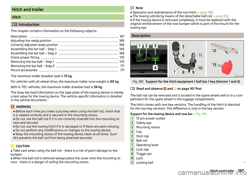
Support for the towing device and tow bar » Fig. 185
13-pin power socket
Safety eye
Mounting recess
Cap
Dust cap
Ball rod
Operating lever
Lock cap
Trigger pin
Lock
Locking ball
1234567891011167Hitch and trailer
Page 170 of 268

Key – Version 1
Key – Version 2
Note
If you lose the key, please get in touch with a specialist garage.
Adjusting the ready position
Fig. 186
Gear 1 Step: Key Version 1 / key Version 2
Fig. 187
Step 2: Both key versions
Read and observe and on page 167 first.
The ball rod must be set to the ready position prior to installation » page 168,
Correctly adjusted ready position .
If it is not in the ready position, then it must be set to the ready position as
follows.
Gear 1 Step - applies to the key version 1
›
Remove the cap from the lock
›
Insert key
A
into the lock so that the green marking is pointing upwards.
1213› Turn key A in the direction of arrow 1 so that the red marking is pointing
upwards » Fig. 186 .
Gear 1 Step - applies to the key version 2›
Remove the cap from the lock
›
Insert key
B
into the lock so that the eye of the key is pointing downwards.
›
Turn the key in the direction of arrow
B
2
so that the conclusions release
shows up » Fig. 186.
Gear 2 Step - applies to both key versions
›
Grip the tow bar below the protective cap.
›
Push release pin
C
in the direction of arrow
3
to the stop, and simultane-
ously push operating lever
D
in the direction of arrow
4
to the stop
» Fig. 187 .
Operating lever
D
remains locked in this position.
Correctly adjusted ready position
Fig. 188
Ready position: Key Version 1 / key Version 2 / position of the
lever and the release bolt with two key versions
Read and observe
and on page 167 first.
Correctly adjusted standby position » Fig. 188
Applies to key version 1 - the red marking on key
A
is pointing upwards.
Applies to key version 2 - the eye of the key
B
is pointing upwards.
Operating lever
C
is locked in the lower position.
The trigger pin
D
can be moved.
The ball bar is thus set ready for installation.
168Driving
Page 171 of 268
CAUTIONIn the ready position, the key cannot be removed nor turned into a different
position.
Assembling the bar ball – Step 1
Fig. 189
Insert ball rod / trigger bolt in the extended state
Read and observe
and on page 167 first.
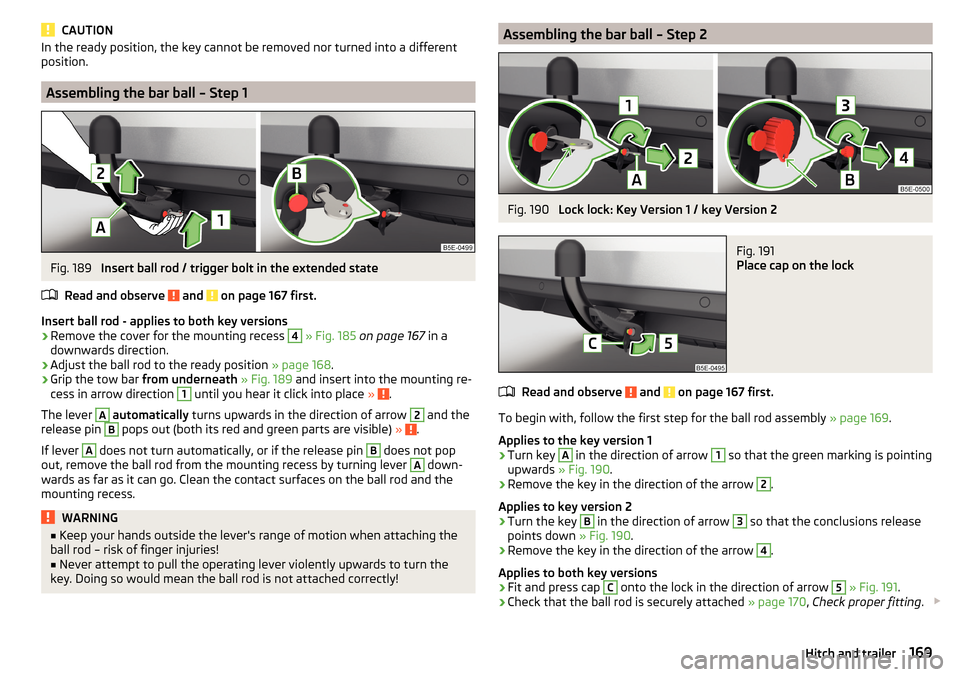
Insert ball rod - applies to both key versions
›
Remove the cover for the mounting recess
4
» Fig. 185 on page 167 in a
downwards direction.
›
Adjust the ball rod to the ready position » page 168.
›
Grip the tow bar from underneath » Fig. 189 and insert into the mounting re-
cess in arrow direction
1
until you hear it click into place » .
The lever
A
automatically turns upwards in the direction of arrow
2
and the
release pin
B
pops out (both its red and green parts are visible) » .
If lever
A
does not turn automatically, or if the release pin
B
does not pop
out, remove the ball rod from the mounting recess by turning lever
A
down-
wards as far as it can go. Clean the contact surfaces on the ball rod and the
mounting recess.
WARNING■ Keep your hands outside the lever's range of motion when attaching the
ball rod – risk of finger injuries!■
Never attempt to pull the operating lever violently upwards to turn the
key. Doing so would mean the ball rod is not attached correctly!
Assembling the bar ball – Step 2Fig. 190
Lock lock: Key Version 1 / key Version 2
Fig. 191
Place cap on the lock
Read and observe and on page 167 first.
To begin with, follow the first step for the ball rod assembly » page 169.
Applies to the key version 1
›
Turn key
A
in the direction of arrow
1
so that the green marking is pointing
upwards » Fig. 190 .
›
Remove the key in the direction of the arrow
2
.
Applies to key version 2
›
Turn the key
B
in the direction of arrow
3
so that the conclusions release
points down » Fig. 190.
›
Remove the key in the direction of the arrow
4
.
Applies to both key versions
›
Fit and press cap
C
onto the lock in the direction of arrow
5
» Fig. 191 .
›
Check that the ball rod is securely attached » page 170, Check proper fitting .
169Hitch and trailer
Page 172 of 268
CAUTIONAfter removing the key, always replace the cover on the lock – there is a risk of
the lock getting dirty.
Check proper fitting
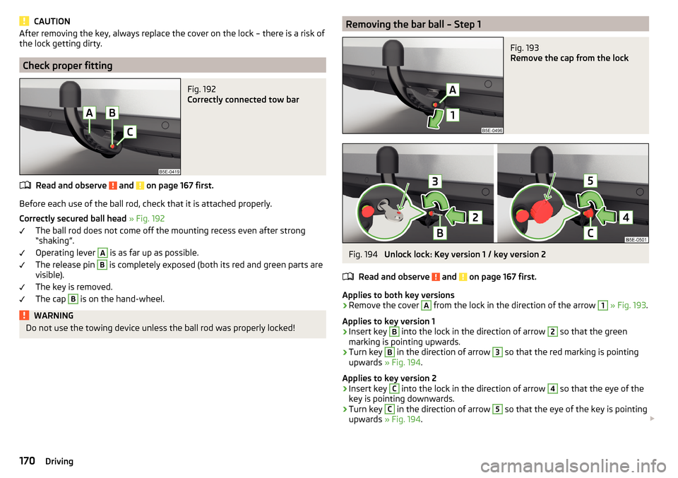
Fig. 192
Correctly connected tow bar
Read and observe and on page 167 first.
Before each use of the ball rod, check that it is attached properly.
Correctly secured ball head » Fig. 192
The ball rod does not come off the mounting recess even after strong
“shaking”.
Operating lever
A
is as far up as possible.
The release pin
B
is completely exposed (both its red and green parts are
visible).
The key is removed.
The cap
B
is on the hand-wheel.
WARNINGDo not use the towing device unless the ball rod was properly locked!Removing the bar ball – Step 1Fig. 193
Remove the cap from the lock
Fig. 194
Unlock lock: Key version 1 / key version 2
Read and observe
and on page 167 first.
Applies to both key versions
›
Remove the cover
A
from the lock in the direction of the arrow
1
» Fig. 193 .
Applies to key version 1
›
Insert key
B
into the lock in the direction of arrow
2
so that the green
marking is pointing upwards.
›
Turn key
B
in the direction of arrow
3
so that the red marking is pointing
upwards » Fig. 194 .
Applies to key version 2
›
Insert key
C
into the lock in the direction of arrow
4
so that the eye of the
key is pointing downwards.
›
Turn key
C
in the direction of arrow
5
so that the eye of the key is pointing
upwards » Fig. 194 .
170Driving
Page 173 of 268
WARNINGNever remove the tow bar while the trailer is still coupled.
Note
We recommend putting the protective cover onto the ball head before remov-
ing the tow bar.
Removing the bar ball – Step 2
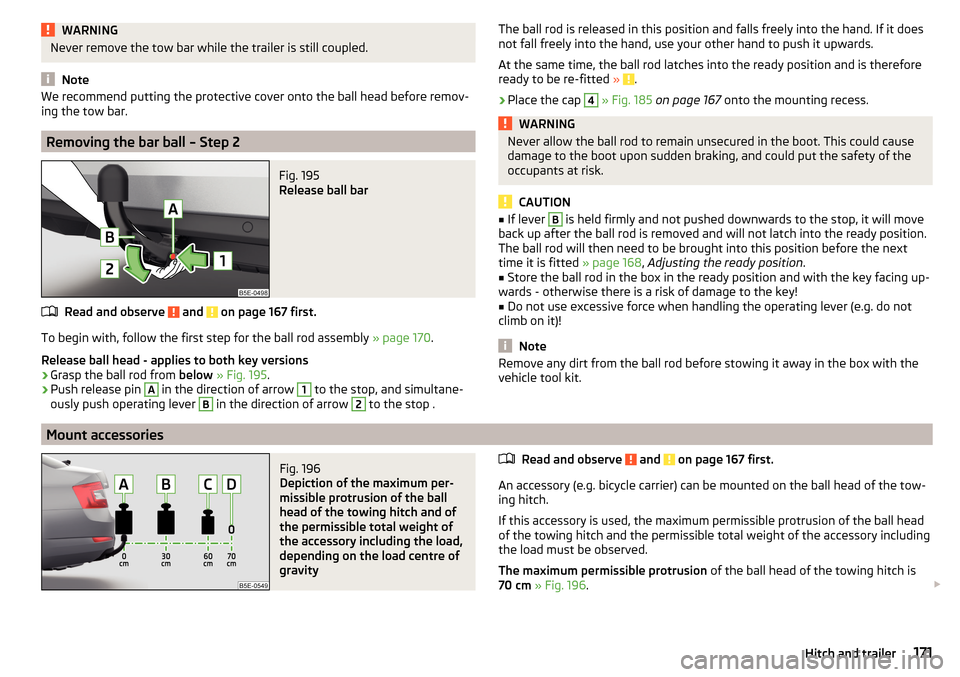
Fig. 195
Release ball bar
Read and observe and on page 167 first.
To begin with, follow the first step for the ball rod assembly » page 170.
Release ball head - applies to both key versions
›
Grasp the ball rod from below » Fig. 195 .
›
Push release pin
A
in the direction of arrow
1
to the stop, and simultane-
ously push operating lever
B
in the direction of arrow
2
to the stop .
The ball rod is released in this position and falls freely into the hand. If it does
not fall freely into the hand, use your other hand to push it upwards.
At the same time, the ball rod latches into the ready position and is therefore
ready to be re-fitted »
.
›
Place the cap
4
» Fig. 185 on page 167 onto the mounting recess.
WARNINGNever allow the ball rod to remain unsecured in the boot. This could cause
damage to the boot upon sudden braking, and could put the safety of the
occupants at risk.
CAUTION
■ If lever B is held firmly and not pushed downwards to the stop, it will move
back up after the ball rod is removed and will not latch into the ready position.
The ball rod will then need to be brought into this position before the next
time it is fitted » page 168, Adjusting the ready position .■
Store the ball rod in the box in the ready position and with the key facing up-
wards - otherwise there is a risk of damage to the key!
■
Do not use excessive force when handling the operating lever (e.g. do not
climb on it)!
Note
Remove any dirt from the ball rod before stowing it away in the box with the
vehicle tool kit.
Mount accessories
Fig. 196
Depiction of the maximum per-
missible protrusion of the ball
head of the towing hitch and of
the permissible total weight of
the accessory including the load,
depending on the load centre of
gravity
Read and observe and on page 167 first.
An accessory (e.g. bicycle carrier) can be mounted on the ball head of the tow-
ing hitch.
If this accessory is used, the maximum permissible protrusion of the ball head
of the towing hitch and the permissible total weight of the accessory including
the load must be observed.
The maximum permissible protrusion of the ball head of the towing hitch is
70 cm » Fig. 196 .
171Hitch and trailer
Page 174 of 268

The total permitted weight of the accessory including load changes with in-
creasing distance of the load centre of gravity from the ball head of the towing
hitch.Distance of the load
centre of gravity from the ball headPermissible total weight of the accessory, including load» Fig. 196Vehicles with front-wheel driveVehicles with four-wheel driveG-TEC vehicles0 cmA75 kg75 kg56 kg30 cmB75 kg75 kg56 kg60 cmC35 kg35 kg28 kg70 cmD0 kg0 kg0 kgWARNING■Never exceed the permissible gross weight of the accessory including
load - there is a risk of damaging the towing device.■
Never exceed the permissible protrusion of the ball head including towing
device - there is a risk of damaging the towing device.
Note
We recommend that you use accessories from ŠKODA Original Accessories.
Trailer
Introduction
This chapter contains information on the following subjects:
Attaching and detaching trailers
172
Loading a trailer
173
Trailer load
173
Trailer operation
176
Anti-theft alarm system
177
The trailer can be hitched to the ball head of the towing device.
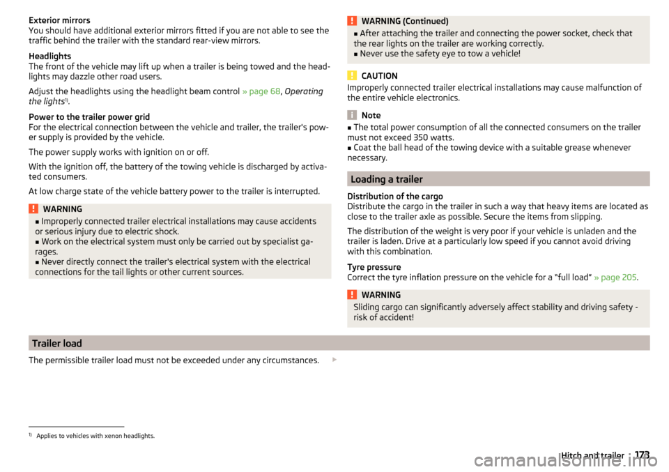
Attaching and detaching trailersFig. 197
Swivel out the 13-pin power
socket, safety eyelet
Connect and disconnect
›
Fit the ball rod.
›
Grip the 13-pin socket at point
A
and swing out in the direction of the arrow
» Fig. 197 .
›
Lift off protective cap
5
» Fig. 185 on page 167 .
›
Place the trailer onto the ball head.
›
Plug the trailer cable into 13-pin socket
A
» Fig. 197 .
If the trailer that is to be towed has a 7-pin connector, you can use a suitable
adapter from ŠKODA Original Accessories.
›
Hook the breakaway cable of the trailer to the security eyelet
B
.
The breakaway cable of the trailer must sag in all trailer positions relative to
the vehicle (sharp curves, reversing and the like).
Uncoupling takes place in reverse order.
172Driving
Page 175 of 268
Exterior mirrors
You should have additional exterior mirrors fitted if you are not able to see the
traffic behind the trailer with the standard rear-view mirrors.
Headlights
The front of the vehicle may lift up when a trailer is being towed and the head-
lights may dazzle other road users.
Adjust the headlights using the headlight beam control » page 68, Operating
the lights 1)
.
Power to the trailer power grid
For the electrical connection between the vehicle and trailer, the trailer's pow-
er supply is provided by the vehicle.
The power supply works with ignition on or off.
With the ignition off, the battery of the towing vehicle is discharged by activa-
ted consumers.
At low charge state of the vehicle battery power to the trailer is interrupted.WARNING■ Improperly connected trailer electrical installations may cause accidents
or serious injury due to electric shock.■
Work on the electrical system must only be carried out by specialist ga-
rages.
■
Never directly connect the trailer's electrical system with the electrical
connections for the tail lights or other current sources.
WARNING (Continued)■ After attaching the trailer and connecting the power socket, check that
the rear lights on the trailer are working correctly.■
Never use the safety eye to tow a vehicle!
CAUTION
Improperly connected trailer electrical installations may cause malfunction of
the entire vehicle electronics.
Note
■ The total power consumption of all the connected consumers on the trailer
must not exceed 350 watts.■
Coat the ball head of the towing device with a suitable grease whenever
necessary.
Loading a trailer
Distribution of the cargo
Distribute the cargo in the trailer in such a way that heavy items are located as
close to the trailer axle as possible. Secure the items from slipping.
The distribution of the weight is very poor if your vehicle is unladen and the
trailer is laden. Drive at a particularly low speed if you cannot avoid driving
with this combination.
Tyre pressure
Correct the tyre inflation pressure on the vehicle for a “full load” » page 205.
WARNINGSliding cargo can significantly adversely affect stability and driving safety -
risk of accident!
Trailer load
The permissible trailer load must not be exceeded under any circumstances. 1)
Applies to vehicles with xenon headlights.
173Hitch and trailer
Page 179 of 268
Brakes
Apply the brakes in good time! If the trailer is fitted with a trailer brake, apply
the brakes gently at first, then brake firmly. This will avoid brake jolts resulting
from the trailer wheels locking.
On downhill sections shift down a gear in good time to also use the engine as
a brake.WARNINGAlways drive particularly carefully with the trailer.
CAUTION
If you tow a trailer frequently, you should also have your vehicle inspected be-
tween service intervals.
Anti-theft alarm system
If the vehicle is locked, the alarm is activated when the electrical connection to
the trailer is interrupted.
Always switch off the anti-theft alarm system before a trailer is coupled or un-
coupled » page 58 .
Conditions for including a trailer in the anti-theft alarm system. The vehicle is factory-fitted with an anti-theft alarm system and a towing
device.
The trailer is electrically connected to the towing vehicle by means of the
trailer socket.
The electrical system of the vehicle and trailer is functional.
The vehicle is locked and the anti-theft alarm system is activated.
CAUTION
For technical reasons, trailers with rear LED lights cannot be connected to the
anti-theft alarm system.177Hitch and trailer