AUX SKODA OCTAVIA 2015 3.G / (5E) Owner's Manual
[x] Cancel search | Manufacturer: SKODA, Model Year: 2015, Model line: OCTAVIA, Model: SKODA OCTAVIA 2015 3.G / (5E)Pages: 268, PDF Size: 37.54 MB
Page 4 of 268
Table of Contents
On-board literature4
Notes
5
Structure and more information about the
Owner's Manual
6
Abbreviations
Safety
Passive Safety
8
General information
8
Correct and safe seated position
8
Seat belts
11
Using seat belts
11
Inertia reel and belt pretensioners
13
Airbag system
14
Description of the airbag system
14
Airbag overview
15
Deactivating airbags
19
Transporting children safely
20
Child seat
20
Fastening elements
23
Using the system
Cockpit
27
Overview
26
Instruments and warning lights
28
Instrument cluster
28
Warning lights
31
Information system
40
Driver information system
40
Driving data (Multifunction display)
41
MAXI DOT display
44Service interval display49SmartGate50
Unlocking and opening
53
Unlocking and locking
53
Anti-theft alarm system
58
Luggage compartment lid
59
Electric boot lid
60
Window operations
61
Panorama sliding/tilting roof
64
Lights and visibility
67
Lights
67
Interior lights
74
Visibility
76
Windscreen wipers and washers
77
Rear mirror
79
Seats and head restraints
81
Seats and head restraints
81
Seat features
85
Transporting and practical equipment
89
Useful equipment
89
Multimedia holder
99
Luggage compartment and transport of
cargo
100
Variable loading floor in the luggage
compartment (Estate)
107
Net partition
109
Roof rack
110
Heating and ventilation
112
Heating, manual air conditioning system,
Climatronic
112
Auxiliary heating (auxiliary heating and
ventilation)
117Driving
Starting-off and Driving120
Starting and stopping the engine using the
key
120
Starting and stopping the engine at the push
of the button
122
START-STOPsystem
124
Brakes and parking
126
Manual shifting of gears and pedals
128
Automatic gearbox
129
Running-in and economical driving
132
Avoiding damage to your vehicle
134
Assist systems
135
General information
135
Braking and stabilisation systems
135
OFF ROAD-mode
138
Parking aid (ParkPilot)
140
Rear View Camera
143
Park Assist
144
Cruise Control System
148
Adaptive Cruise Control (ACC)
150
Front Assist
155
Selection of the driving mode (Driving Mode
Selection)
157
Proactive passenger protection (Crew Protect
Assist)
160
Lane Departure Warning (Lane Assist)
160
Traffic sign recognition
162
Fatigue detection
164
Tyre pressure monitoring
165
Hitch and trailer
167
Hitch
167
Trailer
1722Table of Contents
Page 29 of 268
Using the system
Cockpit
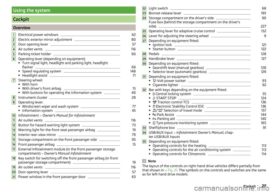
OverviewElectrical power windows
62
Electric exterior mirror adjustment
80
Door opening lever
57
Air outlet vents
116
Parking ticket holder
90
Operating lever (depending on equipment):
▶ Turn signal light, headlight and parking light, headlight
flasher
69
▶ Speed regulating system
148
▶Headlight assist
71
Steering wheel:
▶ With horn
▶ With driver’s front airbag
15
▶With buttons for operating the information system
40
Instrument cluster
28
Operating lever:
▶ Windscreen wiper and wash system
77
▶Information system
45
Infotainment » Owner's Manual for Infotainment
Air outlet vents
116
Button for hazard warning light system
73
Warning light for the front seat passenger airbag
19
Interior rear-view mirror
79
Storage compartment on the front passenger side
95
Front passenger airbag
15
External Infotainment module (in the front passenger storage
compartment) » Owner's Manual Infotainment
Key switch for switching off the front passenger airbag (in front
passenger storage compartment)
19
Air outlet vents
116
Door opening lever
57
Power window in the front passenger door
63123456789101112131415161718192021Light switch68
Bonnet release lever
195
Storage compartment on the driver's side
90
Fuse box (behind the storage compartment on the driver's
side)
227
Operating lever for adaptive cruise control
152
Lever for adjusting the steering wheel
9
Depending on equipment fitted:
▶ Ignition lock
121
▶Starter button
122
Pedals
128
Handbrake lever
127
Depending on equipment fitted:
▶ Gearshift lever (manual gearbox)
128
▶Selector lever (automatic gearbox)
129
Depending on equipment fitted:
▶ 12-Volt power socket
93
▶Cigarette lighter
92
Bar with keys depending on the equipment fitted:
▶ Central locking system
55
▶
START STOP
124
▶
Traction control TCS
136
▶
Electronic Stability Control ESC
136
▶
/
Selection of travel mode
157
▶
Park Assist
144
▶
Parking aid
140
▶
Tyre pressure monitoring system
165
Shelf/phone box
91
USB/AUX input
» Infotainment Owner's Manual , chap-
ter USB/AUX Inputs
Depending on equipment fitted:
▶ Operating controls for the heating
113
▶Operating controls for the air conditioning system
113
▶Operating controls for Climatronic
114
Note
The layout of the controls on right-hand drive vehicles differs partially from
that shown in » Fig. 21. The symbols on the controls and switches are the same
as for left-hand drive models.222324252627282930313233343527Cockpit
Page 91 of 268
WARNINGThe through-loading channel is only intended for transporting skis that are
placed in a properly secured, through-loading bag.Transporting and practical equipment
Useful equipment
Introduction
This chapter contains information on the following subjects:
Car park ticket holder
90
Storage compartment on the driver's side
90
stowage compartments in the doors
90
Storage compartment in the front centre console
91
Cup holders
91
Cigarette lighter
92
Ashtray
92
12-Volt power outlet
93
Waste container
93
Multimedia holder
94
Storage compartment under the front arm rest
95
Glasses compartment
95
Storage compartment on the front passenger side
95
Clothes hook
96
Storage pockets on the backs of the front seats
96
Storage compartment in the rear centre console
97
230-volt socket
97
Removable through-loading bag
98
AUX and USB inputs
99WARNING■ Do not place anything on the dash panel. These objects might slide or fall
down when driving (when accelerating, cornering or with an incorrect driv-
ing action) and may distract you from concentrating on the traffic – there is
the risk of an accident.■
When driving, ensure that no objects from the centre console or from oth-
er storage compartments can get into the driver's footwell. You would not
be able to brake, operate the clutch pedal or accelerate - danger of causing
an accident!
89Transporting and practical equipment
Page 101 of 268
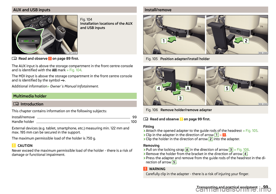
AUX and USB inputsFig. 104
Installation locations of the AUX
and USB inputs
Read and observe on page 89 first.
The AUX input is above the storage compartment in the front centre console and is identified with the mark
» Fig. 104 .
The MDI input is above the storage compartment in the front centre console
and is identified by the symbol .
Additional information » Owner´s Manual Infotainment .
Multimedia holder
Introduction
This chapter contains information on the following subjects:
Install/remove
99
Handle holder
100
External devices (e.g. tablet, smartphone, etc.) measuring min. 122 mm and
max. 195 mm can be secured in the support.
The maximum permissible load of the holder is 750 g.
CAUTION
Never exceed the maximum permissible load of the holder - there is a risk of
damage or functional impairment.Install/removeFig. 105
Position adapter/install holder
Fig. 106
Remove holder/remove adapter
Read and observe
on page 99 first.
Fitting
›
Attach the opened adapter to the guide rods of the headrest » Fig. 105.
›
Clip in the adapter in the direction of arrow
1
» .
›
Clip the holder in the direction of arrow
2
into the adapter.
Removing
›
Pull on the locking strap
A
in the direction of arrow
3
» Fig. 106 .
›
Remove the holder from the bracket in the direction of arrow
4
.
›
Press the adapter and remove from the guide rods of the headrest in the di-
rection of arrow
5
.
WARNINGCarefully clip in the adapter - there is a risk of injuring your finger.99Transporting and practical equipment
Page 115 of 268
WARNING■For your own safety and that of other road users, ensure that all the win-
dows are free of ice, snow and misting. The blower should always be on to
prevent the windows from misting up.■
Under certain circumstances, air at a temperature of about 5 °C can flow
out of the vents when the cooling system is switched on.
CAUTION
■ The air inlet in front of the windscreen must be free of e.g. ice, snow or
leaves to ensure that the heating and cooling system operates properly.■
After switching on the cooling Condensation from the evaporator of the air
conditioning may drip down and form a puddle below the vehicle. This is not a
leak!
■
If the coolant temperature is too high, the cooling system is switched off to
ensure that the engine cools down.
Heating and manual air conditioning
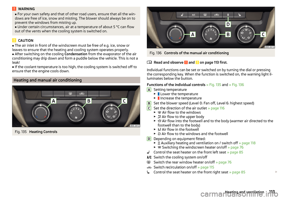
Fig. 135
Heating Controls
Fig. 136
Controls of the manual air conditioning
Read and observe
and on page 113 first.
Individual functions can be set or switched on by turning the dial or pressing
the corresponding key. When the function is switched on, the warning light il-
luminates below the button.
Functions of the individual controls » Fig. 135 and » Fig. 136
Setting temperature
▶ Lower the temperature
▶ Increase the temperature
Set the blower speed (Level 0: Fan off, Level 6: highest speed)
Set the direction of the air outlet » page 116
▶ Air flow to the windows
▶ Air flow to the upper body
▶ Air flow into the footwell and to the body (warmer air directed to the
footwell than to the body)
▶ Air flow in the footwell
▶ Air flow to the windows and the footwell
Depending on equipment fitted:
▶ Auxiliary heating and ventilation on / switch off
» page 118
▶ Switching the windscreen heater on/off
» page 76
Control the seat heater on the front left seat » page 85
Switch the cooling system on/off
Switch the rear window heater on/off » page 76
Switch recirculation on/off » page 115
Control the seat heater on the front right seat » page 85
ABCD113Heating and ventilation
Page 116 of 268
Information on the cooling system
The cooling system operates only if the following conditions are met
» page 112 .
The warning light below the button
» Fig. 136 illuminates after activation,
even if not all of the conditions for the function of the cooling system have
been met. The lighting up of the indicator light in the button signals the opera-
tional readiness of the cooling system.
When the air distribution control is turned to position
the cooling system is
activated.
Note
During operation of the manual air conditioning, an increase in engine idle
speed may occur under certain circumstances in order to ensure sufficient
heating comfort.
Climatronic (automatic air conditioning)
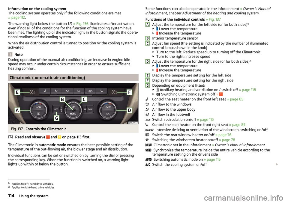
Fig. 137
Controls the Climatronic
Read and observe
and on page 113 first.
The Climatronic in automatic mode ensures the best-possible setting of the
temperature of the out-flowing air, the blower stage and air distribution.
Individual functions can be set or switched on by turning the dial or pressing
the corresponding key. When the function is switched on, a warning light
lights up within or below the button.
Some functions can also be operated in the infotainment » Owner´s Manual
Infotainment , chapter Adjustment of the heating and cooling system .
Functions of the individual controls » Fig. 137
Adjust the temperature for the left side (or for both sides) 1)
▶ Lower the temperature
▶ Increase the temperature
Interior temperature sensor
Adjust fan speed (the setting is indicated by the number of illuminated
control lamps shown in the knob) ▶ Turn to the left: Reduce speed up to turning off the Climatronic
▶ Turn to the right: Increase speed
Adjust the temperature for the right side (or for both sides) 2)
▶ Lower the temperature
▶ Increase the temperature
Display the temperature setting for the left side
Display the temperature setting for the right side
Depending on equipment fitted:
▶ Auxiliary heating and ventilation on / switch off
» page 118
▶ Switching Climatronic system off
»
Control the seat heater on the front left seat » page 85
Air flow to the windows
Air flow to the upper body
Air flow in the footwell
Switch recirculation on/off » page 115
Control the seat heater on the front right seat » page 85
Intensive de-icing or ventilation of the windscreen, switching on/off
Switch the rear window heater on/off » page 76
Switching the windscreen heater on/off » page 76
Climatronic set in the Infotainment » Owner´s Manual Infotainment
Synchronize the temperature inside the entire vehicle according to the
temperature setting on the driver's side
Switching automatic mode on » page 115
Switch the cooling system on/off
ABCDEFG1)
Applies to left-hand drive vehicles.
2)
Applies to right-hand drive vehicles.
114Using the system
Page 119 of 268
Opening›Turn regulator B » Fig. 138 or » Fig. 139 upwards.
Closing›
Turn regulator
B
» Fig. 138 or » Fig. 139 downwards.
Depending on the setting of the air distribution on the front panel of the heat-
er, the manual air conditioning or the Climatronic, the following air vents are
active.
Set the direction of the air outletActive air outlet nozzles » Fig. 138 and
» Fig. 139 1. 2 . 41. 2 . 4 . 5 . 7 3. 4 . 64 . 5 . 73 . 4 . 5 . 6 . 7
CAUTION
To ensure that the heating, the manual air conditioning and the Climatronic
systems work properly, do not block up the air outlet vents with any objects.
Auxiliary heating (auxiliary heating and ventilation)
Introduction
This chapter contains information on the following subjects:
Switching on/off
118
Radio remote control
119
Functional requirements of the auxiliary heating (auxiliary heating and ventila-
tion)
The charge state of the vehicle battery is sufficient.
The fuel supply is adequate (the warning light is not illuminated in the
instrument cluster).
Aux. heating
The auxiliary heating can be used when both when stationary, when the en-
gine is switched off, to preheat the vehicle and also while driving (e.g. during
the heating phase of the engine).
The auxiliary heating warms up the coolant by combusting fuel from the vehi-
cle tank. This heats the air flowing into the passenger compartment (if the
blower is turned on).
The auxiliary heating also warms up the engine.
Auxiliary ventilation
The auxiliary ventilation enables fresh air to flow into the vehicle interior by
switching off the engine, whereby the interior temperature is effectively de-
creased (e.g. with the vehicle parked in the sun).WARNING■ The auxiliary heating (auxiliary heating and ventilation) (hereinafter refer-
red to as aux. heating) must never be operated in closed rooms (e.g. garag-
es) – risk of poisoning!■
The auxiliary heating must not be allowed to run during refuelling – risk
of fire.
■
The exhaust pipe of the auxiliary heating is located on the underside of
the vehicle. If you want to use the heater, do not park the car in places
where the exhaust fumes can come into contact with flammable materials
such as dry grass, undergrowth, leaves, spilled fuel etc. - risk of fire.
CAUTION
■ The exhaust pipe of the auxiliary heating, which is located on the underside
of the vehicle, must not be clogged and the exhaust flow must not be blocked.■
If the auxiliary heating is running, the vehicle battery discharges.
■
The air inlet in front of the windscreen must be free (e.g. of ice, snow or
leaves) to ensure that the auxiliary heating operates properly.
117Heating and ventilation
Page 120 of 268
Note■The auxiliary heating only switches the blower on, if it has achieved a coolant
temperature of approx. 50 °C.■
At low outside temperatures, this can result in a formation of water vapour in
the area of the engine compartment. This is quite normal and is not an operat-
ing problem.
■
So that warm air can flow into the vehicle interior after switching on the aux.
heating, you must maintain the comfort temperature normally selected by you,
leave the fan switched on and leave the air outlet vents in open. It is recom-
mended to put the air flow in the position
or
.
Switching on/off
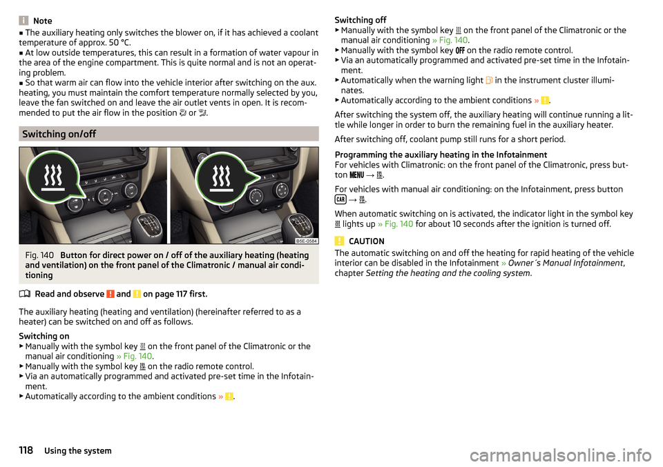
Fig. 140
Button for direct power on / off of the auxiliary heating (heating
and ventilation) on the front panel of the Climatronic / manual air condi-
tioning
Read and observe
and on page 117 first.
The auxiliary heating (heating and ventilation) (hereinafter referred to as a
heater) can be switched on and off as follows.
Switching on
▶ Manually with the symbol key on the front panel of the Climatronic or the
manual air conditioning » Fig. 140.
▶ Manually with the symbol key on the radio remote control.
▶ Via an automatically programmed and activated pre-set time in the Infotain-
ment.
▶ Automatically according to the ambient conditions »
.
Switching off
▶ Manually with the symbol key on the front panel of the Climatronic or the
manual air conditioning » Fig. 140.
▶ Manually with the symbol key
on the radio remote control.
▶ Via an automatically programmed and activated pre-set time in the Infotain-
ment.
▶ Automatically when the warning light
in the instrument cluster illumi-
nates.
▶ Automatically according to the ambient conditions »
.
After switching the system off, the auxiliary heating will continue running a lit-
tle while longer in order to burn the remaining fuel in the auxiliary heater.
After switching off, coolant pump still runs for a short period.
Programming the auxiliary heating in the Infotainment
For vehicles with Climatronic: on the front panel of the Climatronic, press but-
ton
→
.
For vehicles with manual air conditioning: on the Infotainment, press button
→
.
When automatic switching on is activated, the indicator light in the symbol key
lights up
» Fig. 140 for about 10 seconds after the ignition is turned off.
CAUTION
The automatic switching on and off the heating for rapid heating of the vehicle
interior can be disabled in the Infotainment » Owner´s Manual Infotainment ,
chapter Setting the heating and the cooling system .118Using the system
Page 121 of 268
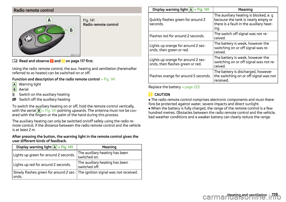
Radio remote controlFig. 141
Radio remote control
Read and observe and on page 117 first.
Using the radio remote control, the aux. heating and ventilation (hereinafterreferred to as heater) can be switched on or off.
Function and description of the radio remote control » Fig. 141
Warning light
Aerial
Switch on the auxiliary heating
Switch off the auxiliary heating
To switch the auxiliary heating on or off, hold the remote control vertically,
with the aerial
B
» Fig. 141 pointing upwards. The antenna must not be cov-
ered with the fingers or the palm of the hand during this process.
The auxiliary heating can only be switched on/off safely using the radio re-
mote control, if the distance between the radio remote control and the vehicle
is at least 2 m.
After pressing the button, the warning light in the remote control gives the
user different kinds of feedback.
Display warning light A » Fig. 141MeaningLights up green for around 2 seconds.The auxiliary heating has been
switched on.Lights up red for around 2 seconds.The auxiliary heating has been
switched off.Slowly flashes green for around 2 sec-
onds.The ignition signal was not received.ABDisplay warning light A » Fig. 141MeaningQuickly flashes green for around 2
seconds.The auxiliary heating is blocked, e. g
because the tank is nearly empty or
there is a fault in the auxiliary heat-
ing.Flashes red for around 2 seconds.The switch off signal was not re-
ceived.Lights up orange for around 2 sec-
onds, then green or red.The battery is weak, however the
switching on or off signal was re-
ceived.Lights up orange for around 2 sec-
onds, then flashes green or red.The battery is weak, however the
switching on or off signal was not re-
ceived.Flashes orange for around 5 seconds.The battery is discharged, however
the switching on or off signal was not
received.
Replace the battery » page 223.
CAUTION
■
The radio remote control comprises electronic components and must there-
fore be protected against water, severe impacts and direct sunlight.■
When the battery is fully charged, the range of the remote control is a few
hundred metres. Obstacles between the radio remote control and the vehicle,
bad weather conditions and a weaker battery can clearly reduce the range.
119Heating and ventilation
Page 137 of 268
Assist systems
General information
Introduction
This chapter contains information on the following subjects:
Radar sensor
135WARNINGThe following general information regarding the use of assistance systems
must be observed.■
The assistance systems only serve to support and do not relieve the driv-
er of the responsibility for driving the vehicle.
■
The increased safety provision, as well as the increased occupant protec-
tion provided by the assistance systems must not tempt you to take risks -
risk of accident!
■
Adjust the speed and driving style to the current visibility, weather, road
and traffic conditions.
■
The assistance systems have physical and system-related limitations. For
this reason, the driver may experience some undesired or delayed system
responses in certain situations. You should therefore always be alert and
ready to intervene!
■
Only activate, deactivate or set the assistance systems so that you have
the vehicle fully under control in every traffic situation - risk of accident!
Radar sensor
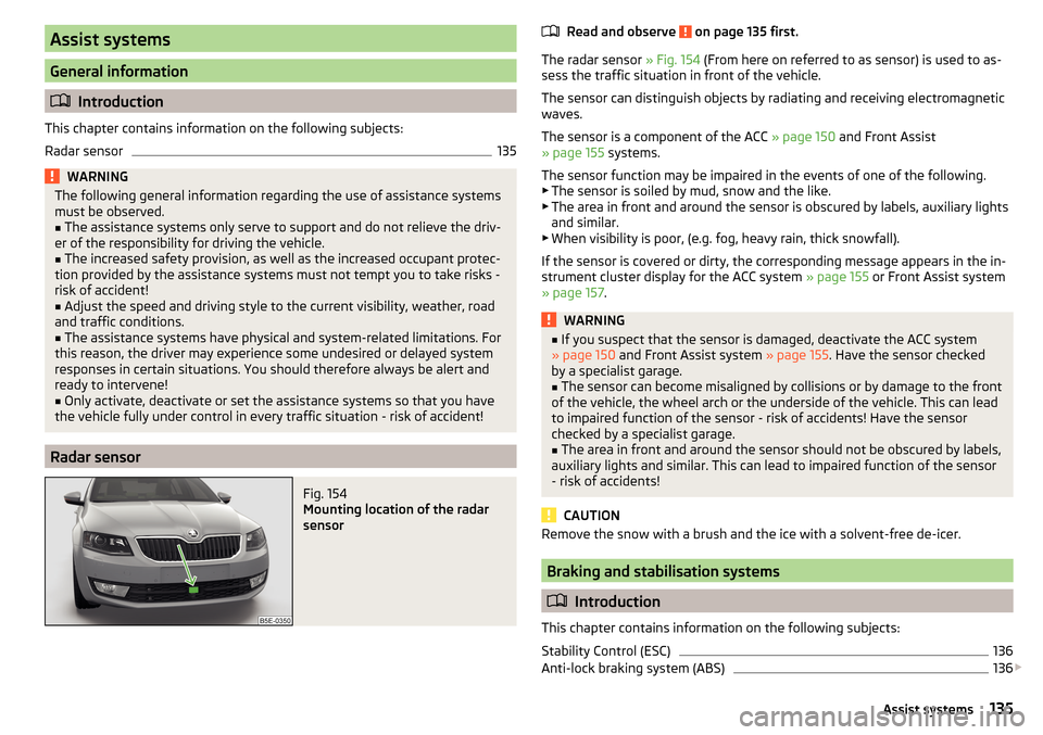
Fig. 154
Mounting location of the radar
sensor
Read and observe on page 135 first.
The radar sensor » Fig. 154 (From here on referred to as sensor) is used to as-
sess the traffic situation in front of the vehicle.
The sensor can distinguish objects by radiating and receiving electromagnetic waves.
The sensor is a component of the ACC » page 150 and Front Assist
» page 155 systems.
The sensor function may be impaired in the events of one of the following. ▶ The sensor is soiled by mud, snow and the like.
▶ The area in front and around the sensor is obscured by labels, auxiliary lights
and similar.
▶ When visibility is poor, (e.g. fog, heavy rain, thick snowfall).
If the sensor is covered or dirty, the corresponding message appears in the in-
strument cluster display for the ACC system » page 155 or Front Assist system
» page 157 .
WARNING■
If you suspect that the sensor is damaged, deactivate the ACC system
» page 150 and Front Assist system » page 155. Have the sensor checked
by a specialist garage.■
The sensor can become misaligned by collisions or by damage to the front
of the vehicle, the wheel arch or the underside of the vehicle. This can lead
to impaired function of the sensor - risk of accidents! Have the sensor
checked by a specialist garage.
■
The area in front and around the sensor should not be obscured by labels,
auxiliary lights and similar. This can lead to impaired function of the sensor
- risk of accidents!
CAUTION
Remove the snow with a brush and the ice with a solvent-free de-icer.
Braking and stabilisation systems
Introduction
This chapter contains information on the following subjects:
Stability Control (ESC)
136
Anti-lock braking system (ABS)
136
135Assist systems