air condition SKODA OCTAVIA 2015 3.G / (5E) Owner's Manual
[x] Cancel search | Manufacturer: SKODA, Model Year: 2015, Model line: OCTAVIA, Model: SKODA OCTAVIA 2015 3.G / (5E)Pages: 268, PDF Size: 37.54 MB
Page 4 of 268
Table of Contents
On-board literature4
Notes
5
Structure and more information about the
Owner's Manual
6
Abbreviations
Safety
Passive Safety
8
General information
8
Correct and safe seated position
8
Seat belts
11
Using seat belts
11
Inertia reel and belt pretensioners
13
Airbag system
14
Description of the airbag system
14
Airbag overview
15
Deactivating airbags
19
Transporting children safely
20
Child seat
20
Fastening elements
23
Using the system
Cockpit
27
Overview
26
Instruments and warning lights
28
Instrument cluster
28
Warning lights
31
Information system
40
Driver information system
40
Driving data (Multifunction display)
41
MAXI DOT display
44Service interval display49SmartGate50
Unlocking and opening
53
Unlocking and locking
53
Anti-theft alarm system
58
Luggage compartment lid
59
Electric boot lid
60
Window operations
61
Panorama sliding/tilting roof
64
Lights and visibility
67
Lights
67
Interior lights
74
Visibility
76
Windscreen wipers and washers
77
Rear mirror
79
Seats and head restraints
81
Seats and head restraints
81
Seat features
85
Transporting and practical equipment
89
Useful equipment
89
Multimedia holder
99
Luggage compartment and transport of
cargo
100
Variable loading floor in the luggage
compartment (Estate)
107
Net partition
109
Roof rack
110
Heating and ventilation
112
Heating, manual air conditioning system,
Climatronic
112
Auxiliary heating (auxiliary heating and
ventilation)
117Driving
Starting-off and Driving120
Starting and stopping the engine using the
key
120
Starting and stopping the engine at the push
of the button
122
START-STOPsystem
124
Brakes and parking
126
Manual shifting of gears and pedals
128
Automatic gearbox
129
Running-in and economical driving
132
Avoiding damage to your vehicle
134
Assist systems
135
General information
135
Braking and stabilisation systems
135
OFF ROAD-mode
138
Parking aid (ParkPilot)
140
Rear View Camera
143
Park Assist
144
Cruise Control System
148
Adaptive Cruise Control (ACC)
150
Front Assist
155
Selection of the driving mode (Driving Mode
Selection)
157
Proactive passenger protection (Crew Protect
Assist)
160
Lane Departure Warning (Lane Assist)
160
Traffic sign recognition
162
Fatigue detection
164
Tyre pressure monitoring
165
Hitch and trailer
167
Hitch
167
Trailer
1722Table of Contents
Page 10 of 268
Safety
Passive Safety
General information
Introduction
This chapter contains information on the following subjects:
Before setting off
8
Driving safety
8
In this section of the instructions you will find important information, tips and
notes on the subject of passive safety.
We have combined everything here which you should be familiar with, for ex-
ample, regarding seat belts, airbags, safety of children and anything similar.
You will find further information on safety, which concerns you and those trav-
elling with you, in the following chapters of this Owner's Manual.
The complete on-board literature should therefore always be in the vehicle.
This applies in particular, if you rent out or sell the vehicle.
Before setting off
For your own safety and the safety of the people travelling with you, please
pay attention to the following points before setting off.
▶ Ensure that the lighting and the turn signal system are functioning properly.
▶ Ensure that the function of the wipers and the condition of the wiper blades
are free of any defects.
▶ Ensure that all of the windows offer good visibility to the outside.
▶ Adjust the rear-view mirror so that vision to the rear is guaranteed.
▶ Ensure that the mirrors are not covered.
▶ Check the tyre inflation pressure.
▶ Check the engine oil, brake fluid and coolant level.
▶ Secure all items of luggage.
▶ Do not exceed the permissible axle loads and permissible gross weight of the
vehicle.
▶ Close all doors as well as the bonnet and boot lid.
▶ Ensure that no objects can obstruct the pedals.
▶
Protect children in suitable child seats with correctly fastened seat belts
» page 20 , Transporting children safely .
▶ Adopt the correct seated position » page 8, Correct and safe seated posi-
tion . Tell your passengers to assume the correct seated position.
Driving safety
The driver is fully responsible for himself and passengers, especially children. If
your driving safety is effected, you place yourself and the oncoming traffic at
risk.
The following guidelines must therefore be observed. ▶ Do not become distracted from concentrating on the traffic situation, (e.g. by
your passengers or mobile phone calls).
▶ Never drive when your driving ability is impaired, (e.g. due to medication, al-
cohol or drugs).
▶ Keep to the traffic regulations and the permissible speed limit.
▶ Always adjust the driving speed to the road, traffic and weather conditions.
▶ Take regular breaks on long journeys (at least every two hours).
The following list contains instructions for the Passenger which, if not ob-
served, may cause serious injuries or death. ▶ Do not lean against the dash panel.
▶ Do not put your feet on the dash panel.
The following list contains instructions for all Passengers which, if not ob-
served, may cause serious injuries or death. ▶ Do not sit only on the front area of the seat.
▶ Do not sit facing to the side.
▶ Do not lean out of the window.
▶ Do not put your limbs out of the window.
▶ Do not put your feet on the seat upholstery.
Correct and safe seated position
Introduction
This chapter contains information on the following subjects:
Correct seat position of the driver
9
Adjusting the steering wheel position
9
Correct seated position for the front passenger
10
Correct seated position for the passengers in the rear seats
10
8Safety
Page 17 of 268
System descriptionRead and observe
on page 14 first.
The inflation of the airbag is carried out in a fraction of a second.
When the airbags are deployed they fill with gas and inflate.
A grey white or red, non-harmful gas is released when the airbag is inflated.
This is perfectly normal and is not an indication of a fire in the vehicle.
Depending on the vehicle equipment, the airbag system consists of the
following parts. ▶ Front airbag for the driver and the front passenger » page 15.
▶ Driver’s knee airbag » page 17.
▶ Side airbags » page 17.
▶ Head airbags » page 18.
▶ Airbag warning light in the instrument cluster » page 35.
▶ Key switch for the front passenger airbag » page 19.
▶ Warning light for the front passenger airbag in the middle of the dash panel
» page 19 .
Airbag deployment
Read and observe
on page 14 first.
The airbag system is only functional when the ignition is switched on.
Triggering conditions
It is not possible to generally determine which deployment conditions apply to
the airbag system in every situation. An important role is played by factors
such as the type of object that the vehicle hits (hard/soft), the impact angle, vehicle speed, etc.
A decisive factor for the deployment of the airbags is the deceleration which
occurs. If the vehicle deceleration which occurs and is measured during the
collision remains below the prescribed reference values specified in the control
unit, the airbags are not deployed although the vehicle may well suffer severe
damage to the bodywork as a consequence of the accident.
The following airbags will be deployed in the event of a severe frontal
collision.
▶ Driver’s front airbag.
▶ Front passenger airbag.
▶ Driver’s knee airbag.
The following airbags will be deployed in the event of a severe side collision.
▶ Front side airbag on the side of the accident.
▶ Rear side airbag on the side of the accident.
▶ Head airbags on the side of the accident.
When an airbag is deployed, the following occurs.
▶ The interior light comes on (if the automatic operation of the interior light is
switched on - switch
).
▶ The hazard warning lights are switched on.
▶ All the doors are unlocked.
▶ The fuel supply to the engine is interrupted.
When there is no air bag deployment?
With minor frontal and side collisions, rear collision, overturning of the vehicle
or vehicle roll-over there is no airbag deployment.
Airbag overview
Introduction
This chapter contains information on the following subjects:
Front airbags
15
Driver’s knee airbag
17
Side airbags
17
Head airbags
18
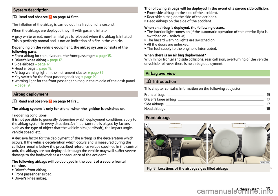
Front airbags
Fig. 8
Locations of the airbags / gas filled airbags
15Airbag system
Page 20 of 268
WARNINGInformation on correct seated position■Your head should never be positioned in the deployment area of the side
airbag. You might suffer severe injuries in the event of an accident. This ap-
plies in particular to children who are transported without using a suitable
child safety seat » page 22, Child safety and side airbag .■
There must not be any further persons, animals or objects positioned be-
tween the occupants and the deployment area of the airbag. No accesso-
ries, such as cup holders, should be attached to the doors.
■
If children adopt an incorrect seated position when travelling, they may
be exposed to an increased risk of injury in the event of an accident. This
can result in serious injuries » page 20, Child seat .
WARNING■
Do not place any objects within the deployment area of the side airbags –
risk of injury!■
The airbag system operates using pressure sensors located in the front
doors. For this reason, no adjustments may be carried out to the doors or
door panels (e.g. installation of additional loudspeakers). Further informa-
tion » page 180 , Airbags .
■
Ensure that there are no excessive forces, such as violent knocks, kicks
etc., impact on the backrests of the seats otherwise the system may be
damaged. The side airbags would not be deployed in such a case!
■
Any seat or protective covers which you fit to the driver or front passen-
ger seats must only be of the type expressly authorized by ŠKODA. In view
of the fact that the airbag inflates out of the backrest of the seat, use of
non-approved seat or protective covers would considerably impair the pro-
tective function of the side airbag.
■
Any damage to the original seat covers in the area of the side airbag mod-
ule must be repaired immediately by a specialist garage.
■
The airbag modules in the front seats must not display any damage,
cracks or deep scratches. It is not permissible to use force in order to open
the modules.
Note
■ In vehicles with side front airbags, a label with the text is located on
the front seat backrests.■
In vehicles with rear side airbags, the text
can be seen between the en-
trance area and the rear seat rest.
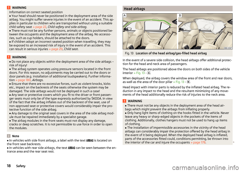
Head airbagsFig. 13
Location of the head airbag/gas-filled head airbag
In the event of a severe side collision, the head airbags offer additional protec-
tion for the head and neck area of passengers.
The head airbags are positioned above the doors on both sides of the vehicle
interior » Fig. 13 -
.
When deployed, the airbag covers the window area of the front and rear doors,
as well as the area of the door pillar » Fig. 13 -
.
Head impact with interior parts is reduced by the inflated head airbag. The re-
duction in any impact to the head and the resultant minimizing of any move-
ments of the head additionally reduce the risk of injuries to the neck area.
WARNING■ There must not be any objects in the deployment area of the head air-
bags which might prevent the airbags from inflating properly.■
Only hang light items of clothing on the hooks fitted in the vehicle. Never
leave any heavy or sharp-edged objects in the pockets of the items of
clothing. Additionally, clothes hangers must not be used to hang up items
of clothing.
■
The installation of impermissible accessories in the vicinity of the head
airbags can considerably impair the protection offered by the head airbag in
the event of it being deployed. When the deployed head airbag is inflated,
parts of the accessories fitted could, conditions permitting, be thrown into
the interior of the car and injure the occupants » page 178.
18Safety
Page 22 of 268
›Check that the warning light
underneath the text
» Fig. 14 - lights up after the ignition is switched on.
Switching on›
Switch off the ignition.
›
Open the storage box on the front passenger's side.
›
Fold the key bit out completely for the radio key » .
›
Carefully insert the key into the key slot in the key switch as far as the stop.
›
Use the key to turn the slot of the key switch » Fig. 14
carefully into the
position
.
›
Pull the key out of the slot in the key switch » .
›
Close the storage box on the front passenger's side.
›
Check that the warning light
underneath the text
» Fig. 14
- lights up after the ignition is switched on.
The
warning light goes out 65 seconds after the key switch status has
changed or after the ignition is switched on.
WARNING■ The driver is responsible for whether the airbag is switched on or switch-
ed off.■
Only switch off the airbag when the ignition is switched off! Otherwise a
fault can occur in the system for deactivating the airbag.
■
If the warning lights
flash, the front passenger airbag will not
be deployed in the event of an accident! Have the airbag system checked
by a specialist garage immediately.
■
Do not leave the key inserted in the key-operated switch while driving -
vibrations can cause the key to turn in the slot and switch on the airbag!
The airbag could be triggered unexpectedly in an accident - it may result in
injury or death!
CAUTION
An insufficiently folded out key bit can damage the key switch!Transporting children safely
Child seat
Introduction
This chapter contains information on the following subjects:
Use of a child seat on the front passenger seat
21
Use of the child seat on the front passenger seat
22
Child safety and side airbag
22
Classification of child seats
22
Use of child seats fastened with a seat belt
22
To avoid serious injury or death children are always to be in an appropriate
child safety seat with regards to height, weight, and age.
For safety reasons, we recommend that you always transport child seats on the rear seats.
Child seats complying with the ECE-R 44 Economic Commission for Europe
standard must be used.
Child seats that comply with the ECE-R 44 standard have a test seal that can-
not be removed: a large E within a circle with the test number below.
With child safety seats in groups 2 and 3, make sure that the loop-around fit-
tings attached to the child seat headrest is positioned in front of or at the
same height as the loop-around fittings on the B pillar on the passenger side.
WARNING■ One should never carry children, and also not babies! - on one's lap.■Never leave children unattended in the vehicle. Certain outside climatic
conditions can cause life-threatening temperatures in the vehicle.■
The child must be secured in the vehicle during the entire travelling time!
Otherwise, in the event of an accident, the child would be thrown through
the vehicle and as a result may suffer fatal injuries, and also injure other oc-
cupants.
20Safety
Page 29 of 268
Using the system
Cockpit
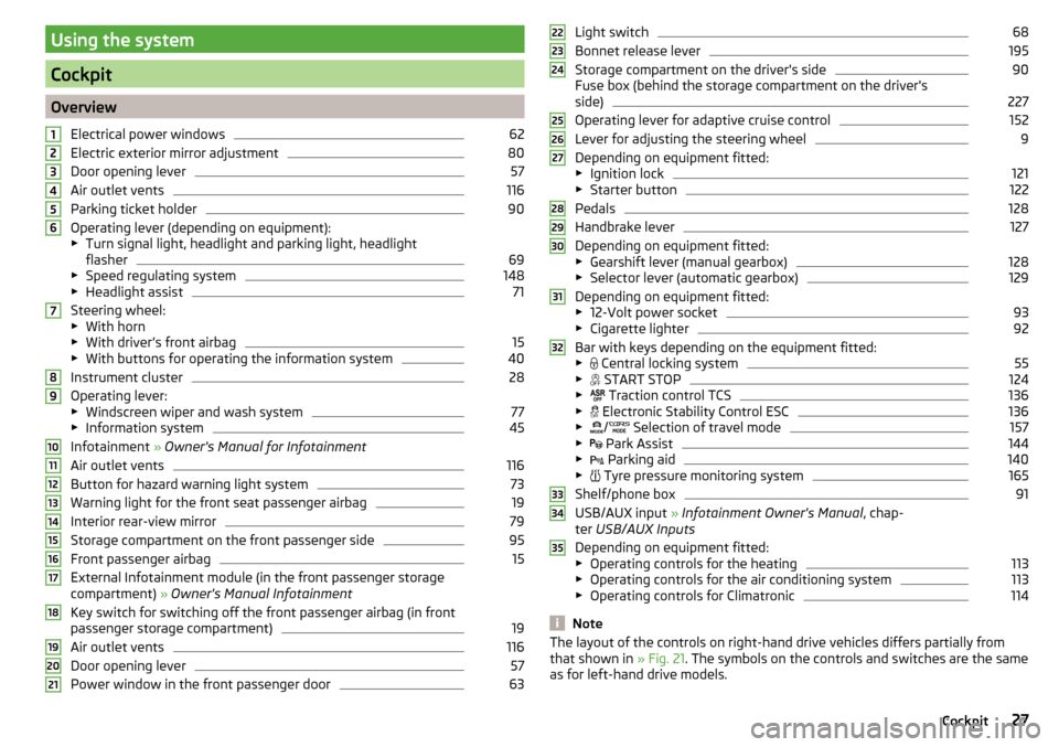
OverviewElectrical power windows
62
Electric exterior mirror adjustment
80
Door opening lever
57
Air outlet vents
116
Parking ticket holder
90
Operating lever (depending on equipment):
▶ Turn signal light, headlight and parking light, headlight
flasher
69
▶ Speed regulating system
148
▶Headlight assist
71
Steering wheel:
▶ With horn
▶ With driver’s front airbag
15
▶With buttons for operating the information system
40
Instrument cluster
28
Operating lever:
▶ Windscreen wiper and wash system
77
▶Information system
45
Infotainment » Owner's Manual for Infotainment
Air outlet vents
116
Button for hazard warning light system
73
Warning light for the front seat passenger airbag
19
Interior rear-view mirror
79
Storage compartment on the front passenger side
95
Front passenger airbag
15
External Infotainment module (in the front passenger storage
compartment) » Owner's Manual Infotainment
Key switch for switching off the front passenger airbag (in front
passenger storage compartment)
19
Air outlet vents
116
Door opening lever
57
Power window in the front passenger door
63123456789101112131415161718192021Light switch68
Bonnet release lever
195
Storage compartment on the driver's side
90
Fuse box (behind the storage compartment on the driver's
side)
227
Operating lever for adaptive cruise control
152
Lever for adjusting the steering wheel
9
Depending on equipment fitted:
▶ Ignition lock
121
▶Starter button
122
Pedals
128
Handbrake lever
127
Depending on equipment fitted:
▶ Gearshift lever (manual gearbox)
128
▶Selector lever (automatic gearbox)
129
Depending on equipment fitted:
▶ 12-Volt power socket
93
▶Cigarette lighter
92
Bar with keys depending on the equipment fitted:
▶ Central locking system
55
▶
START STOP
124
▶
Traction control TCS
136
▶
Electronic Stability Control ESC
136
▶
/
Selection of travel mode
157
▶
Park Assist
144
▶
Parking aid
140
▶
Tyre pressure monitoring system
165
Shelf/phone box
91
USB/AUX input
» Infotainment Owner's Manual , chap-
ter USB/AUX Inputs
Depending on equipment fitted:
▶ Operating controls for the heating
113
▶Operating controls for the air conditioning system
113
▶Operating controls for Climatronic
114
Note
The layout of the controls on right-hand drive vehicles differs partially from
that shown in » Fig. 21. The symbols on the controls and switches are the same
as for left-hand drive models.222324252627282930313233343527Cockpit
Page 45 of 268
Current driving speed
The display is identical to the display on the speedometer.
Average speed
The indication is calculated continuously since the last deletion of the memory.
After erasing the memory, no data will appear for the first 300 m driven.
Distance travelled
The distance travelled since the memory was last erased is displayed.
The maximum distance indicated is 9999 km. The indicator is automatically set
back to zero if this period is exceeded.
Driving time
The time travelled since the memory was last erased is displayed.
The maximum distance indicated is 99 hours and 59 minutes. The indicator is
automatically set back to zero if this period is exceeded.
Convenience consumers
There, the total consumption of all consumer comfort in l / h is displayed.
Along with the consumption data, a list of the three consumers with the larg-
est share of fuel consumption (e.g. air conditioning and similar devices) is dis-
played.
Refuelling amount 1)
After the consumption of about 10 litres of fuel from the fully refuelled tank, an amount of fuel is displayed in l. This amount can now be safely refilled.
Natural gas quality
The details of the quality of natural gas are displayed as a percentage of be-
tween 70% to 100%.
The higher the value of natural gas, the lower is the consumption.
Coolant temperature
If the coolant temperature is in the range 80-110 °C, the engine operating tem-
perature is reached.
If the temperature lies below 80 °C or above 110 °C, avoid high engine revs, full
throttle and high engine loads.Warning when exceeding the set speed
Read and observe
on page 41 first.
The system offers the possibility to set a speed limit beyond which an audible
alarm will sound and the following warning message appears.
Speed ... exceeded.SPEED TOO HIGH
Adjust the speed limit while the vehicle is stationary
›
Select the menu item
Warning at
at (
) or
(
) and confirm.
›
Set the desired speed limit.
›
Confirm the set value, or wait several seconds; your settings will be saved
automatically.
The speed limit can be set in 5 km/h intervals.
Adjusting the speed limit while the vehicle is moving
›
Select the menu item
Warning at
at ( ) or
(
) and confirm.
›
Drive at the desired speed.
›
Confirm the current speed as the speed limit.
The set speed limit can be manually adjusted later if needed.
Deactivate speed limit
›
Select the menu item
Warning at
at ( ) or
(
) and confirm.
›
Confirm the stored value of the speed limits.
The speed limit will be disabled.
The speed limit set mode is stored even after the ignition is switched off and
on. After a gap between driving exceeding 2 hours, the pre-set speed limit is
deactivated.
1)
Only valid for some countries.
43Information system
Page 51 of 268
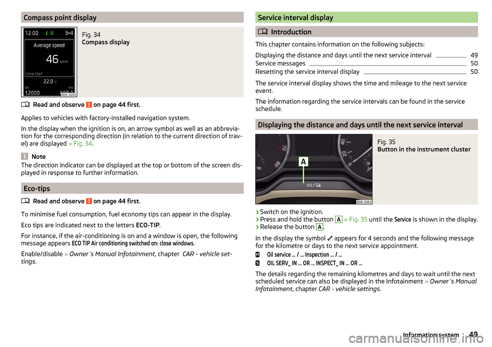
Compass point displayFig. 34
Compass display
Read and observe on page 44 first.
Applies to vehicles with factory-installed navigation system.
In the display when the ignition is on, an arrow symbol as well as an abbrevia- tion for the corresponding direction (in relation to the current direction of trav-
el) are displayed » Fig. 34.
Note
The direction indicator can be displayed at the top or bottom of the screen dis-
played in response to further information.
Eco-tips
Read and observe
on page 44 first.
To minimise fuel consumption, fuel economy tips can appear in the display.
Eco tips are indicated next to the letters ECO-TIP.
For instance, if the air-conditioning is on and a window is open, the following
message appears
ECO TIP Air conditioning switched on: close windows.
Enable/disable » Owner´s Manual Infotainment , chapter CAR - vehicle set-
tings .
Service interval display
Introduction
This chapter contains information on the following subjects:
Displaying the distance and days until the next service interval
49
Service messages
50
Resetting the service interval display
50
The service interval display shows the time and mileage to the next service
event.
The information regarding the service intervals can be found in the service
schedule.
Displaying the distance and days until the next service interval
Fig. 35
Button in the instrument cluster
›
Switch on the ignition.
›
Press and hold the button
A
» Fig. 35 until the
Service
is shown in the display.
›
Release the button
A
.
In the display the symbol appears for 4 seconds and the following message
for the kilometre or days to the next service appointment.
Oil service … / … Inspection … / …OIL SERV_ IN … OR … INSPECT_ IN … OR …
The details regarding the remaining kilometres and days to wait until the next
scheduled service can also be displayed in the Infotainment » Owner´s Manual
Infotainment , chapter CAR - vehicle settings .
49Information system
Page 52 of 268
Service messages
Messages before reaching the scheduled service date
Before the next service date has been reached, after switching on the ignition,
the symbol
as well as a message about the mileage or days until the next
service event appears in the display.
Messages upon reaching scheduled service date
Once the service interval is reached, the icon
appears in the display after the
ignition is switched on, as well as the following message, for example.Oil service now!OIL SERVICE NOW
or
Inspection now!INSPECTION NOW
or
Oil service and inspection now!OIL SERVICE + INSP_ NOW
Resetting the service interval display
We recommend that the display reset is completed by a specialist garage.
We recommend that you do not reset the service interval display yourself. In-
correctly setting the service interval display could cause problems to the vehi-
cle.
Variable service interval
For vehicles with variable service intervals, after resetting the oil change serv-
ice display in a specialist garage, the values of the new service interval are dis-
played, which are based on the previous operating conditions of the vehicle.
These values are then continuously matched according to the actual operating
conditions of the vehicle.
SmartGate
Introduction
Fig. 36
ŠKODA websites
This chapter contains information on the following subjects:
Connection to SmartGate using Wi-Fi
51
Connection to SmartGate using Wi-Fi Direct
51
SmartGate web interface
52
Password/PIN code change
52
SmartGate is a system that transmits certain driving data (such as fuel con-
sumption, speed or similar) via Wi-Fi and Wi-Fi Direct.
The ŠKODA compatible communications device (e.g. phone, tablet, notebook)
offer the possibility to further transmit the received data.
More information on available applications, a list of compatible communication
devices and on SmartGate can be found on the ŠKODA website » Fig. 36.
http://www.skoda-auto.com
WARNING■ The general binding country-specific regulations for operating communi-
cation devices in the vehicle must be observed.■
Never leave a communication device in the deployment area of an airbag,
on a seat, on the dash panel or any another area, from which it can be
thrown during a sudden braking manoeuvre, an accident or a collision - risk
of injury!
■
Never connect or disconnect a communication device while driving - risk
of accident!
50Using the system
Page 64 of 268
The windows can be operated electrically from the following locations; all win-
dows from the driver's seat and also via the buttons for the windows in the
passenger door or the rear doors.WARNINGThe windows should be closed carefully – risk of injury!
CAUTION
■ In the event that the windows are frozen, first of all remove the ice
» page 184 , Windows and external mirrors and only then operate the window
lift. Otherwise, the window sealing and the window lift mechanism could be
damaged.■
Make sure that the windows are closed whenever you leave the locked vehi-
cle.
For the sake of the environment
At high speeds, you should keep the windows closed to prevent unnecessarily high fuel consumption.
Note
When driving always use the existing heating, air conditioning and ventilation
system for ventilating the interior of the vehicle. If the windows are opened,
dust as well as other dirt can get into the vehicle and in addition the wind
noise is more at certain speeds.
Mechanical window lefter
Fig. 47
Window operation: left/right
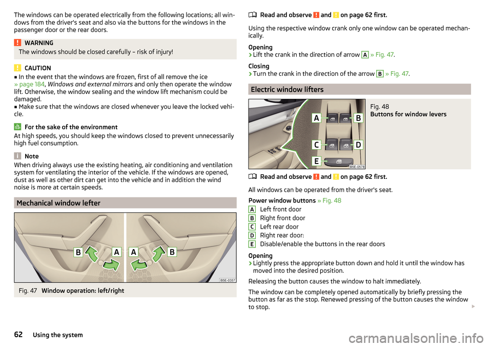
Read and observe and on page 62 first.
Using the respective window crank only one window can be operated mechan-
ically.
Opening
›
Lift the crank in the direction of arrow
A
» Fig. 47 .
Closing
›
Turn the crank in the direction of the arrow
B
» Fig. 47 .
Electric window lifters
Fig. 48
Buttons for window levers
Read and observe and on page 62 first.
All windows can be operated from the driver's seat.
Power window buttons » Fig. 48
Left front door
Right front door
Left rear door
Right rear door:
Disable/enable the buttons in the rear doors
Opening
›
Lightly press the appropriate button down and hold it until the window has
moved into the desired position.
Releasing the button causes the window to halt immediately.
The window can be completely opened automatically by briefly pressing the
button as far as the stop. Renewed pressing of the button causes the window
to stop.
ABCDE62Using the system