oil type SKODA OCTAVIA 2015 3.G / (5E) Owner's Manual
[x] Cancel search | Manufacturer: SKODA, Model Year: 2015, Model line: OCTAVIA, Model: SKODA OCTAVIA 2015 3.G / (5E)Pages: 268, PDF Size: 37.54 MB
Page 5 of 268

General Maintenance
Care and maintenance178
Service work, adjustments and technical
alterations
178
Washing vehicle
181
Cleaning vehicle exterior
182
Interior care
186
Inspecting and replenishing
189
Fuel
189
Engine compartment
194
Engine oil
197
Coolant
198
Brake fluid
200
Vehicle battery
201
Wheels
205
Tyres and wheel rims
205
Winter operation
209
Do-it-yourself
Emergency equipment, and self-help
211
Emergency equipment
211
Changing a wheel
213
Puncture repair kit
217
Jump-starting
219
Towing the vehicle
220
Remote control
223
Emergency unlocking/locking
224
Replacing windscreen wiper blades
225
Fuses and light bulbs
226
Fuses
226
Bulbs
230Technical data
Technical data236
Basic vehicle data
236
Vehicle-specific information depending on
engine type
244
Index
3Table of Contents
Page 169 of 268

Hitch and trailer
Hitch
Introduction
This chapter contains information on the following subjects:
Description
167
Adjusting the ready position
168
Correctly adjusted ready position
168
Assembling the bar ball – Step 1
169
Assembling the bar ball – Step 2
169
Check proper fitting
170
Removing the bar ball – Step 1
170
Removing the bar ball – Step 2
171
Mount accessories
171
The maximum trailer drawbar load is 75 kg.
For vehicles with all-wheel drive, the maximum trailer nose weight is 80 kg.
With G-TEC-vehicles, the maximum trailer drawbar load is 56 kg .
The draw bar load information on the type plate of the towing device is merely
a test value for the towing device. The vehicle-specific information is detailed
in the vehicle documents.
WARNING■ Before each time you make a journey when using the ball rod, check that
it is seated correctly and is secured in the mounting recess.■
Do not use the ball rod if it is not correctly inserted into the mounting re-
cess and secured.
■
Do not use the towing hitch if it is damaged or if there are parts missing.
■
Do not perform any modifications or changes to the towing device.
■
Keep the mounting recess of the towing device clean at all times. Such
dirt prevents the ball rod from being attached securely!
CAUTION
■ Take care when using the ball rod - there is a risk of paint damage to the
bumper.■
When the ball rod is removed always place the cover onto the mounting re-
cess - there is a danger of soiling the mounting recess.
Note■ Operation and maintenance of the tow hitch » page 186.■The towing vehicle by means of the detachable ball rod » page 222.■
If the towing device is removed completely, it must be replaced with the
original reinforcement of the rear bumper which is part of the mount for the
towing eye.
Description
Fig. 185
Support for the hitch equipment / ball bar / key (Version 1 and 2)
Read and observe
and on page 167 first.
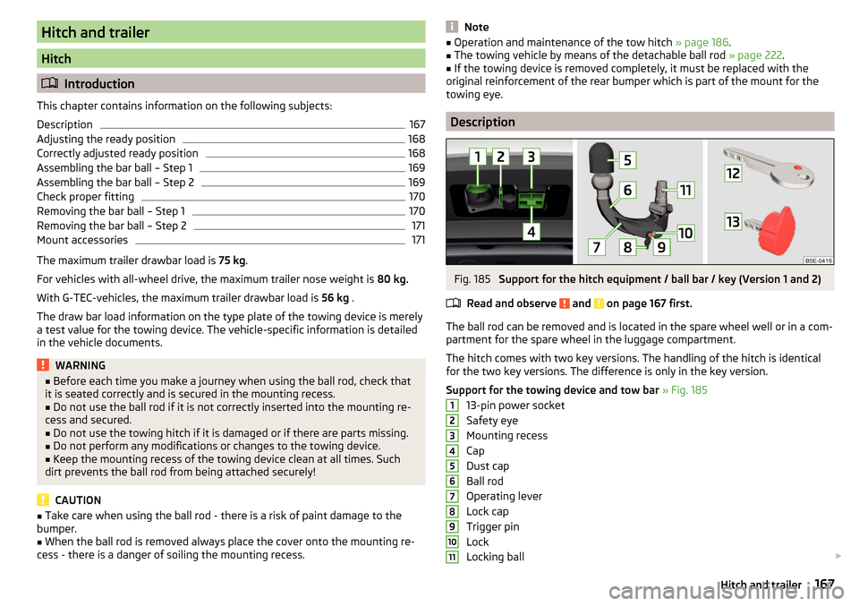
The ball rod can be removed and is located in the spare wheel well or in a com-
partment for the spare wheel in the luggage compartment.
The hitch comes with two key versions. The handling of the hitch is identical
for the two key versions. The difference is only in the key version.
Support for the towing device and tow bar » Fig. 185
13-pin power socket
Safety eye
Mounting recess
Cap
Dust cap
Ball rod
Operating lever
Lock cap
Trigger pin
Lock
Locking ball
1234567891011167Hitch and trailer
Page 232 of 268

No.Consumer8Lambda probe9Ignition, glow plug system, engine components10Fuel pump, ignition11Electrical auxiliary heating system12Electrical auxiliary heating system13Automatic gearbox14Windscreen heater - right15Horn16Ignition, fuel pump17ABS, ESC, motor control unit, relay coil for the heated windscreen18Databus, battery data module19Windscreen wipers20Alarm21Windscreen heater - left22Engine control unit23Starter24Electrical auxiliary heating system31Not assigned32Not assigned33Not assigned34Haldex clutch35Not assigned36Not assigned37Aux. heating38Not assigned
Bulbs
Introduction
This chapter contains information on the following subjects:
Bulb arrangement in the headlights
231
Replacing the low beam bulb
231Change bulb for long-distance, daytime running lights and parking light
switch232
Change bulb for additional parking light
232
Change bulb for fog light switch - Variant 1
232
Change bulb for fog light switch - Variant 2
233
Replacing the bulb for the licence plate light
233
Rear Light
234
Replacing bulbs in the rear light - Variant 1
235
Replacing bulbs in the rear light - Variant 2
235
Some manual skills are required to change a bulb. For this reason, we recom-
mend having bulbs replaced by a specialist garage or seeking other expert help
in the event of any uncertainties.
▶ Switch off the ignition and the relevant lights before replacing a bulb.
▶ Faulty bulbs must only be replaced with the same type of bulbs. The designa-
tion is located on the light socket or the glass bulb.
A stowage compartment for replacement bulbs is located in a plastic box in
the spare wheel or underneath the floor covering in the luggage compartment.
We recommend having the headlight settings checked by a specialist garage
after replacing a bulb in the low, high or fog beam.
In case of failure of a xenon gas discharge lamp or an LED diode, visit a special- ist garage.
WARNING■ Always read and observe the warnings before completing any work in the
engine compartment » page 194.■
Accidents can be caused if the road in front of the vehicle is not suffi-
ciently illuminated and the vehicle cannot or can only be seen with difficul-
ty by other road users.
■
Bulbs H7 H8 and H15 are pressurised and may burst when changing the
bulb - risk of injury! We therefore recommended wearing gloves and safety
glasses when changing a bulb.
■
Do not carry out any work on the Xenon gas discharge lamps - risk of
death!
CAUTION
Do not take hold of the glass bulb with naked fingers (even the smallest
amount of dirt reduces the working life of the light bulb). Use a clean cloth,
napkin, or similar. 230Do-it-yourself