sport mode SKODA OCTAVIA 2015 3.G / (5E) Owner's Manual
[x] Cancel search | Manufacturer: SKODA, Model Year: 2015, Model line: OCTAVIA, Model: SKODA OCTAVIA 2015 3.G / (5E)Pages: 268, PDF Size: 37.54 MB
Page 4 of 268
Table of Contents
On-board literature4
Notes
5
Structure and more information about the
Owner's Manual
6
Abbreviations
Safety
Passive Safety
8
General information
8
Correct and safe seated position
8
Seat belts
11
Using seat belts
11
Inertia reel and belt pretensioners
13
Airbag system
14
Description of the airbag system
14
Airbag overview
15
Deactivating airbags
19
Transporting children safely
20
Child seat
20
Fastening elements
23
Using the system
Cockpit
27
Overview
26
Instruments and warning lights
28
Instrument cluster
28
Warning lights
31
Information system
40
Driver information system
40
Driving data (Multifunction display)
41
MAXI DOT display
44Service interval display49SmartGate50
Unlocking and opening
53
Unlocking and locking
53
Anti-theft alarm system
58
Luggage compartment lid
59
Electric boot lid
60
Window operations
61
Panorama sliding/tilting roof
64
Lights and visibility
67
Lights
67
Interior lights
74
Visibility
76
Windscreen wipers and washers
77
Rear mirror
79
Seats and head restraints
81
Seats and head restraints
81
Seat features
85
Transporting and practical equipment
89
Useful equipment
89
Multimedia holder
99
Luggage compartment and transport of
cargo
100
Variable loading floor in the luggage
compartment (Estate)
107
Net partition
109
Roof rack
110
Heating and ventilation
112
Heating, manual air conditioning system,
Climatronic
112
Auxiliary heating (auxiliary heating and
ventilation)
117Driving
Starting-off and Driving120
Starting and stopping the engine using the
key
120
Starting and stopping the engine at the push
of the button
122
START-STOPsystem
124
Brakes and parking
126
Manual shifting of gears and pedals
128
Automatic gearbox
129
Running-in and economical driving
132
Avoiding damage to your vehicle
134
Assist systems
135
General information
135
Braking and stabilisation systems
135
OFF ROAD-mode
138
Parking aid (ParkPilot)
140
Rear View Camera
143
Park Assist
144
Cruise Control System
148
Adaptive Cruise Control (ACC)
150
Front Assist
155
Selection of the driving mode (Driving Mode
Selection)
157
Proactive passenger protection (Crew Protect
Assist)
160
Lane Departure Warning (Lane Assist)
160
Traffic sign recognition
162
Fatigue detection
164
Tyre pressure monitoring
165
Hitch and trailer
167
Hitch
167
Trailer
1722Table of Contents
Page 27 of 268
Attachment points of the systemFig. 20
Attachment points of the
-system
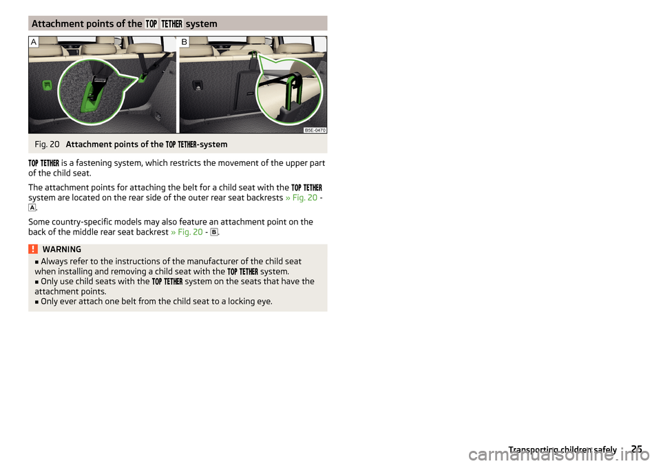
is a fastening system, which restricts the movement of the upper part
of the child seat.
The attachment points for attaching the belt for a child seat with the
system are located on the rear side of the outer rear seat backrests » Fig. 20 -
.
Some country-specific models may also feature an attachment point on the
back of the middle rear seat backrest » Fig. 20 -
.
WARNING■
Always refer to the instructions of the manufacturer of the child seat
when installing and removing a child seat with the system.■
Only use child seats with the
system on the seats that have the
attachment points.
■
Only ever attach one belt from the child seat to a locking eye.
25Transporting children safely
Page 105 of 268
Folding double hooksFig. 114
Folding double hooks
Read and observe and on page 101 first.
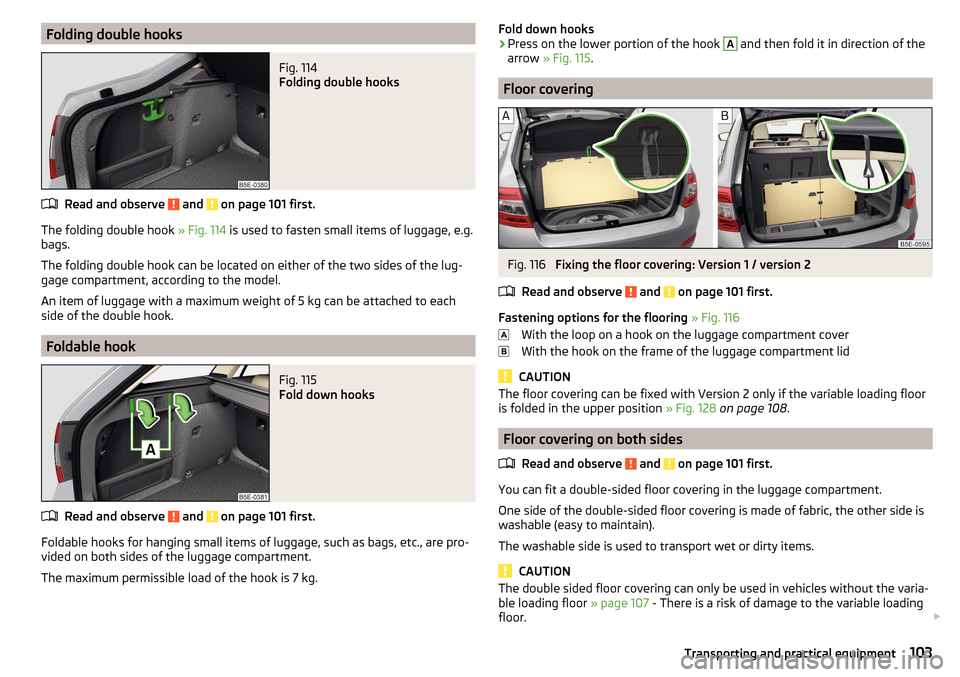
The folding double hook » Fig. 114 is used to fasten small items of luggage, e.g.
bags.
The folding double hook can be located on either of the two sides of the lug-
gage compartment, according to the model.
An item of luggage with a maximum weight of 5 kg can be attached to each
side of the double hook.
Foldable hook
Fig. 115
Fold down hooks
Read and observe and on page 101 first.
Foldable hooks for hanging small items of luggage, such as bags, etc., are pro- vided on both sides of the luggage compartment.
The maximum permissible load of the hook is 7 kg.
Fold down hooks›Press on the lower portion of the hook A and then fold it in direction of the
arrow » Fig. 115 .
Floor covering
Fig. 116
Fixing the floor covering: Version 1 / version 2
Read and observe
and on page 101 first.
Fastening options for the flooring » Fig. 116
With the loop on a hook on the luggage compartment cover
With the hook on the frame of the luggage compartment lid
CAUTION
The floor covering can be fixed with Version 2 only if the variable loading floor
is folded in the upper position » Fig. 128 on page 108 .
Floor covering on both sides
Read and observe
and on page 101 first.
You can fit a double-sided floor covering in the luggage compartment.
One side of the double-sided floor covering is made of fabric, the other side is
washable (easy to maintain).
The washable side is used to transport wet or dirty items.
CAUTION
The double sided floor covering can only be used in vehicles without the varia-
ble loading floor » page 107 - There is a risk of damage to the variable loading
floor. 103Transporting and practical equipment
Page 112 of 268
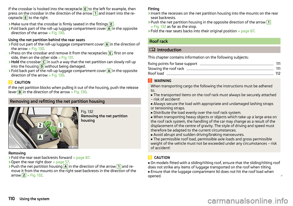
If the crossbar is hooked into the receptacle E to the left for example, then
press on the crossbar in the direction of the arrow 1 and insert into the re-
ceptacle E
to the right.
›
Make sure that the crossbar is firmly seated in the fittings
E
.
›
Fold back part of the roll-up luggage compartment cover
A
in the opposite
direction of the arrow » Fig. 130.
Using the net partition behind the rear seats
›
Fold out part of the roll-up luggage compartment cover
A
in the direction of
the arrow » Fig. 130.
›
Press on the crossbar and remove it from the receptacles
E
, first on one
side, then on the other side » Fig. 131.
›
Hold the crossbar
C
in such a way that the net partition can slowly roll up
into the housing
D
without being damaged.
›
Fold back part of the roll-up luggage compartment cover
A
in the opposite
direction of the arrow » Fig. 130.
CAUTION
If the net partition blocks when pulling it out of the housing, push the release
lever B in the direction of the arrow » Fig. 130.
Removing and refitting the net partition housing
Fig. 132
Removing the net partition
housing
Removing
›
Fold the rear seat backrests forward » page 87.
›
Open the rear right door » page 57.
›
Push the net partition housing
A
in the direction of the arrow
1
and re-
move it from the mounts on the right seat backrests in the direction of the
arrow
2
» Fig. 132 .
Fitting›Insert the recesses on the net partition housing into the mounts on the rear
seat backrests.›
Push the net partition housing in the opposite direction of the arrow
1
» Fig. 132 as far as the stop.
›
Fold the rear seats backs into their original position » page 87.
Roof rack
Introduction
This chapter contains information on the following subjects:
fixing points for base support
111
Stowing the roof rack
111
Roof load
112WARNINGWhen transporting cargo the following the instructions must be adhered
to.■
The transported items on the roof rack must always be securely attached
– risk of accident!
■
Always secure the load with appropriate and undamaged lashing straps
or tensioning straps.
■
Distribute the load evenly over the roof rack system.
■
When transporting heavy objects or objects which take up a large area on
the roof rack system, the handling of the car may change as a result of the
displacement of the centre of gravity. The style of driving and speed must
therefore be adapted to the current circumstances.
■
Avoid abrupt and sudden driving/braking manoeuvres.
■
The permissible roof load, permissible axle loads and gross permissible
weight of the vehicle must not be exceeded under any circumstances – risk
of accident!
CAUTION
■ On models fitted with a sliding/tilting roof, ensure that the sliding/tilting roof
does not strike any items of luggage transported on the roof when tilting.■
Ensure that the luggage compartment lid does not hit the roof load when
opened.
110Using the system
Page 128 of 268
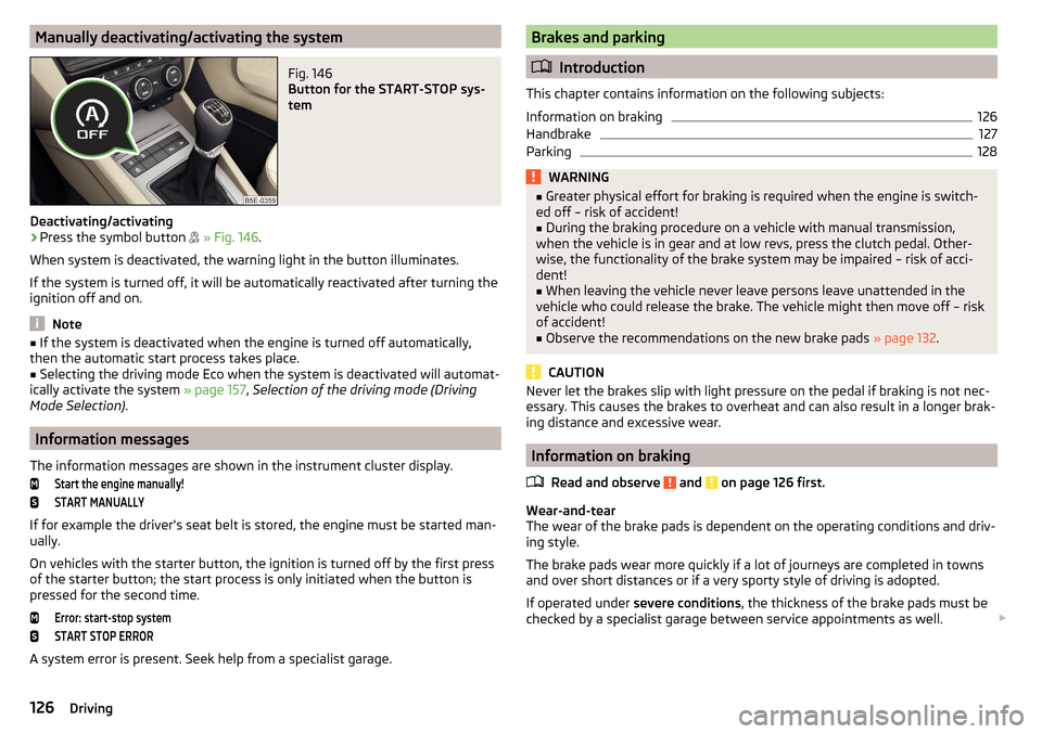
Manually deactivating/activating the systemFig. 146
Button for the START-STOP sys-
tem
Deactivating/activating
›
Press the symbol button
» Fig. 146 .
When system is deactivated, the warning light in the button illuminates.
If the system is turned off, it will be automatically reactivated after turning the
ignition off and on.
Note
■ If the system is deactivated when the engine is turned off automatically,
then the automatic start process takes place.■
Selecting the driving mode Eco when the system is deactivated will automat-
ically activate the system » page 157, Selection of the driving mode (Driving
Mode Selection) .
Information messages
The information messages are shown in the instrument cluster display.
Start the engine manually!START MANUALLY
If for example the driver's seat belt is stored, the engine must be started man-
ually.
On vehicles with the starter button, the ignition is turned off by the first press
of the starter button; the start process is only initiated when the button is
pressed for the second time.
Error: start-stop systemSTART STOP ERROR
A system error is present. Seek help from a specialist garage.
Brakes and parking
Introduction
This chapter contains information on the following subjects:
Information on braking
126
Handbrake
127
Parking
128WARNING■ Greater physical effort for braking is required when the engine is switch-
ed off – risk of accident!■
During the braking procedure on a vehicle with manual transmission,
when the vehicle is in gear and at low revs, press the clutch pedal. Other-
wise, the functionality of the brake system may be impaired – risk of acci-
dent!
■
When leaving the vehicle never leave persons leave unattended in the
vehicle who could release the brake. The vehicle might then move off – risk of accident!
■
Observe the recommendations on the new brake pads » page 132.
CAUTION
Never let the brakes slip with light pressure on the pedal if braking is not nec-
essary. This causes the brakes to overheat and can also result in a longer brak-
ing distance and excessive wear.
Information on braking
Read and observe
and on page 126 first.
Wear-and-tear
The wear of the brake pads is dependent on the operating conditions and driv-
ing style.
The brake pads wear more quickly if a lot of journeys are completed in towns
and over short distances or if a very sporty style of driving is adopted.
If operated under severe conditions , the thickness of the brake pads must be
checked by a specialist garage between service appointments as well.
126Driving
Page 132 of 268
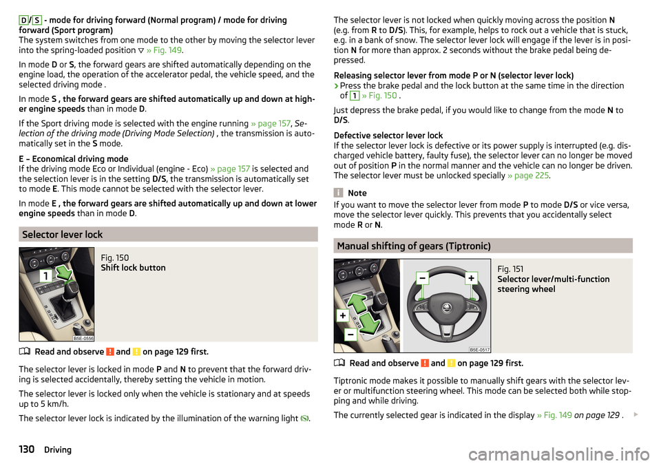
D/S - mode for driving forward (Normal program) / mode for driving
forward (Sport program)
The system switches from one mode to the other by moving the selector lever
into the spring-loaded position
» Fig. 149 .
In mode D or S, the forward gears are shifted automatically depending on the
engine load, the operation of the accelerator pedal, the vehicle speed, and the
selected driving mode .
In mode S , the forward gears are shifted automatically up and down at high-
er engine speeds than in mode D.
If the Sport driving mode is selected with the engine running » page 157, Se-
lection of the driving mode (Driving Mode Selection) , the transmission is auto-
matically set in the S mode.
E – Economical driving mode
If the driving mode Eco or Individual (engine - Eco) » page 157 is selected and
the selection lever is in the setting D/S, the transmission is automatically set
to mode E. This mode cannot be selected with the selector lever.
In mode E , the forward gears are shifted automatically up and down at lower
engine speeds than in mode D.
Selector lever lock
Fig. 150
Shift lock button
Read and observe and on page 129 first.
The selector lever is locked in mode P and N to prevent that the forward driv-
ing is selected accidentally, thereby setting the vehicle in motion.
The selector lever is locked only when the vehicle is stationary and at speeds
up to 5 km/h.
The selector lever lock is indicated by the illumination of the warning light .
The selector lever is not locked when quickly moving across the position
N
(e.g. from R to D/S ). This, for example, helps to rock out a vehicle that is stuck,
e.g. in a bank of snow. The selector lever lock will engage if the lever is in posi-
tion N for more than approx. 2 seconds without the brake pedal being de-
pressed.
Releasing selector lever from mode P or N (selector lever lock)›
Press the brake pedal and the lock button at the same time in the direction
of
1
» Fig. 150 .
Just depress the brake pedal, if you would like to change from the mode N to
D/S .
Defective selector lever lock
If the selector lever lock is defective or its power supply is interrupted (e.g. dis-
charged vehicle battery, faulty fuse), the selector lever can no longer be moved
out of position P in the normal manner and the vehicle can no longer be driven.
The selector lever must be unlocked specially » page 225.
Note
If you want to move the selector lever from mode P to mode D/S or vice versa,
move the selector lever quickly. This prevents that you accidentally select
mode R or N.
Manual shifting of gears (Tiptronic)
Fig. 151
Selector lever/multi-function
steering wheel
Read and observe and on page 129 first.
Tiptronic mode makes it possible to manually shift gears with the selector lev-
er or multifunction steering wheel. This mode can be selected both while stop-
ping and while driving.
The currently selected gear is indicated in the display » Fig. 149 on page 129 .
130Driving
Page 159 of 268
The system should only be disabled in exceptional cases » .
The system can be activated or deactivated in one of two ways. ▶ In the instrument cluster display » page 48, Menu itemAssist systems
.
▶ Infotainment » Owner´s Manual Infotainment , chapter CAR - vehicle set-
tings .
The following functions can be activated or deactivated separately in infotain-
ment. ▶ Distance warning
▶ Advance warning
f the distance-warning function was deactivated before switching off the igni-
tion, it remains deactivated after switching on the ignition.
WARNINGIn the following situations, Front Assist should be switched off for safety
reasons.■
When the vehicle is being towed away.
■
When the vehicle is on a rolling test bench.
■
If an unfounded warning was issued or a system action carried out.
■
When on a truck, car ferry or similar.
Information messages
Read and observe
and on page 155 first.
The information messages are shown in the instrument cluster display.
Front Assist: no sensor view.
The sensor is soiled or covered.
Stop the vehicle, switch off the engine and clean the sensor or remove the ob-
stacle causing the lack of visibility » page 135, Radar sensor .
If after engine start the message persists, then the help of a professional or-
ganisation is required.
Front Assist not available.
The system is not available for an unknown reason.
Stop the vehicle, switch off the engine and then start it again.
If after engine start the message persists, then the help of a professional or- ganisation is required.
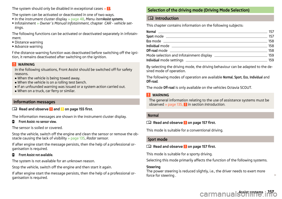
Selection of the driving mode (Driving Mode Selection)
Introduction
This chapter contains information on the following subjects:
Normal157Sport
mode
157Eco
mode
158Individual
mode
158Off-road
mode
158
Mode selection and Infotainment display
159Individual
mode settings
159
By selecting the driving mode, the driving behaviour can be adapted to the de-
sired mode of operation.
The following modes of operation are available
Normal
,
Sport
,
Eco
,
Individual
and
Off-road
.
The mode
Off-road
is only available on the vehicles Octavia SCOUT.
WARNINGThe general information relating to the use of assistance systems must be
observed » page 135, in section Introduction .
Normal
Read and observe on page 157 first.
This mode is suitable for a conventional driving.
Sport
mode
Read and observe
on page 157 first.
This mode is suitable for a sporty driving.
Selecting this mode primarily affects the function of the following systems.
Steering
The power steering is reduced slightly, i.e., the driver needs to exert more
force for steering .
157Assist systems
Page 161 of 268
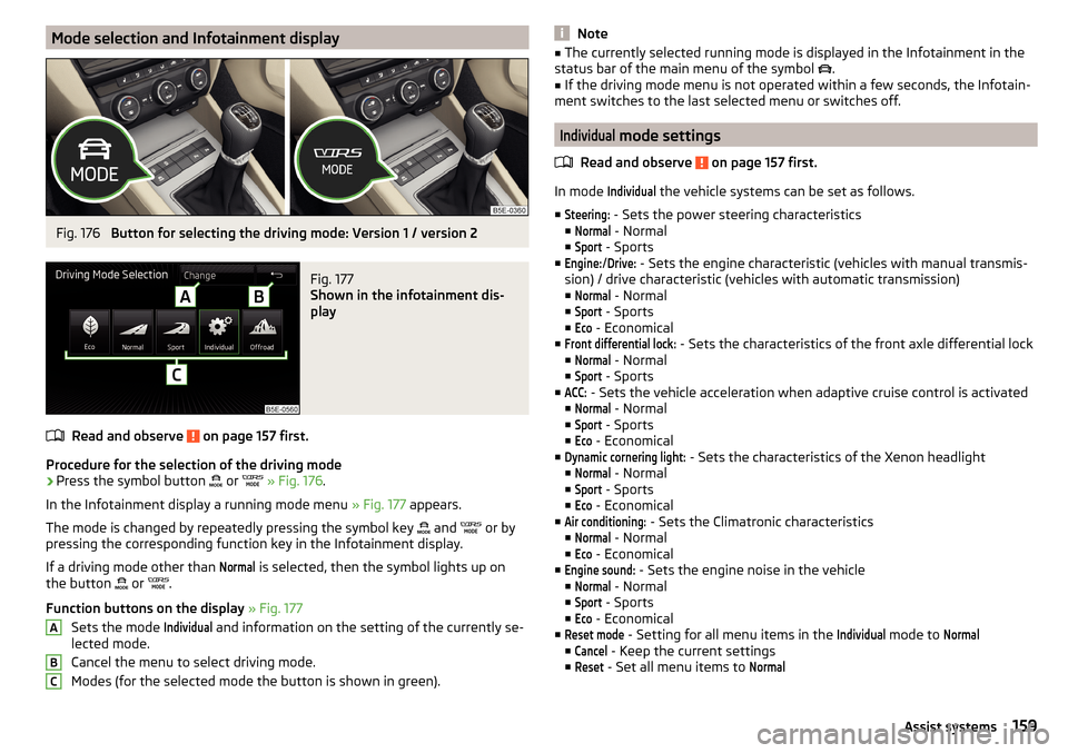
Mode selection and Infotainment displayFig. 176
Button for selecting the driving mode: Version 1 / version 2
Fig. 177
Shown in the infotainment dis-
play
Read and observe on page 157 first.
Procedure for the selection of the driving mode
›
Press the symbol button or
» Fig. 176 .
In the Infotainment display a running mode menu » Fig. 177 appears.
The mode is changed by repeatedly pressing the symbol key and
or by
pressing the corresponding function key in the Infotainment display.
If a driving mode other than
Normal
is selected, then the symbol lights up on
the button or
.
Function buttons on the display » Fig. 177
Sets the mode
Individual
and information on the setting of the currently se-
lected mode.
Cancel the menu to select driving mode.
Modes (for the selected mode the button is shown in green).
ABCNote■ The currently selected running mode is displayed in the Infotainment in the
status bar of the main menu of the symbol .■
If the driving mode menu is not operated within a few seconds, the Infotain-
ment switches to the last selected menu or switches off.
Individual
mode settings
Read and observe
on page 157 first.
In mode
Individual
the vehicle systems can be set as follows.
■
Steering:
- Sets the power steering characteristics
■
Normal
- Normal
■
Sport
- Sports
■
Engine:
/
Drive:
- Sets the engine characteristic (vehicles with manual transmis-
sion) / drive characteristic (vehicles with automatic transmission)
■
Normal
- Normal
■
Sport
- Sports
■
Eco
- Economical
■
Front differential lock:
- Sets the characteristics of the front axle differential lock
■
Normal
- Normal
■
Sport
- Sports
■
ACC:
- Sets the vehicle acceleration when adaptive cruise control is activated
■
Normal
- Normal
■
Sport
- Sports
■
Eco
- Economical
■
Dynamic cornering light:
- Sets the characteristics of the Xenon headlight
■
Normal
- Normal
■
Sport
- Sports
■
Eco
- Economical
■
Air conditioning:
- Sets the Climatronic characteristics
■
Normal
- Normal
■
Eco
- Economical
■
Engine sound:
- Sets the engine noise in the vehicle
■
Normal
- Normal
■
Sport
- Sports
■
Eco
- Economical
■
Reset mode
- Setting for all menu items in the
Individual
mode to
Normal
■
Cancel
- Keep the current settings
■
Reset
- Set all menu items to
Normal159Assist systems
Page 162 of 268

Proactive passenger protection (Crew Protect Assist)
Introduction
This chapter contains information on the following subjects:
Function
160
Proactive passenger protection (hereafter known as system) increases pas-
senger protection in the front seats in situations that could lead to vehicle im-
pact or overturning.
WARNINGThe general information relating to the use of assistance systems must be
observed » page 135, in section Introduction .
Note
The system component service life is monitored electronically. Further infor-
mation » page 35 , Safety systems .
Function
Read and observe
on page 160 first.
In critical driving situations (e.g. during emergency braking or a sudden changein direction), the following steps can be taken separately or combined in order
to reduce the risk of serious injury.
▶ The front passenger's and driver's seatbelts, if worn, are automatically ten-
sioned closely over the body.
▶ The windows in the side doors (if open) are automatically closed up to a gap
of about 5 cm from the edge.
▶ The sliding/tilting roof is closed.
Once the critical driving situation has passed, the tension on the seatbelts will
be released again.
The system operates at two levels of protection.
The first level of protection
The system already intervenes in situations that may occur during dynamic
driving. As a result, this primarily helps to keep the driver and the passenger in
the correct seated position.
The first protection level can be deactivated in one of the following ways.
▶ The system deactivation in the Infotainment » Owner´s Manual Infotain-
ment , chapter CAR - vehicle settings .
▶ Deactivation of TCS » page 136.
▶ Selecting the driving mode Sport
» page 157 .
Provided that the driving mode
Sport
is not selected, the system is activated
over the two levels of protection after switching the ignition off and on again.
The second level of protection
The system intervenes only if the situation is evaluated as critical, such as in
panic braking at high speeds.
This level of protection cannot be deactivated.
Note
If the front passenger front airbag is deactivated » page 19 the belt tensioning
function for the front passenger seat is switched off.
Lane Departure Warning (Lane Assist)
Introduction
Fig. 178
Camera viewing window for Lane
Assist
This chapter contains information on the following subjects:
Operation
161
Activation / deactivation
162
Information messages
162
The lane departure warning (hereinafter known as system) helps to keep the
vehicle between the boundary lines of a lane.
The system detects the boundary lines of a lane using the camera » Fig. 178.
160Driving
Page 254 of 268
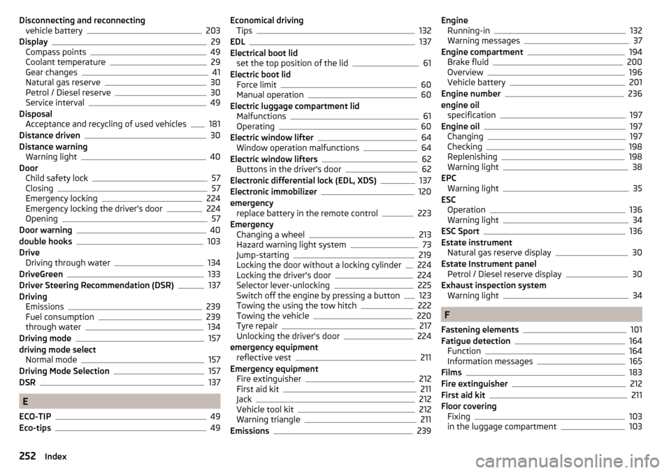
Disconnecting and reconnectingvehicle battery203
Display29
Compass points49
Coolant temperature29
Gear changes41
Natural gas reserve30
Petrol / Diesel reserve30
Service interval49
Disposal Acceptance and recycling of used vehicles
181
Distance driven30
Distance warning Warning light
40
Door Child safety lock
57
Closing57
Emergency locking224
Emergency locking the driver's door224
Opening57
Door warning40
double hooks103
Drive Driving through water
134
DriveGreen133
Driver Steering Recommendation (DSR)137
Driving Emissions
239
Fuel consumption239
through water134
Driving mode157
driving mode select Normal mode
157
Driving Mode Selection157
DSR137
E
ECO-TIP
49
Eco-tips49
Economical driving Tips132
EDL137
Electrical boot lid set the top position of the lid
61
Electric boot lid Force limit
60
Manual operation60
Electric luggage compartment lid Malfunctions
61
Operating60
Electric window lifter64
Window operation malfunctions64
Electric window lifters62
Buttons in the driver's door62
Electronic differential lock (EDL, XDS)137
Electronic immobilizer120
emergency replace battery in the remote control
223
Emergency Changing a wheel
213
Hazard warning light system73
Jump-starting219
Locking the door without a locking cylinder224
Locking the driver's door224
Selector lever-unlocking225
Switch off the engine by pressing a button123
Towing the using the tow hitch222
Towing the vehicle220
Tyre repair217
Unlocking the driver's door224
emergency equipment reflective vest
211
Emergency equipment Fire extinguisher
212
First aid kit211
Jack212
Vehicle tool kit212
Warning triangle211
Emissions239
Engine Running-in132
Warning messages37
Engine compartment194
Brake fluid200
Overview196
Vehicle battery201
Engine number236
engine oil specification
197
Engine oil197
Changing197
Checking198
Replenishing198
Warning light38
EPC Warning light
35
ESC Operation
136
Warning light34
ESC Sport136
Estate instrument Natural gas reserve display
30
Estate Instrument panel Petrol / Diesel reserve display
30
Exhaust inspection system Warning light
34
F
Fastening elements
101
Fatigue detection164
Function164
Information messages165
Films183
Fire extinguisher212
First aid kit211
Floor covering Fixing
103
in the luggage compartment103
252Index