instrument cluster SKODA OCTAVIA 2016 3.G / (5E) Owner's Guide
[x] Cancel search | Manufacturer: SKODA, Model Year: 2016, Model line: OCTAVIA, Model: SKODA OCTAVIA 2016 3.G / (5E)Pages: 324, PDF Size: 48.85 MB
Page 122 of 324
▶You are recommended to speak louder at higher speeds, so that the sound of
your voice is not drowned out by the increased ambient noise.
▶ During voice control, limit additional noise in the vehicle, e.g. passengers
talking at the same time.WARNINGThe emergency number should be dialled manually. Your voice commands
may not be recognised in such situations. The telephone connection may
not be established or the connection may take too much time to complete.
CAUTION
■ The messages are generated by Infotainment. Flawless clarity (e.g. road or
city name) cannot always be guaranteed.■
For some Infotainment languages, there is no voice control available. Info-
tainment indicates this fact through a text message that is displayed on the
screen after setting the Infotainment language.
Note
During voice control, no nav. announcements and traffic announcements are
played.
Voice control on / off
Fig. 151
Voice control: Main menu
Activating
›
Press the button on infotainment
or press the button
on the multi-
function steering wheel.
the main menu is displayed » Fig. 151.
Switching off
›
Press the button on infotainment twice
or press the button twice
on
the multifunction steering wheel.
› or
Issue the voice command “ End voice control”.
Operation principle
Fig. 152
Example of screen display
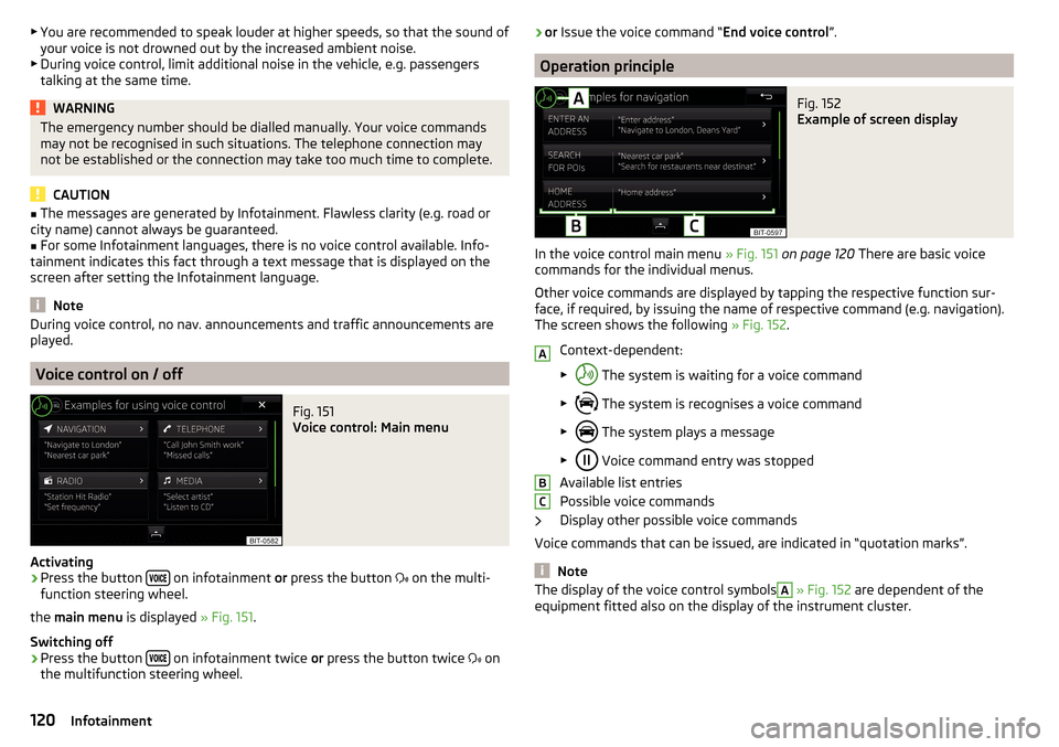
In the voice control main menu » Fig. 151 on page 120 There are basic voice
commands for the individual menus.
Other voice commands are displayed by tapping the respective function sur-
face, if required, by issuing the name of respective command (e.g. navigation).
The screen shows the following » Fig. 152.
Context-dependent:
▶ The system is waiting for a voice command
▶ The system is recognises a voice command
▶ The system plays a message
▶ Voice command entry was stopped
Available list entries
Possible voice commands
Display other possible voice commands
Voice commands that can be issued, are indicated in “quotation marks”.
Note
The display of the voice control symbolsA » Fig. 152 are dependent of the
equipment fitted also on the display of the instrument cluster.ABC120Infotainment
Page 181 of 324
For trailer towing , We recommend that you activate recognition of road signs
relevant to trailers.›
Press the button, then tap on the function surface
→
Driver assistance
→
Show road signs relevant to trailers
.
Route guidance
Introduction to the subject
A route is created by starting route guidance to a destination. Additional inter-
mediate destinations can be added to the route.
The route guidance takes place as follows
▶ Through graphical driving instructions on the Infotainment screen and in the
display of the instrument cluster.
▶ With nav. announcements.
Infotainment tries to allow for continued guidance even if the navigation data
is incomplete or there is no data at all for the given area.
The route is recalculated each time if you ignore driving recommendations or change the route.
CAUTION
The nav. announcements provided may vary from the actual situations, e.g.
due to out-of-date navigation data.
Destination details
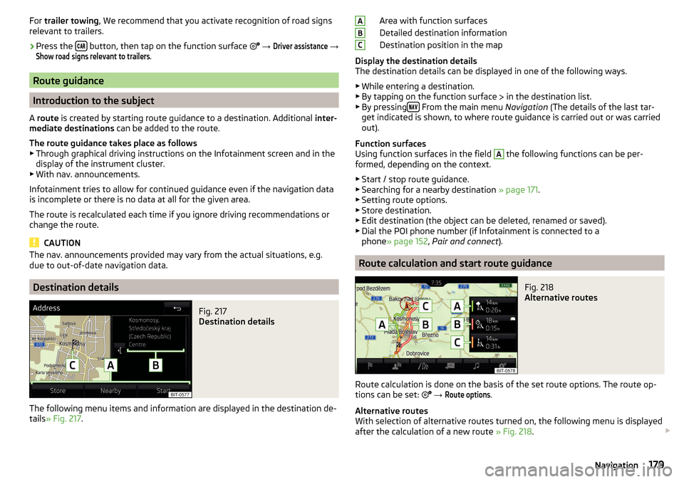
Fig. 217
Destination details
The following menu items and information are displayed in the destination de-
tails » Fig. 217 .
Area with function surfaces
Detailed destination information
Destination position in the map
Display the destination details
The destination details can be displayed in one of the following ways.
▶ While entering a destination.
▶ By tapping on the function surface
in the destination list.
▶ By pressing
From the main menu
Navigation (The details of the last tar-
get indicated is shown, to where route guidance is carried out or was carried
out).
Function surfaces
Using function surfaces in the field
A
the following functions can be per-
formed, depending on the context.
▶ Start / stop route guidance.
▶ Searching for a nearby destination » page 171.
▶ Setting route options.
▶ Store destination.
▶ Edit destination (the object can be deleted, renamed or saved).
▶ Dial the POI phone number (if Infotainment is connected to a
phone » page 152 , Pair and connect ).
Route calculation and start route guidance
Fig. 218
Alternative routes
Route calculation is done on the basis of the set route options. The route op-
tions can be set:
→
Route options
.
Alternative routes
With selection of alternative routes turned on, the following menu is displayed
after the calculation of a new route » Fig. 218.
ABC179Navigation
Page 182 of 324
Calculate the most economical route with shortest travelling time and
distance travelled – the route is highlighted green
Calculate the fastest route to the destination, even if a detour is nec-
essary - the route is highlighted in red
Calculate the shortest route to the destination, even if a longer travel-
ling time is required - the route is highlighted in orange
In the function surfaces of the alternative routes, information on the route
length and the estimated travel time and the following symbols are displayed
(applies to Infotainment Columbus).
Use of a toll motorway
Use of a train / ferry
Using a toll tunnel
Use of a toll road
Using a vignette duty highway
It is possible to select an already calculated alternative route before the calcu- lation of the remaining routes is completed.
Selecting the type of route will start route guidance.
If no route selection is made within 30 s after the calculation of all routes, the
route guidance is automatically started according to the preferred route type.
Route calculation for the trailer
When driving with a trailer or any other accessory connected to the trailer
socket, we recommend that you switch on the trailer recognition, if necessary
to set the maximum speed for towing a trailer.
›
For calculating the route for towing a trailer, tap the function surface in the
main navigation menu
→
Route options
→
.
Demo mode
The Demo mode provides a travel simulation to the entered destination. The
function offers the option to travel through the calculated route “virtually”.
When the Demo mode is turned on, a menu for route guidance in the Demo
mode or in normal operation is displayed before the start of route guidance.
›
To switch on/off in the main menu Navigation, tap on the function surface
Tap →
Advanced settings
→
Demo mode
.
When the DemoMode is switched on, the route starting point can be defined.
ABC› In the
Navigation main menu, tap on the function surface Tap → Advancedsettings
→
Define demo mode starting point
.›
Define the starting point by entering the address or the current vehicle posi-
tion.
›
The demo mode starting point can also be set as long as the demo mode is
turned on by tap the desired map location and the menu item
Start Demo Mode
is selected » page 176, Tap map point .
Graphical driving recommendations
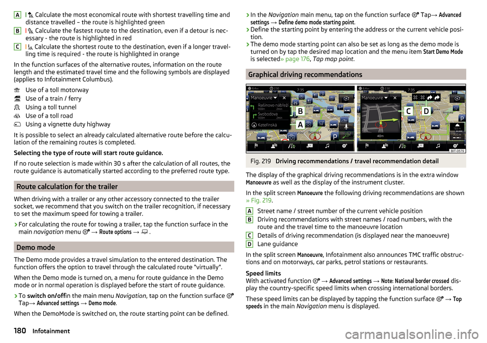
Fig. 219
Driving recommendations / travel recommendation detail
The display of the graphical driving recommendations is in the extra window
Manoeuvre
as well as the display of the instrument cluster.
In the split screen
Manoeuvre
the following driving recommendations are shown
» Fig. 219 .
Street name / street number of the current vehicle position
Driving recommendations with street names / road numbers, with the
route and the travel time to the manoeuvre location
Details of driving recommendation (is displayed near the manoeuvre)
Lane guidance
In the split screen
Manoeuvre
, Infotainment also announces TMC traffic obstruc-
tions and on motorways, car parks, petrol stations or restaurants.
Speed limits
With activated function
→
Advanced settings
→
Note: National border crossed
dis-
play the country-specific speed limits when crossing international borders.
These speed limits can be displayed by tapping the function surface
→
Topspeeds
in the main Navigation menu is displayed.
ABCD180Infotainment
Page 192 of 324
Note■The engine running noises may be louder at first for a short time after start-
ing the cold engine.■
You should not switch on any major electrical components during the heat-
ing period, otherwise the vehicle battery will be drained unnecessarily.
■
After switching off the ignition, the radiator fan may (also intermittently)
continue to operate for approx. 10 minutes.
Problems with the engine start - vehicles with starter button
Fig. 230
Starting the engine - press the
button with the key
Read and observe and on page 188 first.
If no engine start is possible and the display of the instrument cluster shows a
message that the key could not be detected by the system or there is a system
fault, then try to start the engine as follows.
›
Press the starter button with the key » Fig. 230.
If the engine does not start, the help of a specialist garage is required.
CAUTION
The key may not be detected by the system if the battery in the key is running
out of charge or the signal fails (strong electromagnetic field) or is shielded
(e.g. in an aluminium case).
START-STOPsystem
Introduction
This chapter contains information on the following subjects:
Operation
190
manually activate/deactivate system
191The START STOP system (hereinafter referred to as the system) reduces CO 2
emissions and harmful emissions, and saves fuel.
If the system determine that the engine is not needed when the vehicle stops
or is at a standstill (e.g. at the traffic lights), it turns off the engine and starts it
again when moving off.
The system function depends on many factors. Some of them are down to the
driver, the others are systemic and can neither be influenced nor identified.
Therefore the system may react differently in situations which seem identi-
cal from the driver's perspective.
The system is automatically activated every time the ignition is switched on
(even where this has previously been manually deactivated with the button ).
Note
If the engine has stopped due to the system, the ignition remains on.
Operation
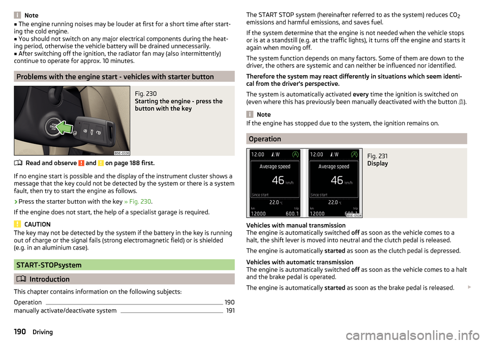
Fig. 231
Display
Vehicles with manual transmission
The engine is automatically switched off as soon as the vehicle comes to a
halt, the shift lever is moved into neutral and the clutch pedal is released.
The engine is automatically started as soon as the clutch pedal is depressed.
Vehicles with automatic transmission
The engine is automatically switched off as soon as the vehicle comes to a halt
and the brake pedal is operated.
The engine is automatically started as soon as the brake pedal is released.
190Driving
Page 193 of 324
Conditions for the system function
The following conditions must be met for the system to function correctly.
The driver's door is closed.
The driver has fastened the seat belt.
The driving speed was higher than 4 km.h after the last stop.
System status
The system status is shown in the display when the vehicle comes to a halt
» Fig. 231 .
The engine is automatically switched off; when the vehicle moves off, the
ignition process will be automatically initiated.
The engine is not automatically switched off.
The engine does not shut down when the vehicle stops, if e.g. the following
applies.
▶ The engine temperature for the proper function of the system has not yet
been reached.
▶ The charge state of the vehicle battery is too low.
▶ The current consumption is too high.
▶ High air conditioning or heating output (high fan speed, big difference be-
tween the desired and actual interior temperature).
If the engine has shut down automatically but the system detects that the en- gine is required to run (e.g. if the brake pedal is pressed repeatedly) then the
system automatically starts up the engine.
More information about the current system status can be displayed in infotain-
ment screen, in the
→
→
Veh. status
menu.
If there is a system fault , the following message will appear in the display of
the instrument cluster. Seek help from a specialist garage.
Note
■ If the driver's seat belt is removed for more than 30 seconds or the driver's
door is opened after the engine has switched off automatically, the engine will
have to be restarted manually.■
No automatic engine shut-down takes place when a vehicle with automatic
transmission is moving at low speed (e.g. during a traffic jam) and remains sta-
tionary after pressing the brake pedal lightly. Automatic engine shut-down
takes place if you press the brake pedal down with more force.
■
For vehicles with automatic transmission there is no automatic engine shut-
down when the system detects a manoeuvring action due to a large steering
angle.
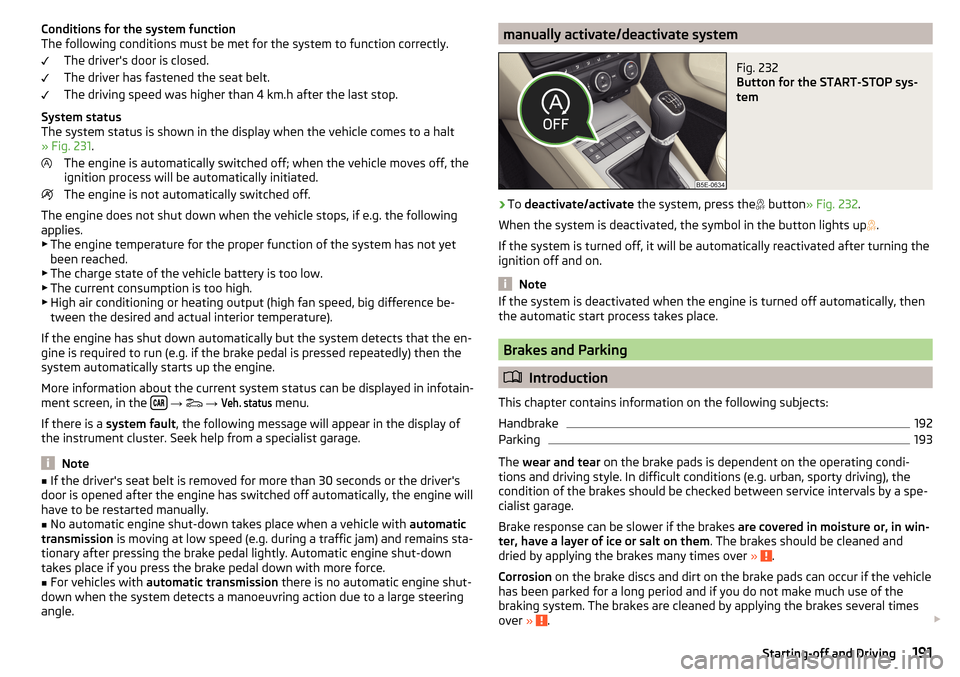
manually activate/deactivate systemFig. 232
Button for the START-STOP sys-
tem
›
To deactivate/activate the system, press the
button
» Fig. 232 .
When the system is deactivated, the symbol in the button lights up .
If the system is turned off, it will be automatically reactivated after turning the
ignition off and on.
Note
If the system is deactivated when the engine is turned off automatically, then
the automatic start process takes place.
Brakes and Parking
Introduction
This chapter contains information on the following subjects:
Handbrake
192
Parking
193
The wear and tear on the brake pads is dependent on the operating condi-
tions and driving style. In difficult conditions (e.g. urban, sporty driving), the
condition of the brakes should be checked between service intervals by a spe-
cialist garage.
Brake response can be slower if the brakes are covered in moisture or, in win-
ter, have a layer of ice or salt on them . The brakes should be cleaned and
dried by applying the brakes many times over »
.
Corrosion on the brake discs and dirt on the brake pads can occur if the vehicle
has been parked for a long period and if you do not make much use of the
braking system. The brakes are cleaned by applying the brakes several times
over »
.
191Starting-off and Driving
Page 194 of 324
Before negotiating a long or steep gradient , reduce speed and shift down a
gear. As a result, the braking effect of the engine will be used, reducing the
load on the brakes. If, nevertheless, there is a need for additional braking, it
should be carried out at intervals.
Emergency braking warning - If it is necessary to brake hard, the system may
cause the brake lights to automatically flash, to alert the traffic behind.
New brake pads must first be““run in”” because these do not initially have the
best possible braking effect. Drive especially carefully for the first 200 km or
so.
If the brake fluid level is too low, it can cause faults in the braking system ;
the warning light will light up in the instrument cluster » page 33
,
Braking
system . If the warning light does not light up, yet the stopping distance is per-
ceived to be longer than before, the driving style should be adapted in view of
the unknown cause of the problem, and braking kept to a minimum - seek the
help of a specialist garage without delay.
The brake booster increases the pressure generated with the brake pedal. The
brake booster only operates when the engine is running.WARNING■ Greater physical effort for braking is required when the engine is switch-
ed off – risk of accident!■
During the braking procedure on a vehicle with manual transmission,
when the vehicle is in gear and at low revs, press the clutch pedal. Other-
wise, the functionality of the brake system may be impaired – risk of acci-
dent!
■
Do not depress the brake pedal, if there is no requirement to slow down.
This causes the brakes to overheat and can also result in a longer braking
distance and excessive wear - There is a risk of an accident!
■
Only brake for the purpose of drying and cleaning the brake discs if the
traffic conditions permit this. Do not place any other road users in jeopardy.
■
Recommendations for new brake pads should be followed.
■
When stopping and parking, the parking brake should always be applied
firmly, otherwise the vehicle could move off - There is a risk of an accident!
■
If a front spoiler, full wheel trim, etc. is mounted retrospectively, it must
be ensured that the air supply to the front wheel brakes is not reduced.
Otherwise, the front brakes could be in danger of overheating – There is a
risk of an accident!
HandbrakeFig. 233
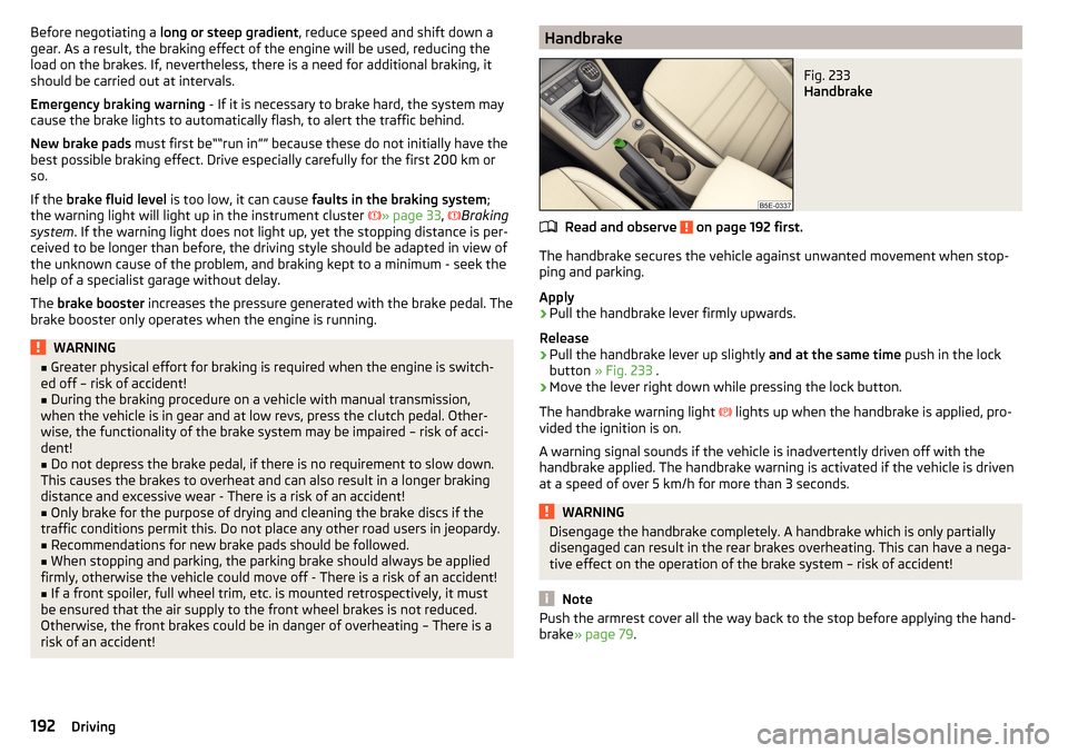
Handbrake
Read and observe on page 192 first.
The handbrake secures the vehicle against unwanted movement when stop- ping and parking.
Apply
›
Pull the handbrake lever firmly upwards.
Release
›
Pull the handbrake lever up slightly and at the same time push in the lock
button » Fig. 233 .
›
Move the lever right down while pressing the lock button.
The handbrake warning light lights up when the handbrake is applied, pro-
vided the ignition is on.
A warning signal sounds if the vehicle is inadvertently driven off with the
handbrake applied. The handbrake warning is activated if the vehicle is driven
at a speed of over 5 km/h for more than 3 seconds.
WARNINGDisengage the handbrake completely. A handbrake which is only partially
disengaged can result in the rear brakes overheating. This can have a nega-
tive effect on the operation of the brake system – risk of accident!
Note
Push the armrest cover all the way back to the stop before applying the hand-
brake » page 79 .192Driving
Page 200 of 324
NoteResetting the single-trip memory “since start” also resets the average con-
sumption E, the driving assessment D, and the diagram C.
Radiator shutters
The radiator shutters located in front of the radiator (hereinafter: shutter) help
to reduce CO 2 emissions as well as harmful emissions and to save fuel.
If the system detects that it is possible to reduce the amount of air flowing to
the radiator, it closes the blinds. As a result, the air resistance of the vehicle is
reduced.
If, due to a function impairment of the shutters, a driving speed of 150 km/h is
reached, an appropriate message is shown in the display of the instrument
cluster.
After the display of the above message, the top speed of the vehicle is auto-
matically limited to around 160 km/h.
If this message appears in the winter, the cause may be ice or snow caught up
in the blinds. After the ice or snow has thawed, the blinds are functional again.
If the impairment not due to ice or snow, then assistance from a specialist
should be sought.
Avoiding damage to your vehicle
Introduction
This chapter contains information on the following subjects:
Driving Tips
198
Driving through water
198
Driving Tips
Only drive on roads and terrain that correspond to the vehicle parame-
ters » page 288 , Technical data .
The driver is always responsible for deciding whether the vehicle can cope
with the conditions and the terrain.
WARNING■ Adjust the speed and driving style to the current visibility, weather, road
and traffic conditions. Too high a speed or an erroneous manoeuvre may
cause serious injury and damage to the vehicle.■
Combustible objects such as dry leaves or twigs caught under the base of
the vehicle could ignite on hot vehicle parts - risk of fire!
CAUTION
■ Pay attention to the ground clearance of the vehicle! When driving over ob-
jects which are larger than the ground clearance, the vehicle can get damaged.■
Any objects that get trapped under the vehicle floor must be removed as
soon as possible. These items can cause damage to the vehicle (e.g. to parts of
the fuel or brake system).
Driving through water
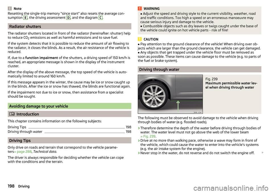
Fig. 239
Maximum permissible water lev-
el when driving through water
The following must be observed to avoid damage to the vehicle when driving
through bodies of water (e.g. flooded roads).
›
Therefore determine the depth of the water before driving through bodies of
water. The water level must not go above the web of the lower beam
» Fig. 239 .
›
Drive at no more than walking pace, otherwise a wave may form in front of
the vehicle, which could cause the water to enter into the vehicle’s systems
(e.g. the air intake system for the engine).
›
Never stop in the water, do not reverse and do not switch the engine off.
198Driving
Page 202 of 324
The sensor is a component of the ACC » page 214 and Front Assist
» page 219 systems.
The sensor function may be impaired in the events of one of the following. ▶ The sensor cover is soiled (e.g. with mud, snow etc.).
▶ The area in front of and around the sensor cover is obscured (e.g. by labels,
auxiliary headlights etc.).
▶ When visibility is poor, (e.g. fog, heavy rain, thick snowfall).
If the sensor is covered or dirty, the corresponding message appears in the in-
strument cluster display for the ACC system » page 218, Malfunctions or Front
Assist system » page 221, Malfunctions .WARNING■
If you suspect that the sensor is damaged, deactivate the ACC system and
Front Assist system » page 216» page 220 . Have the sensor checked by a
specialist garage.■
A collision or damage in the front or lower area of the vehicle could affect
the sensor function - there is risk of accident! Have the sensor checked by
a specialist garage.
■
Do not cover the area in front of and around the sensor cover. This can
lead to impaired function of the sensor - risk of accidents!
CAUTION
Remove the snow with a brush and the ice with a solvent-free de-icer.
Braking and stabilisation systems
Introduction
This chapter contains information on the following subjects:
Stability Control (ESC)
200
ESC Sport
200
Anti-lock braking system (ABS)
201
Engine drag torque control (MSR)
201
Traction control (TCS)
201
Electronic Differential Lock (EDL and XDS)
201
Active steering assist (DSR)
202
Brake Assist (HBA)
202
Hill Start Assist (HHC)
202Multicollision brake (MCB)202Trailer stabilisation system (TSA)202
The brake and stabilization systems are automatically activated each time the
ignition is switched on, unless otherwise indicated.
The error display is in Chapter » page 32, Warning lights .
WARNINGThe general information relating to the use of assistance systems must be
observed » page 199, in section Introduction .
Stability Control (ESC)
Read and observe
on page 200 first.
ESC improves vehicle stability in critical driving situations (e.g. if the vehicle
starts to skid) by the braking the individual wheels to maintain the direction.
If there is a TCS intervention, the indicator light flashes in the instrument
cluster.
ESC Sport
Read and observe
on page 200 first.
ESC Sport allows for a sportier driving style. With ESC Sport activated, no ESC
intervention takes place when the vehicle slightly oversteers and understeers,
and ASR is so limited that the drive wheels can be spun.
Activation
›
Press and hold down the
» Fig. 241 on page 201 button.
›
or: On Infotainment, press the button
→ Press the function area
→
ESC system:
→
ESC Sport
.
With activation the warning light
lights up in the instrument cluster and an
appropriate message is displayed in the instrument cluster.
Deactivation
›
Press the
» Fig. 241 on page 201 button.
›
or: On Infotainment, press the button
→ Press the function area
→
ESC system:
→
Activated
.
With deactivation the warning light extinguishes in the instrument cluster
and an appropriate message is displayed in the instrument cluster.
200Driving
Page 203 of 324
Anti-lock braking system (ABS)Read and observe
on page 200 first.
ABS prevents the wheels locking when braking. Thus helping the driver to
maintain control of the vehicle.
The intervention of the ABS is noticeable from the pulsating movements of
the brake pedal which is accompanied by noises.
When the ABS system is active, do not brake periodically or reduce the pres-
sure on the brake pedal.
Engine drag torque control (MSR)
Read and observe
on page 200 first.
MSR counteracts the tendency of the drive wheels to lock during downshifts
or sudden deceleration (e.g. on icy or an otherwise slippery road surface).
If the drive wheels should lock, then the engine speed is automatically in-
creased. This reduces the braking effect of the engine and the wheels can ro-
tate freely again.
Traction control (TCS)
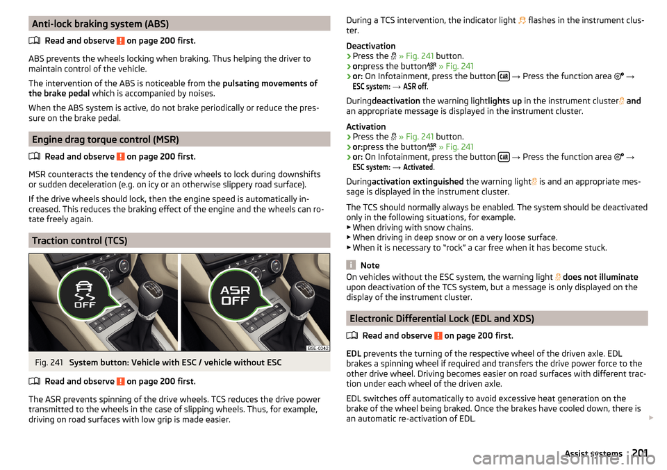
Fig. 241
System button: Vehicle with ESC / vehicle without ESC
Read and observe
on page 200 first.
The ASR prevents spinning of the drive wheels. TCS reduces the drive power transmitted to the wheels in the case of slipping wheels. Thus, for example,
driving on road surfaces with low grip is made easier.
During a TCS intervention, the indicator light flashes in the instrument clus-
ter.
Deactivation›
Press the
» Fig. 241 button.
›
or:press the button
» Fig. 241
›
or: On Infotainment, press the button
→ Press the function area
→
ESC system:
→
ASR off
.
During deactivation the warning light lights up in the instrument cluster
and
an appropriate message is displayed in the instrument cluster.
Activation
›
Press the
» Fig. 241 button.
›
or:press the button
» Fig. 241
›
or: On Infotainment, press the button
→ Press the function area
→
ESC system:
→
Activated
.
During activation extinguished the warning light
is and an appropriate mes-
sage is displayed in the instrument cluster.
The TCS should normally always be enabled. The system should be deactivated
only in the following situations, for example. ▶ When driving with snow chains.
▶ When driving in deep snow or on a very loose surface.
▶ When it is necessary to “rock” a car free when it has become stuck.
Note
On vehicles without the ESC system, the warning light does not illuminate
upon deactivation of the TCS system, but a message is only displayed on the
display of the instrument cluster.
Electronic Differential Lock (EDL and XDS)
Read and observe
on page 200 first.
EDL prevents the turning of the respective wheel of the driven axle. EDL
brakes a spinning wheel if required and transfers the drive power force to the
other drive wheel. Driving becomes easier on road surfaces with different trac-
tion under each wheel of the driven axle.
EDL switches off automatically to avoid excessive heat generation on the
brake of the wheel being braked. Once the brakes have cooled down, there is
an automatic re-activation of EDL.
201Assist systems
Page 205 of 324
OFF ROADmode
Introduction
This chapter contains information on the following subjects:
Operation
203
Hill Descent Assistant
203
ESC OFF ROAD
204
ASR OFF ROAD
204
EDS OFF ROAD
204
ABS OFF ROAD
204
The OFF ROAD mode includes functions that help to overcome routes that are
difficult to navigate when travelling on non-paved roads.
But even with OFF ROAD mode activated, your vehicle is never a true SUV.
WARNINGThe general information relating to the use of assistance systems must be
observed » page 199, in section Introduction .
CAUTION
■
The OFF ROAD mode is not designed for the use on common roads.■All four wheels must be fitted with the same tyres approved by ŠKODA AUTO
to ensure the OFF ROAD mode operates correctly.
Operation
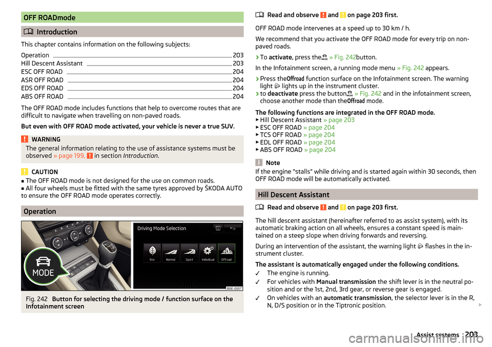
Fig. 242
Button for selecting the driving mode / function surface on the
Infotainment screen
Read and observe and on page 203 first.
OFF ROAD mode intervenes at a speed up to 30 km / h.
We recommend that you activate the OFF ROAD mode for every trip on non-
paved roads.
›
To activate , press the
» Fig. 242 button.
In the Infotainment screen, a running mode menu » Fig. 242 appears.
›
Press the
Offroad
function surface on the Infotainment screen. The warning
light
lights up in the instrument cluster.
›
to deactivate press the button
» Fig. 242 and in the infotainment screen,
choose another mode than the
Offroad
mode.
The following functions are integrated in the OFF ROAD mode.
▶ Hill Descent Assistant » page 203
▶ ESC OFF ROAD » page 204
▶ TCS OFF ROAD » page 204
▶ EDL OFF ROAD » page 204
▶ ABS OFF ROAD » page 204
Note
If the engine “stalls” while driving and is started again within 30 seconds, then
OFF ROAD mode will be automatically activated.
Hill Descent Assistant
Read and observe
and on page 203 first.
The hill descent assistant (hereinafter referred to as assist system), with itsautomatic braking action on all wheels, ensures a constant speed is main-
tained on a steep slope when driving forwards and reversing.
During an intervention of the assistant, the warning light flashes in the in-
strument cluster.
The assistant is automatically engaged under the following conditions. The engine is running.
For vehicles with Manual transmission the shift lever is in the neutral po-
sition and or the 1st, 2nd, 3rd gear, or reverse gear is engaged.
On vehicles with an automatic transmission , the selector lever is in the R,
N, D/S position or in the Tiptronic position.
203Assist systems