tow SKODA OCTAVIA 2016 3.G / (5E) Owner's Guide
[x] Cancel search | Manufacturer: SKODA, Model Year: 2016, Model line: OCTAVIA, Model: SKODA OCTAVIA 2016 3.G / (5E)Pages: 324, PDF Size: 48.85 MB
Page 105 of 324
›On the other side, press on the crossbar in the direction of the arrow and
hook it into the appropriate receptacle D.›
Make sure that the crossbar is firmly seated in the two mountings
D
.
›
Fold back part
A
of the roll-up luggage compartment cover in the opposite
direction of the arrow » Fig. 123.
Using the net partition behind the rear seats
›
Fold out part
A
of the roll-up luggage compartment cover in the direction of
arrow » Fig. 123 .
›
Press on the crossbar and remove it from the receptacles
D
» Fig. 124 , first
on one side, then on the other side.
›
The crossbar
C
Hold in such a way that the net partition can slowly roll up
without being damaged.
›
Fold back part
A
of the roll-up luggage compartment cover in the opposite
direction of the arrow » Fig. 123.
Pull out and secure the net partition behind the front seats
The process is analogous to that for behind the rear seats. Before pulling out
the net partition, the rear seat backs are to be folded forwards. After rolling up
the net partition into the housing, the rear seat backs are folded back
» page 79 .
CAUTION
If the net partition blocks when pulling it out, push the release lever B in the
direction of the arrow » Fig. 123.
Removing and installing the net partition housing
Fig. 125
Removing the net partition
housing
›
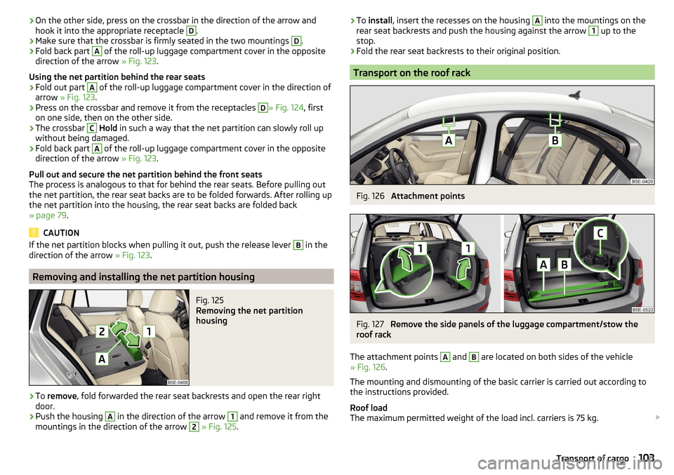
To remove , fold forwarded the rear seat backrests and open the rear right
door.
›
Push the housing
A
in the direction of the arrow
1
and remove it from the
mountings in the direction of the arrow
2
» Fig. 125 .
›To
install , insert the recesses on the housing A into the mountings on the
rear seat backrests and push the housing against the arrow 1 up to the
stop.›
Fold the rear seat backrests to their original position.
Transport on the roof rack
Fig. 126
Attachment points
Fig. 127
Remove the side panels of the luggage compartment/stow the
roof rack
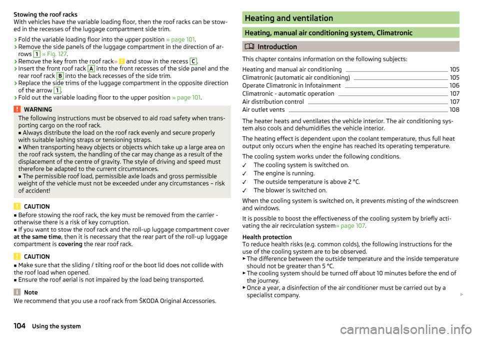
The attachment points
A
and
B
are located on both sides of the vehicle
» Fig. 126 .
The mounting and dismounting of the basic carrier is carried out according to
the instructions provided.
Roof load
The maximum permitted weight of the load incl. carriers is 75 kg.
103Transport of cargo
Page 106 of 324
Stowing the roof racks
With vehicles have the variable loading floor, then the roof racks can be stow-
ed in the recesses of the luggage compartment side trim.›
Fold the variable loading floor into the upper position » page 101.
›
Remove the side panels of the luggage compartment in the direction of ar-
rows
1
» Fig. 127 .
›
Remove the key from the roof rack » and stow in the recess
C
.
›
Insert the front roof rack
A
into the front recesses of the side panel and the
rear roof rack
B
into the back recesses of the side trim.
›
Replace the side trims of the luggage compartment in the opposite direction
of the arrow
1
.
›
Fold out the variable loading floor to the upper position » page 101.
WARNINGThe following instructions must be observed to aid road safety when trans-
porting cargo on the roof rack.■
Always distribute the load on the roof rack evenly and secure properly
with suitable lashing straps or tensioning straps.
■
When transporting heavy objects or objects which take up a large area on
the roof rack system, the handling of the car may change as a result of the
displacement of the centre of gravity. The style of driving and speed must
therefore be adapted to the current circumstances.
■
The permissible roof load, permissible axle loads and gross permissible
weight of the vehicle must not be exceeded under any circumstances – risk
of accident!
CAUTION
■ Before stowing the roof rack, the key must be removed from the carrier -
otherwise there is a risk of key corruption.■
If you want to stow the roof rack and the roll-up luggage compartment cover
at the same time , then it is necessary that the rear part of the roll-up luggage
compartment is covering the rear roof rack.
CAUTION
■
Make sure that the sliding / tilting roof or the boot lid does not collide with
the roof load when opened.■
Ensure the roof aerial is not impaired by the load being transported.
Note
We recommend that you use a roof rack from ŠKODA Original Accessories.Heating and ventilation
Heating, manual air conditioning system, Climatronic
Introduction
This chapter contains information on the following subjects:
Heating and manual air conditioning
105
Climatronic (automatic air conditioning)
105
Operate Climatronic in Infotainment
106
Climatronic - automatic operation
107
Air distribution control
107
Air outlet vents
108
The heater heats and ventilates the vehicle interior. The air conditioning sys-
tem also cools and dehumidifies the vehicle interior.
The heating effect is dependent upon the coolant temperature, thus full heat
output only occurs when the engine has reached its operating temperature.
The cooling system works under the following conditions. The cooling system is switched on.
The engine is running.
The outside temperature is above 2 °C.
The blower is switched on.
When the cooling system is switched on, it prevents misting of the windscreen
and windows.
It is possible to boost the effectiveness of the cooling system by briefly acti-
vating the air recirculation system » page 107.
Health protection
To reduce health risks (e.g. common colds), the following instructions for the
use of the cooling system are to be observed. ▶ The difference between the outside temperature and the inside temperature
should not be greater than 5 °C.
▶ The cooling system should be turned off about 10 minutes before the end of
the journey.
▶ Once a year, a disinfection of the air conditioner must be carried out by a
specialist company.
104Using the system
Page 125 of 324
■Touchscreen tone - Switch on/off audible tone when touching the screen
■No navigation sound during call
- Switching on / off the nav. announcements dur-
ing a telephone call (not applicable to Infotainment Bolero)
Display settings
›
Press the button, then tap on the function surface
Tap →
Screen
.
■
Switch off screen (in 10 seconds)
- Enable / disable the automatic power off func-
tion
■
Brightness:
- Adjusts the brightness of the screen
■
Touchscreen tone
- Switch on/off audible tone when touching the screen
■
Animation when finger near screen
- Turn the proximity sensors on/off (When the
function is on, e.g. Navigation will be shown in the main menu when moving a
finger towards the bottom bar with the function surfaces on the screen)
■
Show clock in standby mode
- Time and date displayed on the screen when the
ignition is switched on and Infotainment is switched off
Time and date settings
›
Press the button, then tap on the function surface
→
Time and date
.
■
Clock time source:
- Setting the time source: Manual / GPS (applies to Infotain-
ment Columbus, Amundsen)
■
Time:
- Time settings
■
Summer time
- Switches the summer time setting on/off (applies to Infotain-
ment Columbus, Amundsen)
■
Automatic summertime
- Turn on / off the automatic switch to daylight saving
time
■
Time zone:
- Choice of time zone
■
Time format:
- Specify the time format
■
Date:
- Date settings
■
Date format:
- Setting the date format
Setting the Infotainment language
›
Press the button, then tap on the function surface
→
Language
.
›
Select the Infotainment language.
In some languages, after selecting the function surface
Female
and
Male
are dis-
played for the choice of voice prompts for Infotainment.
Note■ When a language is selected which does not support voice control, Infotain-
ment will indicate this with a message on the screen.■
The messages are generated by Infotainment. Flawless clarity (e.g. road or
city name) cannot always be guaranteed.
Additional keypad language settings
›
Press the button, then tap on the function surface
→
Additional keypadlanguages
.
In this menu, a keyboard language set can be added to allow the entering of
characters other than those in the currently selected language (function sur-
face ).
Unit settings
›
Press the button, then tap on the function surface
→
Units
.
■
Distance:
- Distance units
■
Speed:
- Speed units
■
Temperature:
- Temperature units
■
Volume:
- Volume units
■
Consumption:
- Consumption units
■
CNG consump.:
- CNG consumption units
■
Pressure:
- Pressure units for tire pressure
Setting data transfer
An active data transfer allows data transfer between Infotainment and the ex-
ternal device (e.g. MirrorLink ®
application) or the operation of some Infotain-
ment functions using the application of the external device (e.g. ŠKODA Media
Command).
›
Press the button, then tap on the function surface
→
Mobile device datatransfer
.
■
Activate data transfer for ŠKODA apps
- Turning data transfer on and off
■
Use apps to operate::
- Setting Infotainment operation via the applications of the
external device (applies to Infotainment Columbus)
■
Deactivate
- Deactivation of Infotainment operation via an external device
■
Confirm
- Infotainment operation with required confirmation
■
Allow
- Infotainment operation without required confirmation
123Infotainment settings - Columbus, Amundsen, Bolero
Page 179 of 324
Switching on / off of the split screen display » page 171
Switching on/ off of the selected POI categories display » page 176, Tap
map point
If the map scale of the 2D Map or 3D Map is greater than 10 km (5 miles), then
the map is automatically displayed as 2D and aligned in the direction of north.
If the scale is increased beyond this value, then the map is switched back to
the original representation.
Map scale
Fig. 213
Function surfaces for the map
scale change
It is possible to change the map scale manually or to turn on the automatic
change of scale.
Symbols of the scale function surfaces
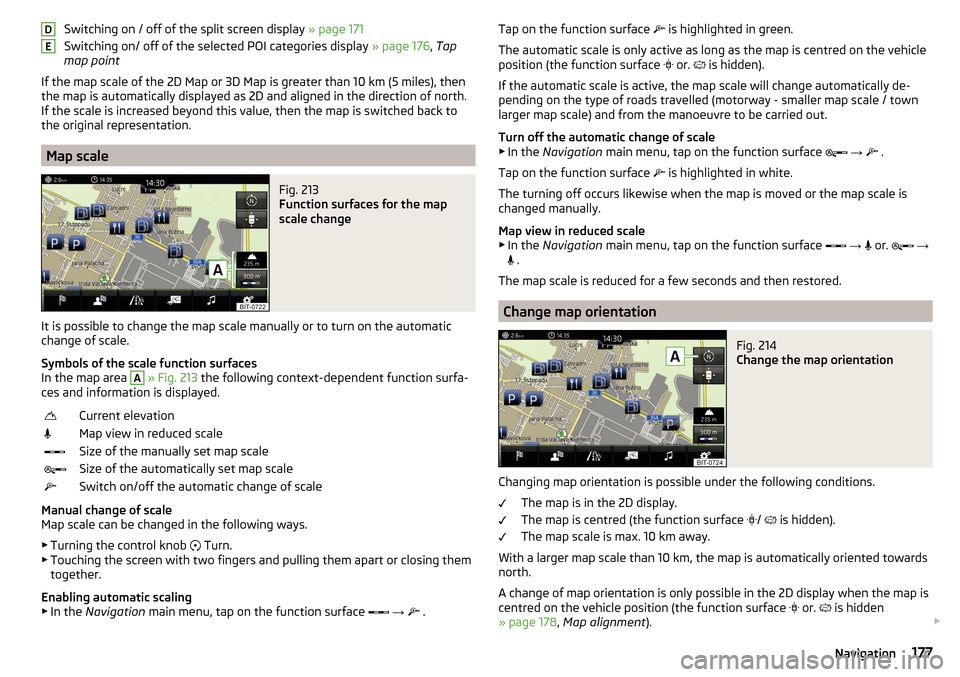
In the map area
A
» Fig. 213 the following context-dependent function surfa-
ces and information is displayed.
Current elevationMap view in reduced scaleSize of the manually set map scaleSize of the automatically set map scaleSwitch on/off the automatic change of scale
Manual change of scale
Map scale can be changed in the following ways.
▶ Turning the control knob Turn.
▶ Touching the screen with two fingers and pulling them apart or closing them
together.
Enabling automatic scaling
▶ In the Navigation main menu, tap on the function surface
→
.
DETap on the function surface
is highlighted in green.
The automatic scale is only active as long as the map is centred on the vehicle position (the function surface
or. is hidden).
If the automatic scale is active, the map scale will change automatically de-
pending on the type of roads travelled (motorway - smaller map scale / town larger map scale) and from the manoeuvre to be carried out.
Turn off the automatic change of scale
▶ In the Navigation main menu, tap on the function surface
→
.
Tap on the function surface
is highlighted in white.
The turning off occurs likewise when the map is moved or the map scale is
changed manually.
Map view in reduced scale ▶ In the Navigation main menu, tap on the function surface
→
or.
→
.
The map scale is reduced for a few seconds and then restored.
Change map orientation
Fig. 214
Change the map orientation
Changing map orientation is possible under the following conditions. The map is in the 2D display.
The map is centred (the function surface /
is hidden).
The map scale is max. 10 km away.
With a larger map scale than 10 km, the map is automatically oriented towards
north.
A change of map orientation is only possible in the 2D display when the map is
centred on the vehicle position (the function surface or.
is hidden
» page 178 , Map alignment ).
177Navigation
Page 180 of 324
With a larger map scale than 10 km, the map is automatically oriented towards
north.›
to Change the map orientation From the main menu navigation the function
surface 1)
A
» Fig. 214 .
The map is oriented to the north
The symbol
the vehicle position rotates, the map and the Polar Star Symbol
1)
do not rotate.
Map oriented to the direction of travel
The map and the Polar Star Symbol 1)
rotate, the symbol
The vehicle posi-
tion does not rotate.
Map alignment
Fig. 215
Map centring
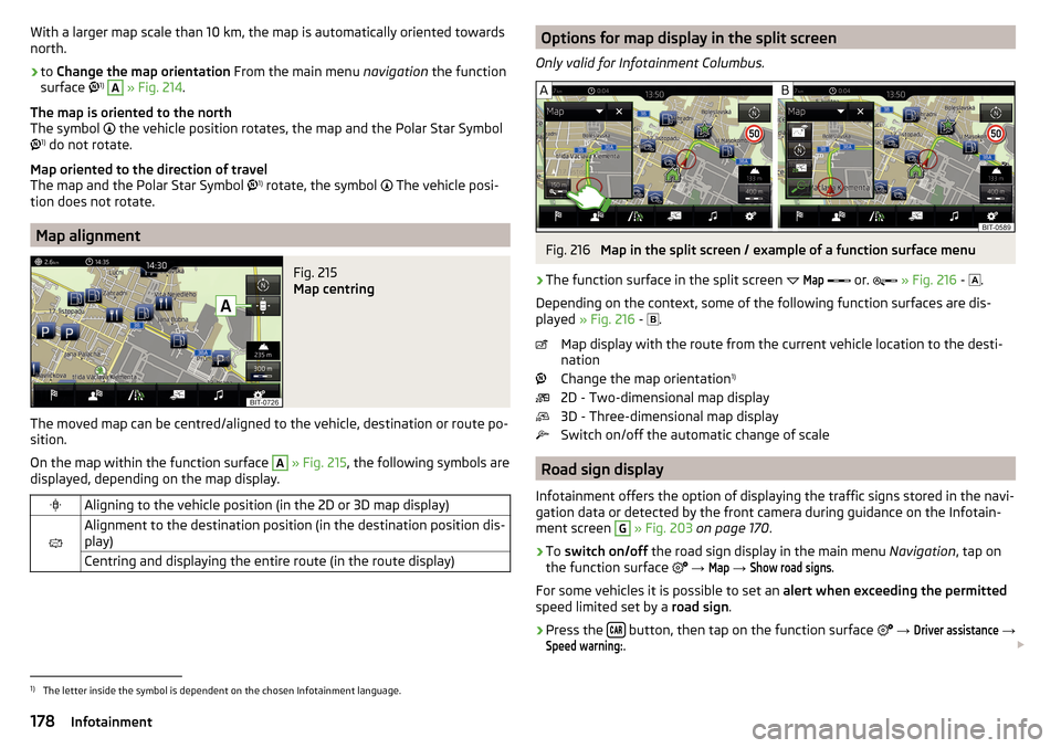
The moved map can be centred/aligned to the vehicle, destination or route po-
sition.
On the map within the function surface
A
» Fig. 215 , the following symbols are
displayed, depending on the map display.
Aligning to the vehicle position (in the 2D or 3D map display)
Alignment to the destination position (in the destination position dis-
play)Centring and displaying the entire route (in the route display)Options for map display in the split screen
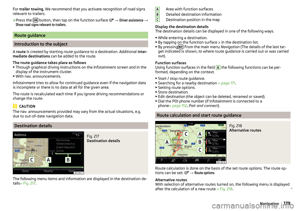
Only valid for Infotainment Columbus.Fig. 216
Map in the split screen / example of a function surface menu
›
The function surface in the split screen
Map
or.
» Fig. 216 -
.
Depending on the context, some of the following function surfaces are dis-
played » Fig. 216 -
.
Map display with the route from the current vehicle location to the desti-
nation
Change the map orientation 1)
2D - Two-dimensional map display
3D - Three-dimensional map display
Switch on/off the automatic change of scale
Road sign display
Infotainment offers the option of displaying the traffic signs stored in the navi-
gation data or detected by the front camera during guidance on the Infotain-
ment screen
G
» Fig. 203 on page 170 .
›
To switch on/off the road sign display in the main menu Navigation, tap on
the function surface
→
Map
→
Show road signs
.
For some vehicles it is possible to set an alert when exceeding the permitted
speed limited set by a road sign.
›
Press the button, then tap on the function surface
→
Driver assistance
→
Speed warning:
.
1)
The letter inside the symbol is dependent on the chosen Infotainment language.
178Infotainment
Page 181 of 324
For trailer towing , We recommend that you activate recognition of road signs
relevant to trailers.›
Press the button, then tap on the function surface
→
Driver assistance
→
Show road signs relevant to trailers
.
Route guidance
Introduction to the subject
A route is created by starting route guidance to a destination. Additional inter-
mediate destinations can be added to the route.
The route guidance takes place as follows
▶ Through graphical driving instructions on the Infotainment screen and in the
display of the instrument cluster.
▶ With nav. announcements.
Infotainment tries to allow for continued guidance even if the navigation data
is incomplete or there is no data at all for the given area.
The route is recalculated each time if you ignore driving recommendations or change the route.
CAUTION
The nav. announcements provided may vary from the actual situations, e.g.
due to out-of-date navigation data.
Destination details
Fig. 217
Destination details
The following menu items and information are displayed in the destination de-
tails » Fig. 217 .
Area with function surfaces
Detailed destination information
Destination position in the map
Display the destination details
The destination details can be displayed in one of the following ways.
▶ While entering a destination.
▶ By tapping on the function surface
in the destination list.
▶ By pressing
From the main menu
Navigation (The details of the last tar-
get indicated is shown, to where route guidance is carried out or was carried
out).
Function surfaces
Using function surfaces in the field
A
the following functions can be per-
formed, depending on the context.
▶ Start / stop route guidance.
▶ Searching for a nearby destination » page 171.
▶ Setting route options.
▶ Store destination.
▶ Edit destination (the object can be deleted, renamed or saved).
▶ Dial the POI phone number (if Infotainment is connected to a
phone » page 152 , Pair and connect ).
Route calculation and start route guidance
Fig. 218
Alternative routes
Route calculation is done on the basis of the set route options. The route op-
tions can be set:
→
Route options
.
Alternative routes
With selection of alternative routes turned on, the following menu is displayed
after the calculation of a new route » Fig. 218.
ABC179Navigation
Page 182 of 324
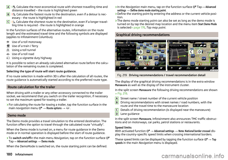
Calculate the most economical route with shortest travelling time and
distance travelled – the route is highlighted green
Calculate the fastest route to the destination, even if a detour is nec-
essary - the route is highlighted in red
Calculate the shortest route to the destination, even if a longer travel-
ling time is required - the route is highlighted in orange
In the function surfaces of the alternative routes, information on the route
length and the estimated travel time and the following symbols are displayed
(applies to Infotainment Columbus).
Use of a toll motorway
Use of a train / ferry
Using a toll tunnel
Use of a toll road
Using a vignette duty highway
It is possible to select an already calculated alternative route before the calcu- lation of the remaining routes is completed.
Selecting the type of route will start route guidance.
If no route selection is made within 30 s after the calculation of all routes, the
route guidance is automatically started according to the preferred route type.
Route calculation for the trailer
When driving with a trailer or any other accessory connected to the trailer
socket, we recommend that you switch on the trailer recognition, if necessary
to set the maximum speed for towing a trailer.
›
For calculating the route for towing a trailer, tap the function surface in the
main navigation menu
→
Route options
→
.
Demo mode
The Demo mode provides a travel simulation to the entered destination. The
function offers the option to travel through the calculated route “virtually”.
When the Demo mode is turned on, a menu for route guidance in the Demo
mode or in normal operation is displayed before the start of route guidance.
›
To switch on/off in the main menu Navigation, tap on the function surface
Tap →
Advanced settings
→
Demo mode
.
When the DemoMode is switched on, the route starting point can be defined.
ABC› In the
Navigation main menu, tap on the function surface Tap → Advancedsettings
→
Define demo mode starting point
.›
Define the starting point by entering the address or the current vehicle posi-
tion.
›
The demo mode starting point can also be set as long as the demo mode is
turned on by tap the desired map location and the menu item
Start Demo Mode
is selected » page 176, Tap map point .
Graphical driving recommendations
Fig. 219
Driving recommendations / travel recommendation detail
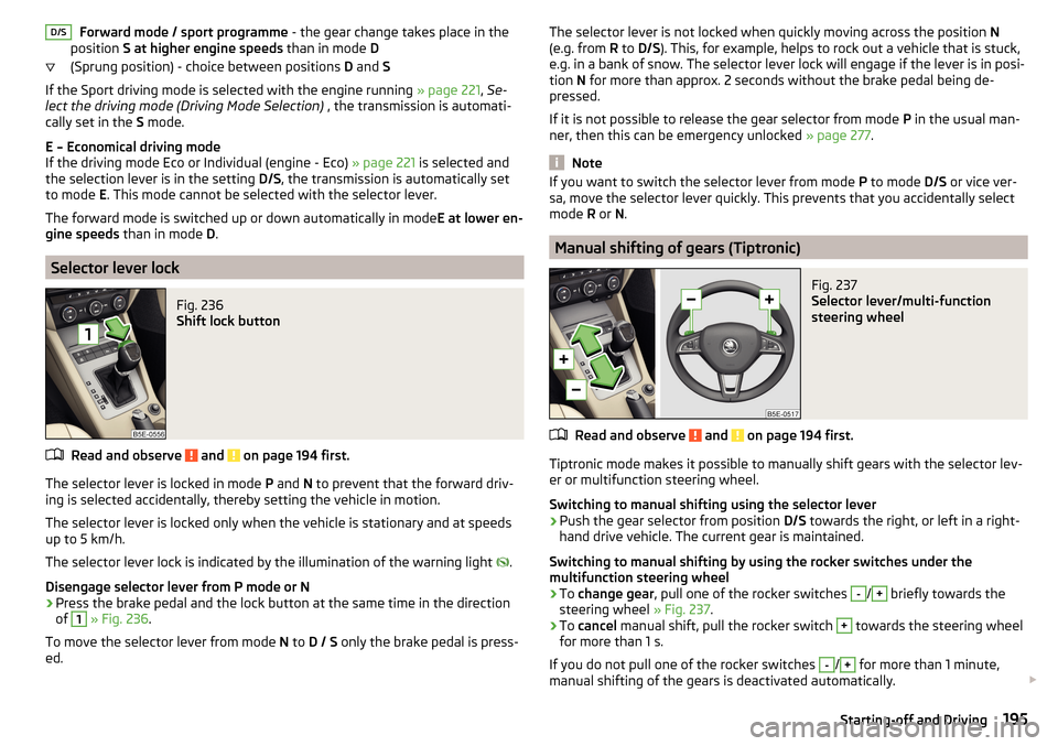
The display of the graphical driving recommendations is in the extra window
Manoeuvre
as well as the display of the instrument cluster.
In the split screen
Manoeuvre
the following driving recommendations are shown
» Fig. 219 .
Street name / street number of the current vehicle position
Driving recommendations with street names / road numbers, with the
route and the travel time to the manoeuvre location
Details of driving recommendation (is displayed near the manoeuvre)
Lane guidance
In the split screen
Manoeuvre
, Infotainment also announces TMC traffic obstruc-
tions and on motorways, car parks, petrol stations or restaurants.
Speed limits
With activated function
→
Advanced settings
→
Note: National border crossed
dis-
play the country-specific speed limits when crossing international borders.
These speed limits can be displayed by tapping the function surface
→
Topspeeds
in the main Navigation menu is displayed.
ABCD180Infotainment
Page 197 of 324
Forward mode / sport programme - the gear change takes place in the
position S at higher engine speeds than in mode D
(Sprung position) - choice between positions D and S
If the Sport driving mode is selected with the engine running » page 221, Se-
lect the driving mode (Driving Mode Selection) , the transmission is automati-
cally set in the S mode.
E – Economical driving mode
If the driving mode Eco or Individual (engine - Eco) » page 221 is selected and
the selection lever is in the setting D/S, the transmission is automatically set
to mode E. This mode cannot be selected with the selector lever.
The forward mode is switched up or down automatically in mode E at lower en-
gine speeds than in mode D.
Selector lever lock
Fig. 236
Shift lock button
Read and observe and on page 194 first.
The selector lever is locked in mode P and N to prevent that the forward driv-
ing is selected accidentally, thereby setting the vehicle in motion.
The selector lever is locked only when the vehicle is stationary and at speeds
up to 5 km/h.
The selector lever lock is indicated by the illumination of the warning light .
Disengage selector lever from P mode or N
›
Press the brake pedal and the lock button at the same time in the direction
of
1
» Fig. 236 .
To move the selector lever from mode N to D / S only the brake pedal is press-
ed.
D/SThe selector lever is not locked when quickly moving across the position N
(e.g. from R to D/S ). This, for example, helps to rock out a vehicle that is stuck,
e.g. in a bank of snow. The selector lever lock will engage if the lever is in posi-
tion N for more than approx. 2 seconds without the brake pedal being de-
pressed.
If it is not possible to release the gear selector from mode P in the usual man-
ner, then this can be emergency unlocked » page 277.
Note
If you want to switch the selector lever from mode P to mode D/S or vice ver-
sa, move the selector lever quickly. This prevents that you accidentally select
mode R or N.
Manual shifting of gears (Tiptronic)
Fig. 237
Selector lever/multi-function
steering wheel
Read and observe and on page 194 first.
Tiptronic mode makes it possible to manually shift gears with the selector lev-
er or multifunction steering wheel.
Switching to manual shifting using the selector lever
›
Push the gear selector from position D/S towards the right, or left in a right-
hand drive vehicle. The current gear is maintained.
Switching to manual shifting by using the rocker switches under the
multifunction steering wheel
›
To change gear , pull one of the rocker switches
-
/
+
briefly towards the
steering wheel » Fig. 237.
›
To cancel manual shift, pull the rocker switch
+
towards the steering wheel
for more than 1 s.
If you do not pull one of the rocker switches
-
/
+
for more than 1 minute,
manual shifting of the gears is deactivated automatically.
195Starting-off and Driving
Page 198 of 324
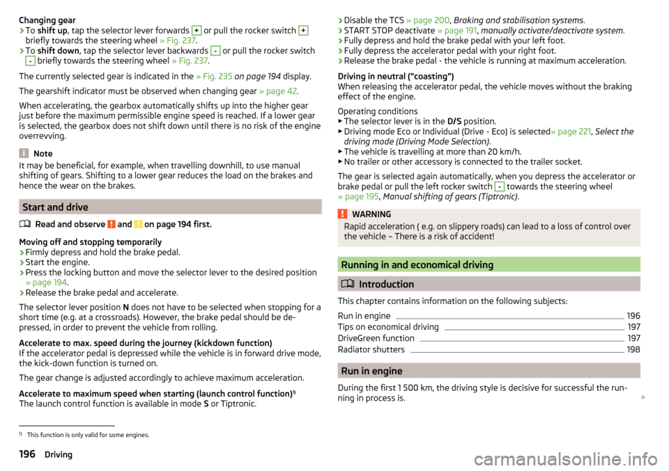
Changing gear›To shift up , tap the selector lever forwards + or pull the rocker switch +
briefly towards the steering wheel » Fig. 237.
›
To shift down , tap the selector lever backwards
-
or pull the rocker switch
-
briefly towards the steering wheel » Fig. 237.
The currently selected gear is indicated in the » Fig. 235 on page 194 display.
The gearshift indicator must be observed when changing gear » page 42.
When accelerating, the gearbox automatically shifts up into the higher gear
just before the maximum permissible engine speed is reached. If a lower gear
is selected, the gearbox does not shift down until there is no risk of the engine
overrevving.
Note
It may be beneficial, for example, when travelling downhill, to use manual
shifting of gears. Shifting to a lower gear reduces the load on the brakes and
hence the wear on the brakes.
Start and drive
Read and observe
and on page 194 first.
Moving off and stopping temporarily
›
Firmly depress and hold the brake pedal.
›
Start the engine.
›
Press the locking button and move the selector lever to the desired position
» page 194 .
›
Release the brake pedal and accelerate.
The selector lever position N does not have to be selected when stopping for a
short time (e.g. at a crossroads). However, the brake pedal should be de-
pressed, in order to prevent the vehicle from rolling.
Accelerate to max. speed during the journey (kickdown function)
If the accelerator pedal is depressed while the vehicle is in forward drive mode,
the kick-down function is turned on.
The gear change is adjusted accordingly to achieve maximum acceleration.
Accelerate to maximum speed when starting (launch control function) 1)
The launch control function is available in mode S or Tiptronic.
› Disable the TCS
» page 200, Braking and stabilisation systems .›START STOP deactivate » page 191, manually activate/deactivate system .›
Fully depress and hold the brake pedal with your left foot.
›
Fully depress the accelerator pedal with your right foot.
›
Release the brake pedal - the vehicle is running at maximum acceleration.
Driving in neutral (“coasting”)
When releasing the accelerator pedal, the vehicle moves without the braking
effect of the engine.
Operating conditions
▶ The selector lever is in the D/S position.
▶ Driving mode Eco or Individual (Drive - Eco) is selected » page 221, Select the
driving mode (Driving Mode Selection) .
▶ The vehicle is travelling at more than 20 km/h.
▶ No trailer or other accessory is connected to the trailer socket.
The gear is selected again automatically, when you depress the accelerator or
brake pedal or pull the left rocker switch
-
towards the steering wheel
» page 195 , Manual shifting of gears (Tiptronic) .
WARNINGRapid acceleration ( e.g. on slippery roads) can lead to a loss of control over
the vehicle – There is a risk of accident!
Running in and economical driving
Introduction
This chapter contains information on the following subjects:
Run in engine
196
Tips on economical driving
197
DriveGreen function
197
Radiator shutters
198
Run in engine
During the first 1 500 km, the driving style is decisive for successful the run-
ning in process is.
1)
This function is only valid for some engines.
196Driving
Page 204 of 324
XDS is an extension to the electronic differential lock (EDL). XDS does not re-
spond to the relieved inner curve wheel of the driven axle in the case of fast
cornering.
By applying braking force to the relieved wheel, spinning is prevented by the
XDS. This has a positive effect on the driving stability and steerability of the
vehicle.
Active steering assist (DSR)
Read and observe
on page 200 first.
The DSR indicates to the driver in critical situations a steering recommenda-tion in order to stabilise the vehicle. DSR is activated, for example, on the right
and left vehicle side when braking sharply on different road surfaces.
Brake Assist (HBA)
Read and observe
on page 200 first.
HBA increases the braking effect and helps to shorten the braking distance.The HBA is activated by the very quick operation of the brake pedal. To ach-
ieve the shortest possible braking distance, the brake pedal must be applied
firmly until the vehicle has come to a complete standstill.
The HBA is automatically switched off when the brake pedal is released.
Hill Start Assist (HHC)
Read and observe
on page 200 first.
When moving off on a gradient, HHC allows you to move your foot from thebrake pedal to the accelerator pedal without the vehicle rolling downhill.
The vehicle is braked by the system for about 2 seconds after releasing the
brake pedal.
The HHC is active on gradients upwards of 5 % if the driver door is closed. HHC
is always active on slopes when in forward or reverse start off.
Multicollision brake (MCB)
Read and observe
on page 200 first.
MCB helps to decrease speed after a collision by means of automatic braking
interventions and to stabilise the vehicle. This reduces the risk of a subse-
quent crash due to uncontrolled vehicle movement.
The automatic brake interventions can take place only if the following condi-
tions are met.
A head-on or side collision occurred.
The impact speed was greater than approx. 10 km/h.
The brakes, the ESL and other required electrical systems remain function-
al after impact.
The accelerator pedal is not actuated.
Trailer stabilisation system (TSA)
Read and observe
on page 200 first.
The TSA helps the combination stable in situations where the trailer sways
and then the whole trailer combination.
TSA brakes the individual wheels of the towing vehicle in order to damp the rocking motion of the entire vehicle combination.
The following conditions are required for the correct TSA function. The trailer was shipped from the factory or purchased from the ŠKODA
genuine accessories.
The trailer is electrically connected to the towing vehicle by means of the
trailer socket.
The parking aid is activated.
The speed is greater than 60 km/h.
Further information » page 230, Towing device and trailer .
202Driving