ESP SKODA OCTAVIA TOUR 2009 1.G / (1U) Owner's Manual
[x] Cancel search | Manufacturer: SKODA, Model Year: 2009, Model line: OCTAVIA TOUR, Model: SKODA OCTAVIA TOUR 2009 1.G / (1U)Pages: 226, PDF Size: 13.11 MB
Page 5 of 226
Contents
4Driving Tips
. . . . . . . . . . . . . . . . . . . . . . . . . . . . . .
Intelligent Technology
. . . . . . . . . . . . . . . . . . . . . . . .
Electronic stability programme (ESP)* . . . . . . . . . .
Brakes . . . . . . . . . . . . . . . . . . . . . . . . . . . . . . . . . . . . . . .
Brake booster . . . . . . . . . . . . . . . . . . . . . . . . . . . . . . . .
Antilock brake system (ABS)* . . . . . . . . . . . . . . . . . .
Brake Assist* . . . . . . . . . . . . . . . . . . . . . . . . . . . . . . . . .
Driving and the Environment
. . . . . . . . . . . . . . . . .
The first 1 500 kilometres and then afterwards . .
Catalytic converter . . . . . . . . . . . . . . . . . . . . . . . . . . . .
Driving in an economical and environmentally
conscious manner . . . . . . . . . . . . . . . . . . . . . . . . . . . .
Environmental compatibility . . . . . . . . . . . . . . . . . . .
Motoring abroad . . . . . . . . . . . . . . . . . . . . . . . . . . . . .
Avoiding damage to your vehicle . . . . . . . . . . . . . .
To w i n g a t r a i l e r
. . . . . . . . . . . . . . . . . . . . . . . . . . . . . . . .
Towing a trailer . . . . . . . . . . . . . . . . . . . . . . . . . . . . . . .
Detachable towing device* . . . . . . . . . . . . . . . . . . . .
General Maintenance
. . . . . . . . . . . . . . .
Taking care of your ve hicle and cleaning the
vehicle
. . . . . . . . . . . . . . . . . . . . . . . . . . . . . . . . . . . . . . . . .
General . . . . . . . . . . . . . . . . . . . . . . . . . . . . . . . . . . . . . .
Care of the exterior of vehicle . . . . . . . . . . . . . . . . . .
Care of the interior of vehicle . . . . . . . . . . . . . . . . . .
Fuel
. . . . . . . . . . . . . . . . . . . . . . . . . . . . . . . . . . . . . . . . . . . .
Petrol . . . . . . . . . . . . . . . . . . . . . . . . . . . . . . . . . . . . . . . .
Diesel . . . . . . . . . . . . . . . . . . . . . . . . . . . . . . . . . . . . . . .
Refuelling . . . . . . . . . . . . . . . . . . . . . . . . . . . . . . . . . . . .
Emergency release of fuel filler flap . . . . . . . . . . . .
Inspecting and replenishing
. . . . . . . . . . . . . . . . . .
Engine compartment . . . . . . . . . . . . . . . . . . . . . . . . .
Engine oil . . . . . . . . . . . . . . . . . . . . . . . . . . . . . . . . . . . .
Cooling system . . . . . . . . . . . . . . . . . . . . . . . . . . . . . . .
Brake fluid . . . . . . . . . . . . . . . . . . . . . . . . . . . . . . . . . . . Battery . . . . . . . . . . . . . . . . . . . . . . . . . . . . . . . . . . . . . . .
Windshield washer system . . . . . . . . . . . . . . . . . . . .
Wheels and Tyres
. . . . . . . . . . . . . . . . . . . . . . . . . . . . . .
Wheels . . . . . . . . . . . . . . . . . . . . . . . . . . . . . . . . . . . . . .
Accessories, changes and replacement of partsAccessories and replacement parts . . . . . . . . . . . . .
Technical changes . . . . . . . . . . . . . . . . . . . . . . . . . . . .Breakdown assistance
. . . . . . . . . . . . . .
Breakdown assistance
. . . . . . . . . . . . . . . . . . . . . . . .
First-aid box*, Warning triangle* and bulb set . . .
Fire extinguisher* . . . . . . . . . . . . . . . . . . . . . . . . . . . . .
Vehicle tool kit . . . . . . . . . . . . . . . . . . . . . . . . . . . . . . . .
Spray for repairing a tyre* . . . . . . . . . . . . . . . . . . . . .
Tyre repair kit* . . . . . . . . . . . . . . . . . . . . . . . . . . . . . . . .
Spare wheel . . . . . . . . . . . . . . . . . . . . . . . . . . . . . . . . . .
Changing a wheel . . . . . . . . . . . . . . . . . . . . . . . . . . . . .
Jump-starting . . . . . . . . . . . . . . . . . . . . . . . . . . . . . . . .
Tow-starting and towing vehicle . . . . . . . . . . . . . . .
Fuses and light bulbs
. . . . . . . . . . . . . . . . . . . . . . . . . .
Electric fuses . . . . . . . . . . . . . . . . . . . . . . . . . . . . . . . . .
Bulbs . . . . . . . . . . . . . . . . . . . . . . . . . . . . . . . . . . . . . . . .
Technical Data
. . . . . . . . . . . . . . . . . . . . . . . . . .
Technical Data
. . . . . . . . . . . . . . . . . . . . . . . . . . . . . . . . .
General information . . . . . . . . . . . . . . . . . . . . . . . . . .
Used abbreviations . . . . . . . . . . . . . . . . . . . . . . . . . . .
Performances . . . . . . . . . . . . . . . . . . . . . . . . . . . . . . . .
Weight . . . . . . . . . . . . . . . . . . . . . . . . . . . . . . . . . . . . . . .
Identification details . . . . . . . . . . . . . . . . . . . . . . . . . .
Fuel consumption according to the regulations
(99/100/EU) . . . . . . . . . . . . . . . . . . . . . . . . . . . . . . . . . .
Dimensions . . . . . . . . . . . . . . . . . . . . . . . . . . . . . . . . . .
1.4 ltr./55 kW - EU4 . . . . . . . . . . . . . . . . . . . . . . . . . . .
1.6 ltr./75 kW - EU4/EU2 DDK . . . . . . . . . . . . . . . . . .
1.8 ltr./110 kW - EU4/EU3D . . . . . . . . . . . . . . . . . . . . 1.9 ltr./66 kW TDI - EU3 . . . . . . . . . . . . . . . . . . . . . . . .
1.9 ltr./74 kW TDI PD - EU4 . . . . . . . . . . . . . . . . . . . .
Vehicles of the Octavia Combi group N1 . . . . . . . .
Vehicles of the Octavia Combi group - Vehicles for
reconstruction . . . . . . . . . . . . . . . . . . . . . . . . . . . . . . . .
Index
. . . . . . . . . . . . . . . . . . . . . . . . . . . . . . . . . . . . . . . .
133
133
133
135
136
137
137
139
139
140
140
143
144
144
145
145
147
149
149
149
149
154
157
157
157
158
159
161
161
164
167
169 170
174
175
175
181
181
181
183
183
183
183
184
184
184
185
185
190
191
194
194
197
203
203
203
203
203
203
203
204
205
206
208
210212
214
216
216
217
s2ig.book Page 4 Monday, November 10, 2008 11:20 AM
Page 7 of 226
Layout of this Owner's Manual (explanations)
6Layout of this Owner's Manual (explanations)The Owner's Manual has been systematically designed, in order to make it easy for
you to find and absorb the information you require.Chapters, table of contents and subject indexThe text of the manual are divided into relatively short sections which are
combined into easy-to-read chapters. The chapter you are reading at any partic-
ular moment is highlighted at the bottom right of the page.
The Table of contents is arranged according to the chapters and the detailed
Subject index at the end of the Owner's Manual helps you to rapidly find the infor-
mation you are looking for.SectionsThe majority of Sections apply to all models.
Since there is a wide range of different equipment and options available it is clearly
unavoidable, despite dividing the contents into sections, that mention may be
made of equipment which is not fitted to your vehicle.Brief information and instructionsEach section has a Heading.
This is followed by Brief information (in large italic lettering), which tells you the
subject which is dealt with in this section.
Most of the illustrations are accompanied by an Instruction (in relatively large
letters) which explains to you in a straig htforward way the action you have to take.
Work steps which have to be carried out are illustrated with a hyphen.Direction indicationsAll direction indications such as “left”, “right ”, “front”, “rear” relate to the direction
of travel of the vehicle.Explanation of symbols* Equipment which is marked in such a wa y is only standard on certain vehicle
model versions or only suppliable as optional equipment for certain models. End of a section.
The section is continued on the next page.NotesAll four kinds of notes, which are used in th e text, are always stated at the end of the
respective section.
WARNING
The most important notes are marked with the heading WARNING. These
WARNING notes draw your attention to a serious risk of accident or injury.
While reading the text you will frequently encounter a double arrow
followed by a small warning symbol. This symbol is intended to draw your
attention to a WARNING note at the end of the section to which you must pay
careful attention.
Caution
A Caution note draws your attention to the possibility of damage to your vehicle
(e.g. damage to gearbox), or points out general risks of an accident.
For the sake of the environment
An Environmental note draws your attention to environmental protection
aspects. This is where you will, for example, find tips aimed at reducing your fuel
consumption.
Note
A normal Note draws your attention in a general way to important information.
s2ig.book Page 6 Monday, November 10, 2008 11:20 AM
Page 10 of 226
Cockpit9
Using the system
Safety
Driving Tips
General Maintenance
Breakdown assistance
Technical Data
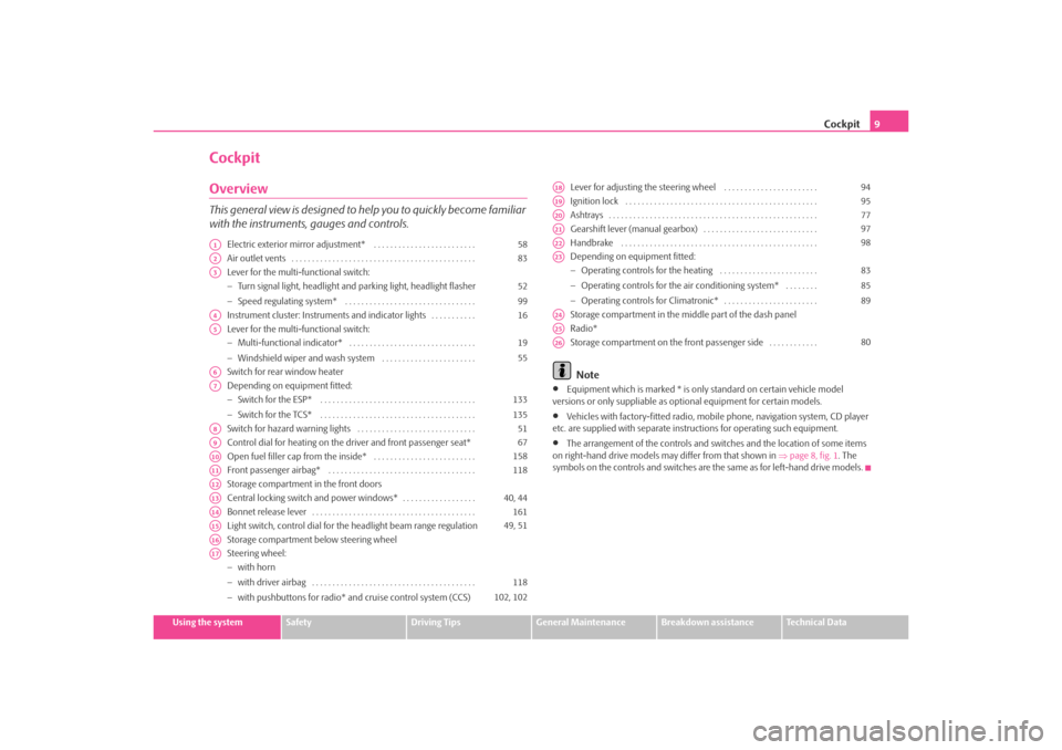
CockpitOverviewThis general view is designed to help you to quickly become familiar
with the instruments, gauges and controls.
Electric exterior mirror adjustment* . . . . . . . . . . . . . . . . . . . . . . . . .
Air outlet vents . . . . . . . . . . . . . . . . . . . . . . . . . . . . . . . . . . . . . . . . . . . . .
Lever for the multi-functional switch:
−Turn signal light, headlight and parking light, headlight flasher
− Speed regulating system* . . . . . . . . . . . . . . . . . . . . . . . . . . . . . . . .
Instrument cluster: Instrum ents and indicator lights . . . . . . . . . . .
Lever for the multi-functional switch:
− Multi-functional indicator* . . . . . . . . . . . . . . . . . . . . . . . . . . . . . . .
− Windshield wiper and wash system . . . . . . . . . . . . . . . . . . . . . . .
Switch for rear window heater
Depending on equipment fitted:
− Switch for the ESP* . . . . . . . . . . . . . . . . . . . . . . . . . . . . . . . . . . . . . .
− Switch for the TCS* . . . . . . . . . . . . . . . . . . . . . . . . . . . . . . . . . . . . . .
Switch for hazard warning lights . . . . . . . . . . . . . . . . . . . . . . . . . . . . .
Control dial for heating on the driver and front passenger seat*
Open fuel filler cap from the inside* . . . . . . . . . . . . . . . . . . . . . . . . .
Front passenger airbag* . . . . . . . . . . . . . . . . . . . . . . . . . . . . . . . . . . . .
Storage compartment in the front doors
Central locking switch and power windows* . . . . . . . . . . . . . . . . . .
Bonnet release lever . . . . . . . . . . . . . . . . . . . . . . . . . . . . . . . . . . . . . . . .
Light switch, control dial for the headlight beam range regulation
Storage compartment below steering wheel
Steering wheel:
− with horn
− with driver airbag . . . . . . . . . . . . . . . . . . . . . . . . . . . . . . . . . . . . . . . .
− with pushbuttons for radio* an d cruise control system (CCS) Lever for adjusting the steering wheel . . . . . . . . . . . . . . . . . . . . . . .
Ignition lock . . . . . . . . . . . . . . . . . . . . . . . . . . . . . . . . . . . . . . . . . . . . . . .
Ashtrays . . . . . . . . . . . . . . . . . . . . . . . . . . . . . . . . . . . . . . . . . . . . . . . . . . .
Gearshift lever (manual gearbox) . . . . . . . . . . . . . . . . . . . . . . . . . . . .
Handbrake . . . . . . . . . . . . . . . . . . . . . . . . . . . . . . . . . . . . . . . . . . . . . . . .
Depending on equipment fitted:
−
Operating controls for the heating . . . . . . . . . . . . . . . . . . . . . . . .
− Operating controls for the air conditioning system* . . . . . . . .
− Operating controls for Climatronic* . . . . . . . . . . . . . . . . . . . . . . .
Storage compartment in the middle part of the dash panel
Radio*
Storage compartment on the front passenger side . . . . . . . . . . . .
Note
•
Equipment which is marked * is only standard on certain vehicle model
versions or only suppliable as op tional equipment for certain models.
•
Vehicles with factory-fitted radio, mobile phone, navigation system, CD player
etc. are supplied with separate instru ctions for operating such equipment.
•
The arrangement of the controls and swit ches and the location of some items
on right-hand drive models may differ from that shown in ⇒page 8, fig. 1 . The
symbols on the controls and switches are the same as for left-hand drive models.
A1
58
A2
83
A3
52
99
A4
16
A5
19
55
A6A7
133
135
A8
51
A9
67
A10
158
A11
118
A12A13
40, 44
A14
161
A15
49, 51
A16A17
118
102, 102
A18
94
A19
95
A20
77
A21
97
A22
98
A23
83
85
89
A24A25A26
80
s2ig.book Page 9 Monday, November 10, 2008 11:20 AM
Page 25 of 226
Instruments and Indicator/Warning Lights
24
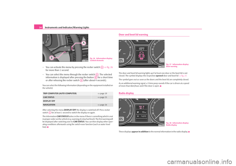
– You can activate the menu by pressing the rocker switch ⇒fig. 26
for more than 1 second.
– You can select the menu through the rocker switch . The selected information is displayed after pressing the button for a short time
or after releasing the rocker switch (after about 4 seconds).You can select the following information (d epending on the equipment installed on
the vehicle):
After selecting the menu DISPLAY OFF the display is switched off. Press rocker
switch for at least 1 second to switch the display on again.
The Information CAR STATUSflashes in the menu if there is something which is not
in proper order on the vehicle (e.g. warning of a low fuel level). The first warning will
be displayed after switching over to CAR STATUS. You can then display other oper-
ating conditions afterwards using the switch-over function (such as water level
low).
Door and boot lid warningThe door and boot lid warning lights up if at least one door or the boot lid is not
closed. The symbol displays the respective opened door and boot lid ⇒fig. 27 .
The symbol goes out as soon as the doors and the boot lid are completely closed.
As an additional warning signal, a 3 time pe ep sounds if the car is driven at a speed
of more than 6km/hour and if the door is open.Radio displayThese displays appear in addition to the normal information in the radio display.
TRIP COMPUTER (AUTO COMPUTER)
⇒page 19
CAR STATUS
⇒page 25
DISPLAY OFFNAVIGATION
⇒page 26
Fig. 26 Information display:
Control elements
AA
AAAB
AA
AA
Fig. 27 Information display:
Door warningFig. 28 Information display:
Radio display
s2ig.book Page 24 Monday, November 10, 2008 11:20 AM
Page 29 of 226
Instruments and Indicator/Warning Lights
28
WARNING
•
If you do not pay attention to the wa rning lights coming on and the corre-
sponding descriptions and warning notes, this may result in severe body
injuries or major vehicle damage.
•
The engine compartment of your car is a hazardous area. There is a risk
of injuries, scalding, accidents and fire when working in the engine compartment, e.g. inspecting and replenis
hing oil and other fluids. It is also
essential to obse rve all warnings ⇒page 162.
Note
•
Arrangement of the indicator lights depends on the model and model version.
The symbols shown in the following function al description are to be found as indi-
cator lights in the instrument cluster.
•
Operational faults are shown in the inst rument cluster as red symbols (priority
1 - danger) or yellow symbols (priority 2 - warning).
Turn signal system
Either the left
or right
indicator light flashes depending on the position of the
turn signal lever.
The indicator light flashes at twice its normal rate if a turn signal light fails. This does
not apply when towing a trailer.
Switching off the hazard warning light system is switched on will cause all of the
turn signal lights as well as both indicator lights to flash.
Further information about the turn signal system ⇒page 52.
Turn signal system for vehicles towing a trailer
*
The warning light
flashes together with the other turn signal lights only if the
vehicle is towing a trailer.
The indicator light does not flash if a turn signal light on the trailer or on the vehicle
is not operating.
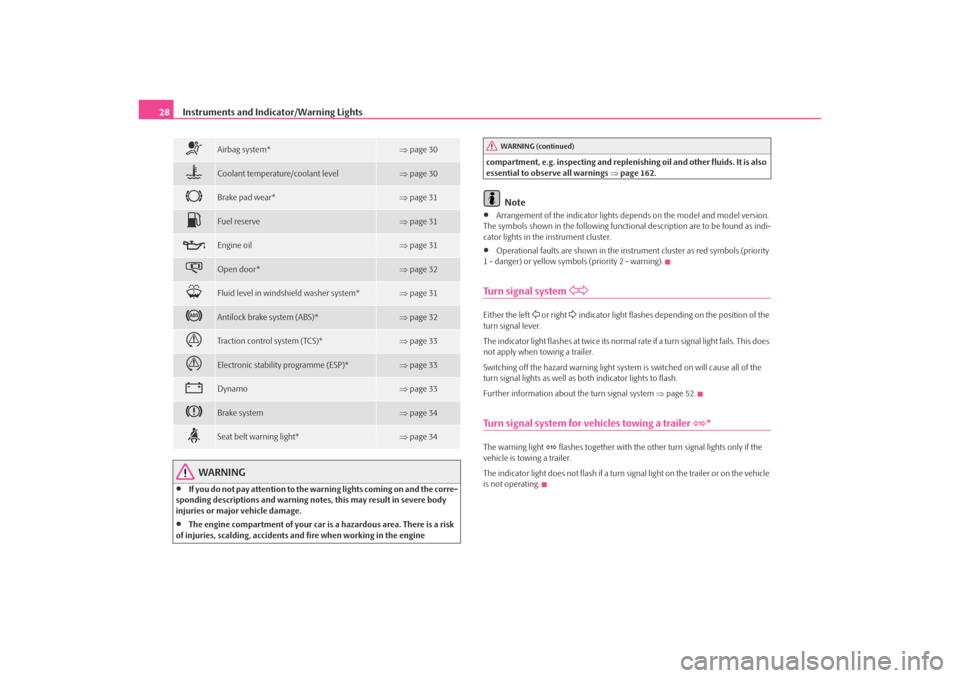
Airbag system*
⇒ page 30
Coolant temperature/coolant level
⇒page 30
Brake pad wear*
⇒page 31
Fuel reserve
⇒page 31
Engine oil
⇒page 31
Open door*
⇒page 32
Fluid level in windshield washer system*
⇒page 31
Antilock brake system (ABS)*
⇒page 32
Traction control system (TCS)*
⇒page 33
Electronic stability programme (ESP)*
⇒page 33
Dynamo
⇒page 33
Brake system
⇒page 34
Seat belt warning light*
⇒page 34
WARNING (continued)
s2ig.book Page 28 Monday, November 10, 2008 11:20 AM
Page 34 of 226
Instruments and Indicator/Warning Lights33
Using the system
Safety
Driving Tips
General Maintenance
Breakdown assistance
Technical Data
Electronic Differential Lock (EDL)*
The EDL is a part of the ABS. A fault in the EDL is indicated by the ABS warning light
in the instrument cluster. Have the vehicle inspected immediately by your
nearest specialist garage.
Models fitted with ESP are equipped with electronic differential lock (EDL).
If a significant fault occurs in the ABS system, a warning signal sounds additionally
(3 peeps).
Further information on the EDL ⇒page 134.
WARNING
•
If the brake system warning light
comes on together with the ABS
warning light
stop the vehicle immediatel y and check the brake fluid
level in the reservoir ⇒page 169, “Brake fluid”. If the fluid level has dropped
below the MIN marking, do not drive any further - risk of accident! Obtain
professional assistance.
•
Pay attention to the following instru ctions before checking the brake
fluid level and opening the bonnet ⇒page 162, “Working in the engine
compartment”.
•
If the brake fluid is at the correct level, the ABS control function has
failed. The rear wheels may then block very rapidly when braking. In certain
circumstances, this can result in the rear end of the car breaking away - risk
of skidding! Drive carefully to the ne arest specialist garage and have the
fault rectified.
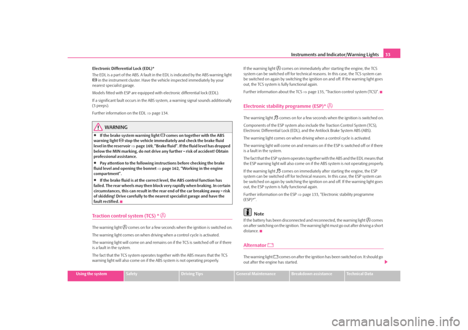
Traction control system (TCS) *
The warning light
comes on for a few seconds when the ignition is switched on.
The warning light comes on when drivin g when a control cycle is activated.
The warning light will come on and remains on if the TCS is switched off or if there
is a fault in the system.
The fact that the TCS system operates together with the ABS means that the TCS
warning light will also come on if the ABS system is not operating properly. If the warning light
comes on immediately after starting the engine, the TCS
system can be switched off for technical reasons. In this case, the TCS system can
be switched on again by swit ching the ignition on and off. If the warning light goes
out, the TCS system is fully functional again.
Further information about the TCS ⇒page 135, “Traction control system (TCS)”.
Electronic stability programme (ESP)*
The warning light
comes on for a few seconds when the ignition is switched on.
Components of the ESP system also incl ude the Traction Control System (TCS),
Electronic Differential Lock (EDL), an d the Antilock Brake System ABS (ABS).
The warning light comes on when driving when a control cycle is activated.
The warning light will come on and remains on if the ESP is switched off or if there
is a fault in the system.
The fact that the ESP system operates together with the ABS and the EDL means that
the ESP warning light will also come on if the ABS system is not operating properly.
If the warning light comes on immediately after starting the engine, the ESP
system can be switched off for technical reasons. In this case, the ESP system can
be switched on again by swit ching the ignition on and off. If the warning light goes
out, the ESP system is fully functional again.
Further information on the ESP ⇒page 133, “Electronic stability programme
(ESP)*”.
Note
If the battery has been disconnected and reconnected, the warning light
comes
on after switching on the ignition. The warn ing light must go out after driving a short
distance.
Alternator
The warning light
comes on after the ignition has been switched on. It should go
out after the engine has started.
s2ig.book Page 33 Monday, November 10, 2008 11:20 AM
Page 45 of 226
Unlocking and locking
44Power windows*Buttons on the driver's doorThe power windows operate only when ignition is switched on. After
switching the ignition off, the power windows can still be operated for
approx. 10 minutes if a front door is opened.
Opening a window
– A window is opened by pressing lightly on the respective button in the
door. The process stops when one releases the button.
– Additionally you can open the window automatically (fully opened) by pressing the button up to the stop. Renewed pressing of the button
causes the window to stop immediately.
Closing a window
– A window is closed through pulling lightly on the respective button in
the door. The closing process stops when one releases the button.
– Additionally you can close the window automatically (fully closed) by pulling the button up to the stop. Renewed pulling of the button
causes the window to stop immediately.
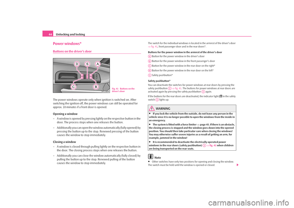
The switch for the individual windows is located in the armrest of the driver's door
⇒fig. 41 , front passenger door and in the rear doors*.
Buttons for the power window in the armrest of th e driver's door
Button for the power window in the driver's door
Button for the power window in the front passenger's door
Button for the power window in the rear door on the right*
Button for the power window in the rear door on the left*
Safety pushbutton*
Safety pushbutton*
You can deactivate the switches for power windows at rear doors by pressing the
safety pushbutton ⇒fig. 41 . The buttons for power windows at rear doors are
activated again by pressing the safety pushbutton again.
If the buttons for the rear doors are deactivated, the indicator light
in the safety
switch lights up.
WARNING
•
If you lock the vehicle from the outside, do not leave any person in the
vehicle since it is no longer possible to open the windows from the inside in
an emergency.
•
The system is fitted with a force limiter ⇒page 45. If there is an obstacle,
the closing process is stopped and the window goes down into the opened
position. You should then take particular care when closing the windows!
You may otherwise suffer severe injuries as a result of getting an arm, for
example, jammed in the window!
•
It is recommended to deactivate the electrically operated power
windows in the rear doors (safety pushbutton) ⇒fig. 41 when children
are being transported on the rear seats.Note
•
Other switches have only two positions for opening and closing the window.
The switch must be held until th e window is opened or closed.
Fig. 41 Buttons on the
driver's door
AAABACADAS
AS
AS
AS
AS
s2ig.book Page 44 Monday, November 10, 2008 11:20 AM
Page 52 of 226
Lights and Visibility51
Using the system
Safety
Driving Tips
General Maintenance
Breakdown assistance
Technical Data
Headlamp range adjustment
Once the low beam is switched on you can then adapt the range of
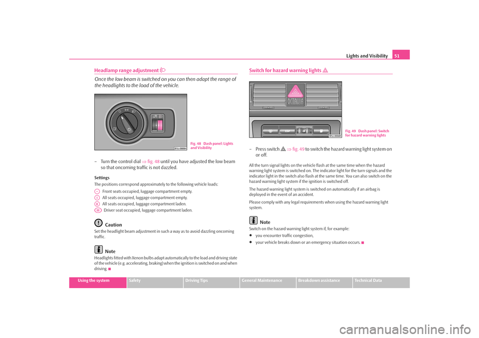
the headlights to the load of the vehicle.– Turn the control dial ⇒fig. 48 until you have adjusted the low beam
so that oncoming traffic is not dazzled.Settings
The positions correspond approximat ely to the following vehicle loads:
Front seats occupied, luggage compartment empty.
All seats occupied, lugg age compartment empty.
All seats occupied, lugg age compartment laden.
Driver seat occupied, lu ggage compartment laden.
Caution
Set the headlight beam adjustment in such a way as to avoid dazzling oncoming
traffic.
Note
Headlights fitted with Xenon bulbs adapt au tomatically to the load and driving state
of the vehicle (e.g. accelerating, braking) when the ignition is switched on and when
driving.
Switch for hazard warning lights
–Press switch
⇒ fig. 49 to switc h the haz ard wa rning lig ht system on
or off.
All the turn signal lights on the vehicle flash at the same time when the hazard
warning light system is switched on. The indicator light for the turn signals and the
indicator light in the switch also flash at the same time. You can also switch on the
hazard warning light system if the ignition is switched off.
The hazard warning light system is switched on automatically if an airbag is
deployed in the event of an accident.
Please comply with any legal requirements when using the hazard warning light
system.
Note
Switch on the hazard warning light system if, for example:•
you encounter traffic congestion,
•
your vehicle breaks down or an emergency situation occurs.
Fig. 48 Dash panel: Lights
and Visibility
A-AIAIIAIII
Fig. 49 Dash panel: Switch
for hazard warning lights
s2ig.book Page 51 Monday, November 10, 2008 11:20 AM
Page 53 of 226
Lights and Visibility
52The turn signal
and main beam lever
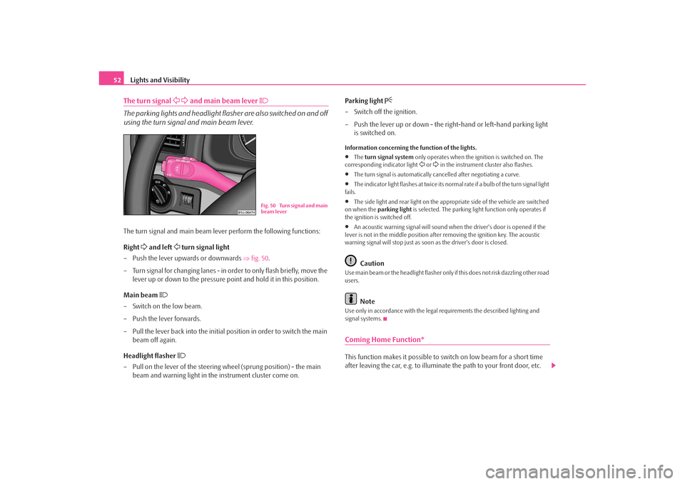
The parking lights and headlight flasher are also switched on and off
using the turn signal and main beam lever.The turn signal and main beam lever perform the following functions:
Right
and left
turn signal light
– Push the lever upwards or downwards ⇒fig. 50 .
– Turn signal for changing lanes - in or der to only flash briefly, move the
lever up or down to the pressure point and hold it in this position.
Main beam
– Switch on the low beam.
– Push the lever forwards.
– Pull the lever back into the initial position in order to switch the main beam off again.
Headlight flasher
– Pull on the lever of the steering wheel (sprung position) - the main
beam and warning light in the instrument cluster come on. Parking light
– Switch off the ignition.
– Push the lever up or down - the ri
ght-hand or left-hand parking light
is switched on.Information concerning the function of the lights.•
The turn signal system only operates when the ignition is switched on. The
corresponding indicator light
or in the instrument cluster also flashes.
•
The turn signal is automatically cancelled after negotiating a curve.
•
The indicator light flashes at twice its normal rate if a bulb of the turn signal light
fails.
•
The side light and rear light on the appr opriate side of the vehicle are switched
on when the parking light is selected. The parking light function only operates if
the ignition is switched off.
•
An acoustic warning signal will sound when the driver's door is opened if the
lever is not in the middle position after removing the ignition key. The acoustic
warning signal will stop just as s oon as the driver's door is closed.Caution
Use main beam or the headlight flasher only if this does not risk dazzling other road
users.
Note
Use only in accordance with the legal requirements the described lighting and
signal systems.Coming Home Function*This function makes it possible to sw itch on low beam for a short time
after leaving the car, e.g. to illumina te the path to your front door, etc.
Fig. 50 Turn signal and main
beam lever
s2ig.book Page 52 Monday, November 10, 2008 11:20 AM
Page 57 of 226
Lights and Visibility
56
Fast wipe
– Position the lever up into position .
Automatic wipe/wash for windscreen
– Pull the lever towards the steering wheel into the spring-tensioned position , the windscreen wiper and wash system will operate
immediately.
– Release the lever. The windscreen wash system stops and the wiper continues for another 1 - 3 wiper stro kes (depending on the period of
spraying of the windscreen).
Rain sensor*
– Move the lever into position .
– You can set the sensitivity of the sensor individually with switch .
– After switching off the ignition, you must then once again activate the
sensor by moving the lever into position , and then back into posi-
tion .
Wiping the rear window pane*
– Push the lever away from the steering wheel into position - the widescreen wiper will operate every 6 seconds.
Automatic wipe/wash for the rear window pane*
– Push the lever away from the steering wheel into the spring-tensioned position , the windscreen wiper and wash system will operate. As
long as you hold the lever in this position, the wiper and the wash
system operate - spring -tensioned position.
– Letting go of the lever will cause the windscreen wash system to stop and the wiper to continue for anot her 1 - 3 wiper strokes (depending
on the period of spraying of the windscreen). The lever will stay in
position after releasing it . Switching windscreen wipers off
– Move the lever back into its home position .
The windscreen wipers and the windscreen washer system only operate if the igni-
tion is switched on.
The rain sensor* automatically regulates
the break between the individual wiper
strokes depending on the intensity of the rain.
The windscreen washer nozzles are heated* when the ignition is switched on.
Top up with wash liquid ⇒page 174.
WARNING
•
Properly maintained windscreen wi per blades are essential for clear
visibility and safe driving ⇒page 57, “Replacing wiper blades for the wind-
screen wipers”.
•
Do not use the windscreen washer system at low temperatures, without
heating the windscreen beforehand. Otherwise the window cleaner could
freeze on the windscreen and re strict the view to the front.
•
The rain sensor only operates as a support. The driver is not released
from the responsibility to set the function of the windscreen wipers manu-
ally depending on the visibility conditions.Caution
In frosty weather, please first of all check whether the windscreen wiper blades are
not frozen to the windscreen before switching them on. Switching on windscreen
wipers when the blades are frozen to the windscreen may result in damage both to
the blades and the motor of the windscreen wipers!Headlight cleaning system*After each wash cycle of the windscreen an d if the parking lights, low beam light or
main beam light are switched on, the headlights are also cleaned.
A3
A5
A1
AA
A0
A1
A6
A7
A6
A0
s2ig.book Page 56 Monday, November 10, 2008 11:20 AM