roof SKODA OCTAVIA TOUR 2009 1.G / (1U) Owner's Manual
[x] Cancel search | Manufacturer: SKODA, Model Year: 2009, Model line: OCTAVIA TOUR, Model: SKODA OCTAVIA TOUR 2009 1.G / (1U)Pages: 226, PDF Size: 13.11 MB
Page 3 of 226
Introduction
2
On-board literature
The on-board literature for your vehicle consists of this “ Owner's
Manual ” as well as the brochures “ Quick Reference Guide”, “Service
Schedule ” and “Help on the road ”. There can also be a variety of other
additional operating manuals and instructions on-board (e.g. an oper-
ating manual for the radio) depending on the vehicle model and equip-
ment.
If one of the publications listed above is missing, please contact a
specialist garage immediately, where on e will be glad to assist you in such
matters.
One should note that the details give n in the vehicle's papers always
take precedence over those in the Owner's Manual.
Owner's Manual
This Owner's Manual describes the current scope of equipment.
Certain items of equipment listed ar e only installed later on and only
envisaged for particular markets. The illustrations can differ in minor
details from your vehicle; they are only intended for general information.
In addition to information regarding all the controls and equipment, the
Owner's Manual also contains import ant information regarding care and
operation for your safety and also to retain the value of your vehicle. To
provide you with valuable tips and aids. You can learn how how you can
operate your vehicle safely, economically and in an environmentally
conscious way.
For safety reasons, please also pay attention to the information on
accessories, modifications and replacement of parts ⇒ page 181.
The other chapters of the Owner's Manual are also important, however,
for proper treatment of your car - in addition to regular care and mainte-
nance - helps to retain its value and in many cases is also one of the
conditions for possible warranty claims. The Service schedule
contains:
•
Vehicle data,
•
Service intervals,
•
Overview of the service work,
•
Service proof,
•
Confirmation of mo
bility warranty,
•
important information on the warranty.
The confirmations of the carried out service work are one of the condi-
tions for possible warranty claims.
Please always present th e Service schedule when you take your car to a
specialist garage.
If the Service schedule is missing or worn, please contact the specialist
garage, where your car is serviced regularly. You will receive a duplicate,
in which the previously carried out service work are confirmed.
Help on the road
contains the addresses and telephone numbers of Škoda Importers.
s2ig.book Page 2 Monday, November 10, 2008 11:20 AM
Page 4 of 226
Contents3
ContentsLayout of this Owner's Manual
(explanations)
. . . . . . . . . . . . . . . . . . . . . . . . . .
Using the system
. . . . . . . . . . . . . . . . . . . . . .
Cockpit
. . . . . . . . . . . . . . . . . . . . . . . . . . . . . . . . . . . . . . . .
Overview . . . . . . . . . . . . . . . . . . . . . . . . . . . . . . . . . . . .
The brief instruction
. . . . . . . . . . . . . . . . . . . . . . . . . .
Basic functions and important information . . . . .
Instruments and Indicator/Warning Lights
. . .
General view of the instrument cluster . . . . . . . . .
Engine revolutions counter . . . . . . . . . . . . . . . . . . . .
Coolant temperature gauge . . . . . . . . . . . . . . . . . . .
Fuel gauge . . . . . . . . . . . . . . . . . . . . . . . . . . . . . . . . . . .
Speedometer . . . . . . . . . . . . . . . . . . . . . . . . . . . . . . . .
Counter for distance driven . . . . . . . . . . . . . . . . . . .
Service Interval Display . . . . . . . . . . . . . . . . . . . . . . .
Digital clock . . . . . . . . . . . . . . . . . . . . . . . . . . . . . . . . . .
Multi-functional indicator (onboard computer)*
Information display* . . . . . . . . . . . . . . . . . . . . . . . . . .
Auto Check Control . . . . . . . . . . . . . . . . . . . . . . . . . . .
Warning lights . . . . . . . . . . . . . . . . . . . . . . . . . . . . . . . .
Unlocking and locking
. . . . . . . . . . . . . . . . . . . . . . . .
Key . . . . . . . . . . . . . . . . . . . . . . . . . . . . . . . . . . . . . . . . . .
Changing the battery of the radio remote control
Electronic immobiliser . . . . . . . . . . . . . . . . . . . . . . . .
Locking . . . . . . . . . . . . . . . . . . . . . . . . . . . . . . . . . . . . . .
Child safety lock . . . . . . . . . . . . . . . . . . . . . . . . . . . . . .
Central locking system* . . . . . . . . . . . . . . . . . . . . . . .
Remote control* . . . . . . . . . . . . . . . . . . . . . . . . . . . . . .
Synchonisation of the remote control . . . . . . . . . .
Anti-theft alarm system* . . . . . . . . . . . . . . . . . . . . . . Power windows* . . . . . . . . . . . . . . . . . . . . . . . . . . . . .
Electric sliding/tilting roof* . . . . . . . . . . . . . . . . . . . .
Lights and Visibility
. . . . . . . . . . . . . . . . . . . . . . . . . . .
Lights . . . . . . . . . . . . . . . . . . . . . . . . . . . . . . . . . . . . . . . .
Interior lighting . . . . . . . . . . . . . . . . . . . . . . . . . . . . . . .
Visibility . . . . . . . . . . . . . . . . . . . . . . . . . . . . . . . . . . . . .
Windshield wiper and wash system . . . . . . . . . . . .
Rear-view mirror . . . . . . . . . . . . . . . . . . . . . . . . . . . . .
Seats and Storage
. . . . . . . . . . . . . . . . . . . . . . . . . . . . .
Front seats . . . . . . . . . . . . . . . . . . . . . . . . . . . . . . . . . . .
Adjusting front seats electrically* . . . . . . . . . . . . . .
Head restraints . . . . . . . . . . . . . . . . . . . . . . . . . . . . . . .
Rear seats . . . . . . . . . . . . . . . . . . . . . . . . . . . . . . . . . . . .
Pedals . . . . . . . . . . . . . . . . . . . . . . . . . . . . . . . . . . . . . . .
luggage compartment . . . . . . . . . . . . . . . . . . . . . . . .
Net partition (Combi)* . . . . . . . . . . . . . . . . . . . . . . . .
The roof rack* . . . . . . . . . . . . . . . . . . . . . . . . . . . . . . . .
Note holder . . . . . . . . . . . . . . . . . . . . . . . . . . . . . . . . . .
Ashtray* . . . . . . . . . . . . . . . . . . . . . . . . . . . . . . . . . . . . .
Cigarette lighter*, power sockets . . . . . . . . . . . . . . .
Storage compartments . . . . . . . . . . . . . . . . . . . . . . . .
Heating and air conditioning system
. . . . . . . . .
Air outlet vents . . . . . . . . . . . . . . . . . . . . . . . . . . . . . . .
Heating . . . . . . . . . . . . . . . . . . . . . . . . . . . . . . . . . . . . . .
Air conditioning system* . . . . . . . . . . . . . . . . . . . . . .
Climatronic* (automatic air conditioning) . . . . . .
Starting-off and Driving
. . . . . . . . . . . . . . . . . . . . . . .
Setting steering wheel position . . . . . . . . . . . . . . . .
Ignition lock . . . . . . . . . . . . . . . . . . . . . . . . . . . . . . . . . .
Starting the engine . . . . . . . . . . . . . . . . . . . . . . . . . . .
Switching off the engine . . . . . . . . . . . . . . . . . . . . . . .
Shifting . . . . . . . . . . . . . . . . . . . . . . . . . . . . . . . . . . . . . .
Handbrake . . . . . . . . . . . . . . . . . . . . . . . . . . . . . . . . . . . Rear parking aid* . . . . . . . . . . . . . . . . . . . . . . . . . . . . .
Cruise control system (CCS)* . . . . . . . . . . . . . . . . . .
Communication
. . . . . . . . . . . . . . . . . . . . . . . . . . . . . .
Multifunction steering wheel* . . . . . . . . . . . . . . . . .
Mobile phone, handsfree-system* . . . . . . . . . . . . .
Mobile phones and two-way radio systems . . . . .
Safety
. . . . . . . . . . . . . . . . . . . . . . . . . . . . . . . . . . . . . .
Passive Safety
. . . . . . . . . . . . . . . . . . . . . . . . . . . . . . . . .
Basic information . . . . . . . . . . . . . . . . . . . . . . . . . . . .
Correct seated position . . . . . . . . . . . . . . . . . . . . . . .
Seat belts
. . . . . . . . . . . . . . . . . . . . . . . . . . . . . . . . . . . . . .
Why seat belts? . . . . . . . . . . . . . . . . . . . . . . . . . . . . . .
The physical principle of a frontal collision . . . . .
Important safety information regarding the use of
seat belts . . . . . . . . . . . . . . . . . . . . . . . . . . . . . . . . . . . .
How are seat belts correctly fastened? . . . . . . . . .
Belt tensioners . . . . . . . . . . . . . . . . . . . . . . . . . . . . . . .
Airbag system
. . . . . . . . . . . . . . . . . . . . . . . . . . . . . . . . .
Description of the airbag system . . . . . . . . . . . . . . .
Front airbag . . . . . . . . . . . . . . . . . . . . . . . . . . . . . . . . . .
Side airbags* . . . . . . . . . . . . . . . . . . . . . . . . . . . . . . . . .
Deactivating an airbag . . . . . . . . . . . . . . . . . . . . . . . .
Transporting children safely
. . . . . . . . . . . . . . . . . .
What you should know about transporting
children! . . . . . . . . . . . . . . . . . . . . . . . . . . . . . . . . . . . . .
Child seat . . . . . . . . . . . . . . . . . . . . . . . . . . . . . . . . . . . .
Attaching a child seat using the “ISOFIX” system
6
7
9
9
10
10
16
16
16
16
17
17
18
18
19
19
23
25
27
35
35
36
36
37
37
38
41
42
43 44
46
49
49
53
54
55
58
60
60
61
64
65
67
68
73
75
77
77
78
79
83
83
83
85
89
94
94
95
95
97
97
9898
99
102
102
103
104
105
105
105
106
110
110
111
111
112
115
117
117
118
121
122
125
125
128
131
s2ig.book Page 3 Monday, November 10, 2008 11:20 AM
Page 40 of 226
Unlocking and locking39
Using the system
Safety
Driving Tips
General Maintenance
Breakdown assistance
Technical Data
The safe securing system is again activa
ted the next time the vehicle is unlocked
and locked again.
The doors can be opened from the inside if the vehicle is locked and the safe
securing system is deactivated:
•
The door is unlocked by actuating the door-opening lever.
•
The door opens upon actuating the door-opening lever again.
WARNING
If the vehicle is locked from the outside and the safe securing system is acti-
vated, there must not be any person and animals in the vehicle as it is then
not possible to open either a door or a window from the inside. The locked
doors make it more difficult for rescuers to get into the vehicle in an emer-
gency - hazard!
Note
The anti-theft alarm system* is also activated with the deactivated safe securing
system when locking the vehicle. The interior monitor* is however not activated.Unlocking the vehicle using the key
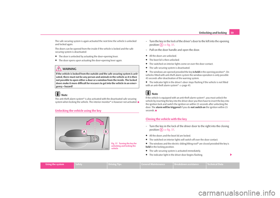
– Turn the key in the lock of the driver 's door to the left into the opening
position ⇒fig. 37 .
– Pull on the door handle and open the door.•
All the doors are unlocked.
•
The boot lid is then unlocked.
•
The switched on interior lights come on over the door contact.
•
The safe securing system is deactivated.
•
The windows are opened provided the key is held in the opening position*. On
vehicles fitted with anti-the ft alarm system the window operation is only possible
45 seconds after deactivation of the warning system.
•
The indicator light in the driver's door stops flashing if the vehicle is not fitted
with an anti-theft alarm system* ⇒page 43.Note
If the vehicle is equipped with an anti-theft alarm system*, you must unlock the
vehicle by inserting the key into the driver door you then have to insert the key into
the ignition lock and switch the ignition on within 15 seconds after unlocking the
door. The alarm will be triggered if you do not switch on the ignition within 15
seconds.Closing the vehicle with the key– Turn the key in the lock of the driver door to the right into the closing
position ⇒fig. 37 .•
All the doors and the boot lid are locked.
•
The switched on interior lights will switch off over the door contact.
•
The windows and the electric sliding/tiltin g roof* are closed provided the key is
held in the locking position.
•
The safe securing system is activated immediately.
•
The indicator light in the driver door begins flashing.
Fig. 37 Turning the key for
unlocking and locking the
vehicle
AAAB
s2ig.book Page 39 Monday, November 10, 2008 11:20 AM
Page 44 of 226
Unlocking and locking43
Using the system
Safety
Driving Tips
General Maintenance
Breakdown assistance
Technical Data
ated a number of times outside of the operative range of the equipment or the
battery on the remote control was replaced.
This means it is necessary to synchronise the code as follows:
•
Press any button on the remote control.
•
pressing of the button means that the door will unlock with the key within 1
minute.
Anti-theft alarm system*DescriptionThe anti-theft alarm system increases the le vel of protection against people seeking
to break into the vehicle. The system tri ggers audible and visual warning signals if
an attempt is made to break into the vehicle.
Optical and acoustic signals alert if an al arm has been triggered (the turn signal
lights flash and the signal horn honks).
How is the alarm system activated?
The anti-theft alarm system is activated automatically when the vehicle is locked
with the key on the closed driver's door or by using the radio remote control. It is
activated 30 seconds after closing the door.
How is the alarm system deactivated?
The anti-theft alarm system is deactivated if the vehicle is unlocked by only using
the radio remote control. The vehicle is au tomatically locked again if the vehicle is
not opened within 30 seconds after reac tivating the anti-theft alarm system.
Once you unlock the vehicle by inserting the key into the driver door you then have
to insert the key into the ignition lock an d switch the ignition on within 15 seconds
after unlocking the door in order to deac tivate the anti-theft alarm system. The
alarm will be triggered if you do not switch on the ignition within 15 seconds.
When is the alarm triggered?
The following security areas of the locked vehicle are monitored:•
Bonnet,
•
Boot lid,
•
Doors,
•
Ignition lock,
•
Vehicle interior
4),
•
A drop in voltage of the on-board power supply.
An alarm is immediately triggered if either of the two battery terminals is discon-
nected while the anti-theft alarm system is activated.
Deactivation of interior monitor
The process of switching off and switching on the interior monitoring system is the
same as for switching off and switching on the safe securing system ⇒page 38.
This function makes it possible for example to leave animals in the vehicle.
How is the alarm switched off?
You switch the alarm off if you unlock the car with the radio remote control in the
key or if you switch the ignition on.Note
•
The working life of the alarm siren is 5 years. More detailed information is avail-
able by a specialist garage.
•
Before leaving the car, check that all the doors, windows and the electric
sliding/tilting roof* are properly closed in order to ensure that the anti-theft alarm
system is fully operational.
•
Coding of the radio remote control and the receptor part precludes the use of
the radio remote control from other vehicles.
4)The alarm will be triggered through movement of occupants within the interior of the vehicle
or an attempt to steal the radio. The rear part of the interior of the vehicle is not fully moni-
tored under certain circumstances.
s2ig.book Page 43 Monday, November 10, 2008 11:20 AM
Page 46 of 226
Unlocking and locking45
Using the system
Safety
Driving Tips
General Maintenance
Breakdown assistance
Technical Data
•
After switching the ignition off, it is still possible to open or close the windows
for a further 10 minutes. The automatic wind ow closing will not operate during this
time. The power windows are switched off completely once you open the driver or
front passenger door.
•
When driving always use the existing he ating, air conditioning and ventilation
system for ventilating the interior of the vehicle. If the windows are opened, dust as
well as other dirt can get into the vehicle and in addition the wind noise is more at
certain speeds.
Button in front passenger door and in rear doorsA button for the relevant window is provided in these doors.
Opening a window
– Lightly press the appropriate switch down and hold it until the
window has moved into the desired position.
Closing a window
– Lightly press the appropriate switch up and hold it until the window
has moved into the desired position.
WARNING
The system is fitted with a force limiter ⇒ page 45. If there is an obstacle, the
closing process is stopped and the window goes down. You should then take
particular care when closing the windows! You may otherwise suffer severe
injuries as a result of getting an arm, for example, jammed in the window!
Note
After switching the ignition off, it is still possible to open or close the windows for a
further 10 minutes. The automatic closing and opening functions will not operate
during this time. The power windows are switched off completely once you open
the driver or front passenger door.
Force limiter of the power windowsThe electrically operated power windows are fitted with a force limiter. It reduces
the risk of bruises or injuri es when closing the windows.
If there is an obstacle, the closing proc ess is stopped and the window goes down
into the opened position.
You must try to close the window once again within 10 seconds after the window
has gone down and if the obstacle was not yet removed, the closing process is
stopped. During this time it is not po ssible to automatically close the window.
The force limiter is only switched off, if you attempt to close the window within the
next 10 seconds - the window closes now with full strength!
If you wait longer than 10 seconds, th e force limiter is switched on again.
WARNING
You should take particular care when closing the windows! You may other-
wis e suf fe r se v e re inj uri es a s a re s ult of g e tt ing a n ar m , for e xa m ple , ja m m e d
in the window!Window convenience operationYou can open and close the electrically powered windows as follows
when unlocking and locking the vehicle (just closing of the sliding roof).
Opening a window
– Turn the key in the lock of the driv er door into the opening position
and hold it until all the windows are open.
Closing a window
– Turn the key in the lock of the driver door into the closing position and hold it there until all of the windows are closed.
s2ig.book Page 45 Monday, November 10, 2008 11:20 AM
Page 47 of 226
Unlocking and locking
46You can interrupt the opening or closing operation of the windows immediately by
releasing the key.
WARNING
•
There must not be any persons in th e vehicle which is locked from the
outside. After approx. 10 minutes have expired or after opening and closing
the vehicle door when the ignition is switched off, the windows can no
longer be opened.
•
The person who operates the convenie nce system must take extra care,
when closing the window, that no passengers suffer any injuries.Note
Obstruction protection is not active when the convenience operating feature is
being used.Operational faultsElectrically operated power windows do not operate
If the battery of the car has been disco nnected and then reconnected, the electri-
cally operated power windows do not oper ate. The system must be activated.
Proceed as follows in order to re-establish the function:•
Turn the key in the lock of the driver d oor into the closing position and hold it
there until all of the windows are closed.
•
Release the key.
•
Insert the key again and turn it to the closing position for about 3 seconds.
Operation in winter
Ice accumulating on the surface of the wi ndows during the winter may result in a
greater resistance when closing the windows and the window may stop and move
back several centimetres.
Proceed as follows to close the window fully:
•
Turn the key in the lock of the driver d oor into the closing position and hold it
there until all of the windows are closed.
•
repeat this operation until the window stops.
WARNING
The system is fitted with a force limiter ⇒page 45. If there is an obstacle, the
closing process is stopped and the wi ndow goes down by several centime-
ters. You should then take particular care when closing the windows! You
may otherwise suffer severe injuries as a result of getting an arm, for
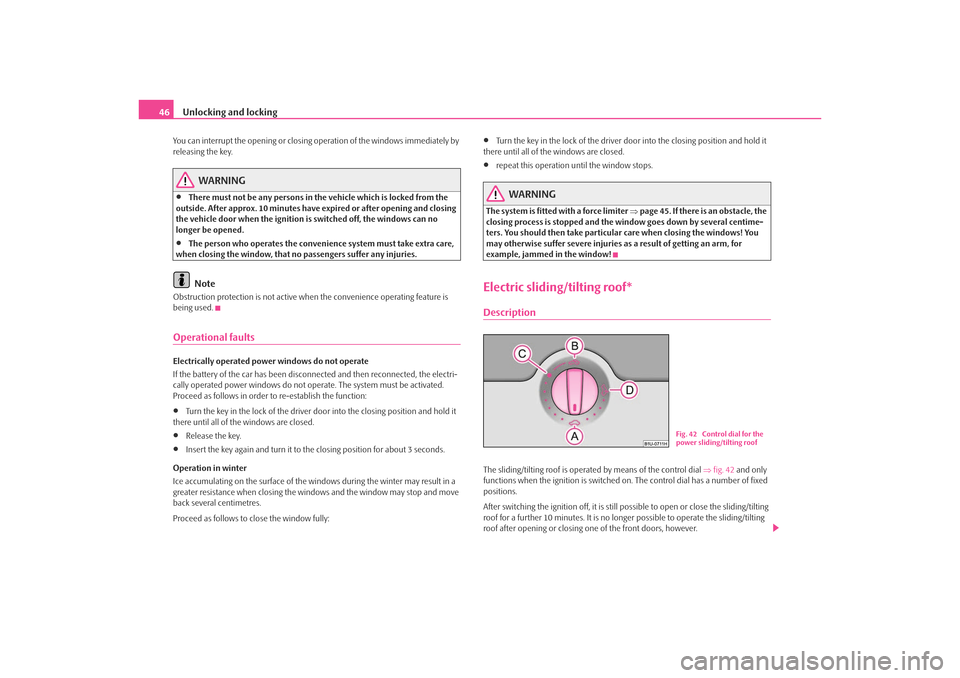
example, jammed in the window!Electric sliding/tilting roof*DescriptionThe sliding/tilting roof is operated by means of the control dial ⇒fig. 42 and only
functions when the ignition is switched on. The control dial has a number of fixed
positions.
After switching the ignition off, it is still possible to open or close the sliding/tilting
roof for a further 10 minutes. It is no longer possible to operate the sliding/tilting
roof after opening or closing one of the front doors, however.
Fig. 42 Control dial for the
power sliding/tilting roof
s2ig.book Page 46 Monday, November 10, 2008 11:20 AM
Page 48 of 226
Unlocking and locking47
Using the system
Safety
Driving Tips
General Maintenance
Breakdown assistance
Technical Data
Note
•
If the battery has been disconnected and reconnected, it is possible that the
sliding/tilting roof does not close fully. He re you have to set the control dial to the
switch position and press it forward for about 10 seconds.
•
It is necessary after each emergency op eration (using crank handle) to move
the sliding/tilting roof into the basic positi on. Here you have to set the control dial
to the switch position and pres s it forward for about 10 seconds.
Opening and tiltingComfort position
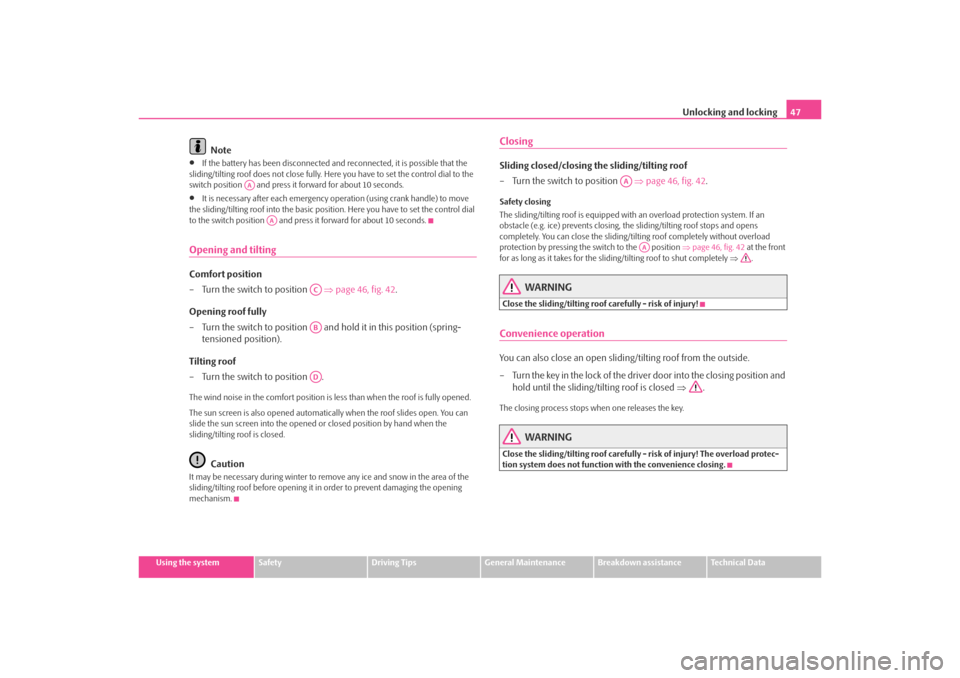
– Turn the switch to position ⇒page 46, fig. 42 .
Opening roof fully
– Turn the switch to position and hold it in this position (spring-
tensioned position).
Tilting roof
– Turn the switch to position .The wind noise in the comfort position is less than when the roof is fully opened.
The sun screen is also opened automatica lly when the roof slides open. You can
slide the sun screen into the opened or closed position by hand when the
sliding/tilting roof is closed.
Caution
It may be necessary during winter to remo ve any ice and snow in the area of the
sliding/tilting roof before opening it in order to prevent damaging the opening
mechanism.
ClosingSliding closed/closing the sliding/tilting roof
– Turn the switch to position ⇒page 46, fig. 42 .Safety closing
The sliding/tilting roof is equipped with an overload protection system. If an
obstacle (e.g. ice) prevents closing, the sliding/tilting roof stops and opens
completely. You can close the sliding/tilting roof completely without overload
protection by pressing the switch to the position ⇒page 46, fig. 42 at the front
for as long as it takes for the sliding/tilting roof to shut completely ⇒.
WARNING
Close the sliding/tilting roof carefully - risk of injury!Convenience operationYou can also close an open sliding/tilting roof from the outside.
– Turn the key in the lock of the driver door into the closing position and
hold until the sliding/tilting roof is closed ⇒.The closing process stops when one releases the key.
WARNING
Close the sliding/tilting roof carefully - risk of injury! The overload protec-
tion system does not function with the convenience closing.
AA
AA
ACABAD
AA
AA
s2ig.book Page 47 Monday, November 10, 2008 11:20 AM
Page 49 of 226
Unlocking and locking
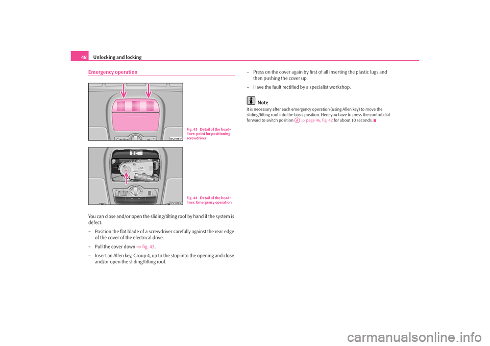
48Emergency operationYou can close and/or open the sliding/ti lting roof by hand if the system is
defect.
– Position the flat blade of a screwdriver carefully against the rear edge of the cover of the electrical drive.
–Pull the cover down ⇒fig. 43 .
– Insert an Allen key, Group 4, up to the stop into the opening and close and/or open the sliding/tilting roof. – Press on the cover again by first of all inserting the plastic lugs and
then pushing the cover up.
– Have the fault rectified by a specialist workshop.
Note
It is necessary after each emergency op eration (using Allen key) to move the
sliding/tilting roof into the basic position . Here you have to press the control dial
forward to switch position ⇒page 46, fig. 42 for about 10 seconds.
Fig. 43 Detail of the head-
liner: point for positioning
screwdriverFig. 44 Detail of the head-
liner: Emergency operation
AA
s2ig.book Page 48 Monday, November 10, 2008 11:20 AM
Page 76 of 226
Seats and Storage75
Using the system
Safety
Driving Tips
General Maintenance
Breakdown assistance
Technical Data
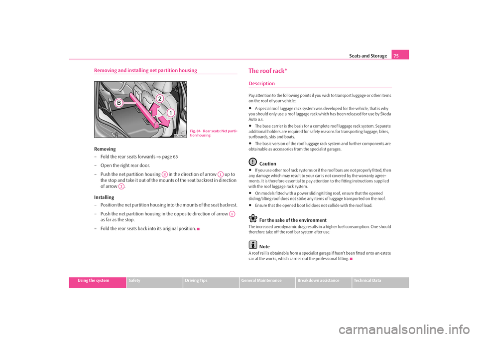
Removing and installing net partition housingRemoving
– Fold the rear seats forwards ⇒page 65
– Open the right rear door.
– Push the net partition housing in the direction of arrow up to the stop and take it out of the mounts of the seat backrest in direction
of arrow .
Installing
– Position the net partition housing in to the mounts of the seat backrest.
– Push the net partition housing in the opposite direction of arrow as far as the stop.
– Fold the rear seats back into its original position.
The roof rack*DescriptionPay attention to the following points if yo u wish to transport luggage or other items
on the roof of your vehicle:•
A special roof luggage rack system was developed for the vehicle, that is why
you should only use a roof luggage rack which has been released for use by Škoda
Auto a.s.
•
The base carrier is the basis for a comple te roof luggage rack system. Separate
additional holders are required for safety reasons for transporting luggage, bikes,
surfboards, skis and boats.
•
The basic version of the roof luggage rack system and further components are
obtainable as accessories from the specialist garages.Caution
•
If you use other roof rack sy stems or if the roof bars are not properly fitted, then
any damage which may result to your ca r is not covered by the warranty agree-
ments. It is therefore essential to pay attention to the fitting instructions supplied
with the roof luggage rack system.
•
On models fitted with a power sliding/tilting roof, ensure that the opened
sliding/tilting roof does not strike any items of luggage transported on the roof.
•
Ensure that the opened boot lid does not collide with the roof load.For the sake of the environment
The increased aerodynamic drag results in a higher fuel consumption. One should
therefore take off the roof bar system after use.
Note
A roof rail is obtainable from a specialist garage if hasn't been fitted onto an estate
car at the works, which carries out the professional fitting.
Fig. 84 Rear seats: Net parti-
tion housing
AB
A1
A2
A1
s2ig.book Page 75 Monday, November 10, 2008 11:20 AM
Page 77 of 226
Seats and Storage
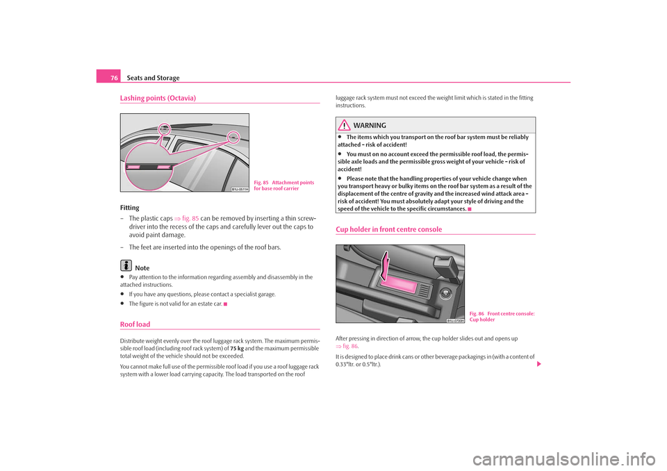
76Lashing points (Octavia)Fitting
– The plastic caps ⇒fig. 85 can be removed by inserting a thin screw-
driver into the recess of the caps and carefully lever out the caps to
avoid paint damage.
– The feet are inserted into the openings of the roof bars.
Note•
Pay attention to the information regarding assembly and disassembly in the
attached instructions.
•
If you have any questions, plea se contact a specialist garage.
•
The figure is not valid for an estate car.
Roof loadDistribute weight evenly over the roof luggage rack system. The maximum permis-
sible roof load (including roof rack system) of 75 kg and the maximum permissible
total weight of the vehicl e should not be exceeded.
You cannot make full use of the permissible roof load if you use a roof luggage rack
system with a lower load carrying capacity. The load transported on the roof luggage rack system must not exceed the weight limit which is stated in the fitting
instructions.
WARNING
•
The items which you transport on the roof bar system must be reliably
attached - risk of accident!
•
You must on no account exceed the permissible roof load, the permis-
sible axle loads and the permissible gros s weight of your vehicle - risk of
accident!
•
Please note that the handling prop erties of your vehicle change when
you transport heavy or bulky items on the roof bar system as a result of the
displacement of the centre of gravity and the increased wind attack area -
risk of accident! You must absolutely adapt your style of driving and the
speed of the vehicle to the specific circumstances.
Cup holder in front centre consoleAfter pressing in direction of arrow, the cup holder slides out and opens up
⇒ fig. 86 .
It is designed to place drink cans or other beverage packagings in (with a content of
0.33°ltr. or 0.5°ltr.).
Fig. 85 Attachment points
for base roof carrier
Fig. 86 Front centre console:
Cup holder
s2ig.book Page 76 Monday, November 10, 2008 11:20 AM