tow SKODA OCTAVIA TOUR 2009 1.G / (1U) Owner's Guide
[x] Cancel search | Manufacturer: SKODA, Model Year: 2009, Model line: OCTAVIA TOUR, Model: SKODA OCTAVIA TOUR 2009 1.G / (1U)Pages: 224, PDF Size: 13.53 MB
Page 145 of 224
Towing a trailer
144
Towing a trailerTo w i n g a t r a i l e rTechnical requirements The towing device must satisfy
certain technical requirements.
Your vehicle is designed primarily for tr
ansporting persons and luggage. It can,
however, also be used for towing a traile
r - provided certain te
chnical equipment is
fitted. If your vehicle has already been supplied with a
factory-fitted
towing device then
everything that is necessary
for towing a trailer in technical terms, and in terms of
the law, has already been taken into account. Your vehicle is fitted with a 13-pin po
wer socket for the electrical connection
between the vehicle and trailer. If th
e trailer which you wish to tow has a
7-pin
connector
, you can use a suitable adapter
5) from Škoda original accessories.
This work must be carried out in accordan
ce with the manufacturer's specifications
if a towing device is retrofitted. Specialist garages are familiar with details
relating to retrofitting a towing device
and for any necessary modifications to the cooling system.
WARNING
We recommend that you have the towing device from Škoda original acces-sories installed by a specialist garage.
He is familiar with all the relevant
details relating to retrofitting such equi
pment. There is a risk of an accident
if the towing device is not properly fitted!
General Maintenance There are a number of points to
pay attention to when towing a
trailer.Trailer load The permissible trailer load must
on no account be exceeded.
You can negotiate appropriatel
y steeper inclines and desc
ents if you do not make
full use of the perm
issible trailer load.
The trailer loads specified only apply for
altitudes
up to 1 000 metres above mean
sea level. The fact that the engine power ou
tput drops with increasing height due to
a lowering of air pressure and thus the abil
ity to climb, means that the towed weight
must be reduced by 10% for every further increase of 1 000 metres in height above sea level. The towed weight is the weight of the (laden) vehicle and the (laden) trailer together. One should take this into account before driving up to higher alti- tudes. The trailer and drawbar load information on the type plate of the towing device are merely test data for the tow
ing device The data relating to your
vehicle, which is often less than this test data, can be found in your vehicle registration documents. Distribution of the load Distribute the load in the trailer in such a way that any heavy items are located as close as possible to the axle. Secure
the items to prevent them slipping.
Tyre inflation pressure Select the tyre inflation pressure on your vehicle for that of “fully laden”, ⇒ page 173. The inflation pressure of the tyres fitted to the trailer adjust in accord- ance with the manufacturer's recommendation. Exterior mirrors You have to have additional
exterior mirrors fitted if you are not able to see the
traffic behind the trailer with the standard rear-view mirrors. Both exterior mirrors
5)In some countries the adapter is
supplied with the towing device.
s2g8.b.book Page 144 Tuesday, April 7, 2009 8:53 AM
Page 146 of 224
Towing a trailer
145
Using the system
Safety
Driving Tips
General Maintenance
Breakdown assistance
Technical Data
should be attached to folding arms. Adjust
the mirrors so that they provide you with
an adequate field of view to the rear. Headlights Before starting off with a hitched trailer, also check the setting of the headlights. Alter the setting as necessary with th
e aid of the headlight beam adjuster
⇒ page 51. Detachable ball head The ball rod is detachable on vehicles which feature a factory-fitted towing device. It is stowed together with separate fitting instructions in the spare wheel well in the luggage compartment of the vehicle. Further information on the towing device
⇒page 146.
Note
•
We recommend that you also have yo
ur vehicle inspected between service
intervals if you tow a trailer frequently.•
The handbrake on the towing vehicle
must be put on when coupling and
decoupling the trailer.Driving Tips Particular caution is required when towing a trailer.– Do not, as far as possible, drive
with your vehicle unladen and the
trailer laden.
– Do not make full use of the legal maximum speeds. This applies in
particular to downhill sections.
– Apply the brakes in good time.– Keep a check on the coolant temper
ature gauge if the outside temper-
ature is high.
Distribution of weight The distribution of the weight is very poor
if your vehicle is
unladen and the trailer
is laden. Maintain a particularly low speed if you cannot avoid driving with this combination. Driving speed Do not drive faster than 80 km/hour for safety reasons. This also applies for coun- tries in which higher speeds are allowed. The fact that the driving stability of the vehicle + trailer combination reduces with increasing speed means that the legally allowed speed should not be used when there are unfavourable road, weather or wind
conditions, particul
arly near accident
black spots. You must always reduce your speed immedi
ately as soon as you detect even just
the
slightest swaying
of the trailer. On no account attempt to stop the trailer from
“swaying” by
accelerating.
Apply the brakes in good time! If the trailer is fitted with a
trailer brake
, apply the
brakes gently at first and then brake firmly
. This will avoid brake jolts resulting from
the trailer wheels locking. Shift down gears
in good time before negotiating a down-
hill section to allow the engine to also act as a brake. Engine overheating Please keep a check on the coolant temperature gauge if you have to negotiate a lengthy slope in a low gear at a high engine speed when the outside temperature is very high
⇒page 16.
If the needle of the coolant temperature gauge moves into the right-hand area or even the red area of the scale, reduce yo
ur speed immediately. Stop and switch off
the engine if the warning light
in the instrument cluste
r begins flashing. Wait a
few minutes and check the level of coolant in the coolant expansion bottle ⇒ page 165, “Inspecting the coolant level”. Please refer to the following guidelines
⇒page 30, “Coolant temperature/ Coolant
quantity
”.
The coolant temperature can be reduced by switching on the heating.Any increase in the cooling effect of the coolant fan through shifting down a gear and increasing the engine speed is not possible since the fan speed is independent
s2g8.b.book Page 145 Tuesday, April 7, 2009 8:53 AM
Page 147 of 224
Towing a trailer
146
of the engine speed. One should also not
drop a gear for this reason when towing
a trailer as long as the en
gine can manage the slope
without any drop in speed.
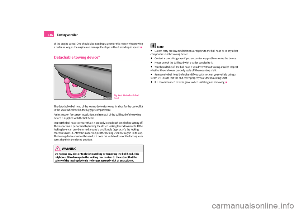
Detachable towing device*The detachable ball head of the towing device
is stowed in a box for the car tool kit
in the spare wheel well in the luggage compartment. An instruction for correct installation an
d removal of the ball head of the towing
device is supplied
with the ball head
Inspect the ball head to ensure that it is pr
operly locked each time before setting off.
The inspection is performed by turning the closed locking lever downwards. If the locking lever can only be turned around a small angle (approx. 5°), the locking mechanism is O.K. After the inspection pull
the locking lever back again to its stop.
The towing device must not be used, if it does not wish to close or the locking lever turns slightly in the closed position.
WARNING
Do not use any aids or tools for installing or removing the ball head. This might result in damage to the locking mechanism to the extent that the safety of the towing device is no longer assured - risk of an accident.
Note
•
Do not carry out any modifications or repairs to the ball head or to any other
components on the towing device.•
Contact a specialist garage if you en
counter any problems using the device.
•
Never unlock the ball head with a trailer coupled to it.
•
You should take off the ball head if you drive without towing a trailer. Inspect
whether the end cover properly seals off the mounting shaft.•
Remove the ball head beforehand if yo
u wish to clean your vehicle using a
steam jet. Ensure that the end cover properly seals the mounting shaft.•
It is recommended to wear gloves
when installing and removing.
Fig. 144 Detachable ball head
s2g8.b.book Page 146 Tuesday, April 7, 2009 8:53 AM
Page 164 of 224
Inspecting and replenishing
163
Using the system
Safety
Driving Tips
General Maintenance
Breakdown assistance
Technical Data
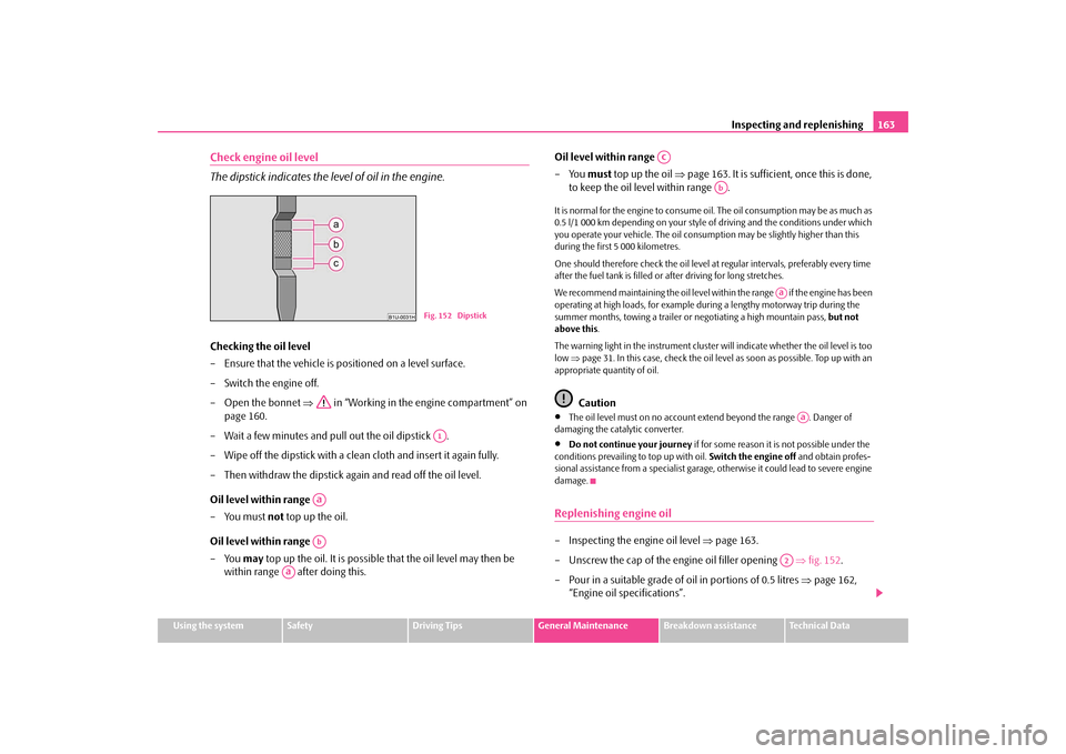
Check engine oil level The dipstick indicates the level of oil in the engine.Checking the oil level – Ensure that the vehicle is positioned on a level surface. – Switch the engine off.– Open the bonnet
⇒
in “Working in the engine compartment” on
page 160.
– Wait a few minutes and pull out the oil dipstick . – Wipe off the dipstick with a clea
n cloth and insert it again fully.
– Then withdraw the dipstick ag
ain and read off the oil level.
Oil level within range – You must
not
top up the oil.
Oil level within range – You
may
top up the oil. It is possible that the oil level may then be
within range after doing this.
Oil level within range –You
must
top up the oil
⇒
page 163. It is sufficient, once this is done,
to keep the oil level within range .
It is normal for the engine to consume oi
l. The oil consumption may be as much as
0.5 l/1 000 km depending on your style of driving and the conditions under which you operate your vehicle. The oil consumpt
ion may be slightly higher than this
during the first 5 000 kilometres. One should therefore check the oil level at regular intervals, preferably every time after the fuel tank is filled or after driving for long stretches. We recommend maintaining the oil level within the range if the engine has been operating at high loads, for example during a lengthy motorway trip during the summer months, towing a trailer or
negotiating a high mountain pass,
but not
above this
.
The warning light in the instrument cluster
will indicate whether the oil level is too
low
⇒page 31. In this case, check the oil level
as soon as possible. Top up with an
appropriate quantity of oil.
Caution
•
The oil level must on no account ex
tend beyond the range . Danger of
damaging the cata
lytic converter.
•
Do not continue your journey
if for some reason it is not possible under the
conditions prev
ailing to top up with oil.
Switch the engine off
and obtain profes-
sional assistance from a specialist garage, otherwise it could lead to severe engine damage.Replenishing engine oil– Inspecting the engine oil level
⇒
page 163.
– Unscrew the cap of the engine oil filler opening
⇒
fig. 152
.
– Pour in a suitable grade of oil in portions of 0.5 litres
⇒
page 162,
“Engine oil specifications”.
Fig. 152 DipstickA1
AaAb
Aa
Ac
Ab
Aa
Aa
A2
s2g8.b.book Page 163 Tuesday, April 7, 2009 8:53 AM
Page 166 of 224
Inspecting and replenishing
165
Using the system
Safety
Driving Tips
General Maintenance
Breakdown assistance
Technical Data
Check hydraulic oil The hydraulic system of the power steering is filled with the hydraulic oil designated in the catalogue as G 002 000. Perform the inspection of the hydraulic oil level when the engine is cold and not running. The hydraulic oil level must be between the “MIN” and “MAX” markings ⇒ page 164, fig. 153
. If the level drops below the mark
ing “MIN”, it is necessary that
the power steering is checked by a specialist
garage. It is not sufficient to solely refill
with hydraulic oil.
Note
If the engine is not running (when towing) or
if the V-ribbed belt is torn, the power
steering does not operate. The vehicle is fully steerable however. There is however increased force required to turn the steering wheel.Cooling systemCoolant The job of the coolant is to cool the engine.The cooling system does not require an
y maintenance under normal operating
conditions. The coolant consists of water
with a concentration of coolant additive
of 40 %. This mixture not only provides
antifreeze protection down to -25°C but
also protects the cooling and heating system from corrosion. It also prevents the formation of scale and significantly increases the boiling point of the coolant. You must therefore not reduce the concentr
ation of antifreeze agent in the coolant
by adding water, also not during the summ
er months or in countries with a warm
climate.
The concentration of coolant additive in the coolant must be at least
40%. You can increase the amount of antifreeze
in the coolant if a higher concentration
of antifreeze is necessary for climatic
reasons but only up to 60% (antifreeze
protection down to approx. -40°C). The an
tifreeze protection tails off above that
concentration.
Vehicles exported to countries with a co
ld climate (e.g. Sweden, Norway, Finland)
are already factory-filled with a coolant which offers antifreeze protection down to about -35°C. In these countries the concentr
ation of coolant additive should be at
least 50 %. Coolant The cooling system is factory-filled with
coolant (purple in colour), which complies
with the specification TL-VW 774 G. We recommend that you use the same c
oolant additive - G12 PLUS-PLUS (purple
in colour) for topping up the system. Please contact a specialist garage if you have any questions regarding the coolant or if you wish to fill up with a different coolant. A specialist garage can also supply
you with the correct coolant additives.
Caution
•
Other coolant additives may cause operational problems which, in partic-
ular, involves significantly reducing the anticorrosion effect.•
Any faults or problems resulting from corrosion may cause a loss of
coolant and, as a consequence of th
is, result in major engine damage.
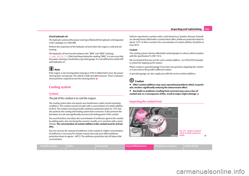
Inspecting the coolant level
Fig. 154 Engine compart- ment: Coolant expansion bottle
s2g8.b.book Page 165 Tuesday, April 7, 2009 8:53 AM
Page 182 of 224
Breakdown assistance
181
Using the system
Safety
Driving Tips
General Maintenance
Breakdown assistance
Technical Data
Breakdown assistanceBreakdown assistanceFirst-aid box*, Warning triangle* and bulb set*A space for stowing the first-aid box and the bulb set is located in a well of the plastic part under th
e floor covering of the luggage compartment behind the spare
wheel. A space for the warning triangle is located in the luggage compartment.
Note
•
Pay attention to the use-by-date of the contents of the first-aid box.
•
If you equip your vehi
cle additionally with a warning
triangle or with a first-aid
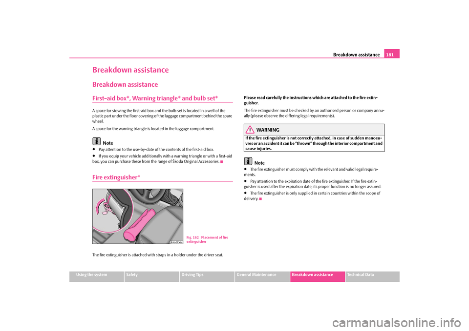
box, you can purchase these from the range of Škoda Original Accessories.Fire extinguisher*The fire extinguisher is attached with st
raps in a holder under the driver seat.
Please read carefully the
instructions which are atta
ched to the fire extin-
guisher. The fire extinguisher must be checked by an authorised person or company annu- ally (please observe the differing legal requirements).
WARNING
If the fire extinguisher
is not correctly attached,
in case of sudden manoeu-
vres or an accident it can be “thrown” through the interior compartment and cause injuries.
Note
•
The fire extinguisher must comply with
the relevant and valid legal require-
ments.•
Pay attention to the expiration date of the fire extinguisher. If the fire extin-
guisher is used after the expiration date,
its proper function is
no longer assured.
•
The fire extinguisher is only supplied in certain countries within the scope of
delivery.
Fig. 162 Placement of fire extinguisher
s2g8.b.book Page 181 Tuesday, April 7, 2009 8:53 AM
Page 183 of 224
Breakdown assistance
182
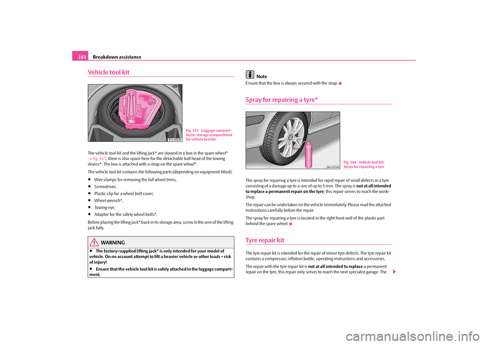
Vehicle tool kitThe vehicle tool kit and the lifting jack* are stowed in a box in the spare wheel* ⇒ fig. 163
; there is also space here for the de
tachable ball head of the towing
device*. The box is attached with a strap on the spare wheel*. The vehicle tool kit contains the following parts (depending on equipment fitted):•
Wire clamps for removing
the full wheel trims,
•
Screwdriver,
•
Plastic clip for a wheel bolt cover,
•
Wheel wrench*,
•
Towing eye,
•
Adapter for the safety wheel bolts*.
Before placing the lifting jack* back in its
storage area, screw in the arm of the lifting
jack fully.
WARNING
•
The factory-supplied lifting jack* is
only intended for your model of
vehicle. On no account attempt to lift
a heavier vehicle or other loads - risk
of injury!•
Ensure that the vehicle tool kit is safely attached in the luggage compart-
ment.
Note
Ensure that the box is alwa
ys secured with the strap.
Spray for repairing a tyre*The spray for repairing a tyre is intended fo
r rapid repair of small defects in a tyre
consisting of a damage up to a si
ze of up to 5 mm. The spray is
not at all intended
to replace a permanent repair on the tyre
; this repair serves to reach the work-
shop. The repair can be undertaken on the vehicl
e immediately. Please read the attached
instructions carefully before the repair. The spray for repairing a tyre is located in
the right front well of the plastic part
behind the spare wheel.Tyre repair kitThe tyre repair kit is intended for the repair of minor tyre defects. The tyre repair kit contains a compressor, inflation bottle, operating instructions and accessories. The repair with the
tyre repair kit is
not at all intended to replace
a permanent
repair on the tyre, this repair only serves
to reach the next specialist garage. The
Fig. 163 Luggage compart- ment: storage compartment for vehicle tool kit
Fig. 164 Vehicle tool kit: Spray for repairing a tyre
s2g8.b.book Page 182 Tuesday, April 7, 2009 8:53 AM
Page 185 of 224
Breakdown assistance
184
prescribed distance from your vehicl
e while observing all national legal
provisions. In this way you are protecting not only yourself but also other road users.•
Never start the engine with the vehicle
sitting on the raised jack - danger
of suffering injury.
Caution
If you have to change a wheel on a slope
first block the opposite wheel with a stone
or similar object in order to secure th
e vehicle from unexpectedly rolling away.
Note
Comply with the national legal regulations.Changing a wheelAlways change a wheel on a level surface as far as possible. – Take off the full wheel trim*
⇒
page 185 or the caps
⇒
page 185.
– In the case of light alloy wheels remove the wheel trim cap
⇒
page 186.
– Slacken the wheel bolts
⇒
page 186.
– Jack up the vehicle until the wheel to
be changed is clear of the ground
⇒
page 187.
– Unscrew the wheel bolts and place them on a clean surface (cloth,
paper etc.).
– Take off the wheel.– Fit on the new spare wheel* and tighten the wheel bolts slightly. –Lower the car.
– Tighten the wheel bolts firmly, al
ternately and diagonally using the
wrench* (crosswise)
⇒
page 186.
– Mount the full wheel trim/w
heel trim cap or the caps.
Note
•
All bolts must be clean
and must turn easily.
•
You must never grease or oil the wheel bolts!
•
When fitting on unidirectional tyres, ensure that the tyres rotate in the correct
direction
⇒page 173.
Subsequent stepsAfter changing the wheel, you must perform the following steps. – Stow and attach the replaced wheel in the spare wheel well. – Stow the vehicle tool kit in the space provided.–
Check
the
tyre pressure
on the spare wheel* just mounted as soon
as possible.
– Have the
tightening torque
of the wheel bolts
checked
with a torque
wrench as soon as possible. Steel and light alloy wheels must be tight-ened to a tightening torque of
120 Nm
.
– Have the defective tyre repaired as soon as possible.
WARNING
It is necessary to observe the guidelines given on
⇒page 175, “New tyres
and wheels” if the vehicle is subseq
uently fitted with tyres which are
different to those it was fitted with at the works.
WARNING (continued)
s2g8.b.book Page 184 Tuesday, April 7, 2009 8:53 AM
Page 190 of 224
Breakdown assistance
189
Using the system
Safety
Driving Tips
General Maintenance
Breakdown assistance
Technical Data
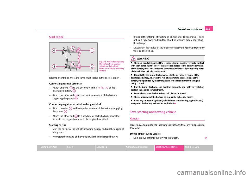
Start engineIt is important to connect the jump
-start cables in the correct order.
Connecting positive terminals – Attach one end to the positive terminal
⇒
fig. 172
of the
discharged battery .
– Attach the other end to the positive terminal of the battery
supplying the power .
Connecting negative term
inal and engine block
– Attach one end to the negative
terminal of the battery supplying
the power .
– Attach the other end to a solid metal part which is connected
firmly to the engine block, or
to the engine block itself.
Starting engine – Start the engine of the vehicle providing current and run the engine at
idling speed.
– Now start the engine of the vehicle with the discharged battery.
– Interrupt the attempt at starting an engine after 10 seconds if it does
not start right away and wait for about 30 seconds before repeating the attempt.
– Disconnect the cables on the engine in exactly the
reverse order
they
were connected up.
WARNING
•
The non-insulated parts of the terminal clamps must never make contact
with each other. Furthermore, the cable connected to the positive terminal of the battery must not come into contact with electrically conducting parts of the vehicle - risk of a short circuit!•
Do not affix the jump starting cables to the negative terminal of the
discharged battery. There is the risk
of detonating gas seeping out the
battery being ignited by the strong
spark which results from the engine
being started.•
Run the jump-start cables so that th
ey cannot be caught
by any rotating
parts in the engine compartment.•
Do not bend over the batteries - risk of caustic burns!
•
The vent screws of the battery cells must be tightened firmly.
•
Keep any sources of ignition (naked
flame, smouldering cigarettes etc.)
away from the battery - risk of an explosion!Tow-starting and towing vehicleGeneralPlease pay attention to the following in
structions if you are going to use a
tow rope: Driver of the towing vehicle – Do not drive off until the tow rope is taught.
Fig. 172 Jump-starting using the battery from another vehicle: A - flat vehicle battery, B - battery providing current
A1AAA2AB
A3
AB
A4
s2g8.b.book Page 189 Tuesday, April 7, 2009 8:53 AM
Page 191 of 224
Breakdown assistance
190
– Release the clutch particular
ly gently when starting off.
Driver of the towed vehicle – Switch the ignition on so that the steering wheel is not blocked and
you can also operate the turn signal
lights, the headlight flasher, the
windscreen wipers and wi
ndscreen washer system.
– Take the vehicle out of gear. – Note that the brake servo unit and power steering only operate if the
engine is running. You will require si
gnificantly greater physical force
to depress the brake pedal and to steer the vehicle if the engine is not running.
– Ensure that the tow rope is always kept taught.Tow rope or tow bar A tow
bar
is safest way of towing a vehicle and also minimizes any shocks. You can
use a tow
rope
only if a suitable tow bar is not available.
The tow rope must be elastic to protect
the vehicle. Thus one should only use
plastic fibre rope or a rope made
out of a similarly elastic material.
Only attach the tow rope to the
towing eyes
provided for this purpose
⇒page 190,
“Front towing eye”. Driving style Towing another vehicle requires a certain
amount of practice. Both drivers should
be familiar with the particular points
about towing a vehicle. Unskilled drivers
should not attempt to tow in another vehicle or to be towed in. One should be constantly vigilant not to allow impermissibly high towing forces or jerky loadings. There is always a risk of excessive stresses and damage resulting at the points to which you attach the tow ro
pe or tow bar when you attempt to tow a
vehicle which is not standing on a paved road.
Caution
If the gearbox of your vehicle no longer
contains any oil because of a defect, your
vehicle must only be towed in with the driven wheels raised clear of the ground, or on a special vehicle transporter or trailer.
Note
•
Please comply with any legal requirements particularly regarding the switched
on signal systems, when towing in
or tow-starting another vehicle.
•
The tow rope must not be twisted as it may in certain circumstances result in the
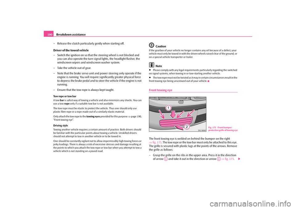
front towing eye being unscrewed out of your vehicle.Front towing eyeThe front towing eye is welded on behind the bumper on the right ⇒
fig. 173
. The tow rope or the tow bar must only be attached to this eye.
The grille is secured with plastic lugs at the points of the arrows. Remove the grille as follows: – Grasp the grille on the ribs in the upper area. Press it in the direction
of arrow and take it out in the direction or arrow
⇒
fig. 173
.
Fig. 173 Front bumper: protective grille of towing eye
A1
A2
s2g8.b.book Page 190 Tuesday, April 7, 2009 8:53 AM