fuse SKODA OCTAVIA TOUR 2009 1.G / (1U) Owner's Manual
[x] Cancel search | Manufacturer: SKODA, Model Year: 2009, Model line: OCTAVIA TOUR, Model: SKODA OCTAVIA TOUR 2009 1.G / (1U)Pages: 224, PDF Size: 13.53 MB
Page 5 of 224
Contents
4Driving Tips
. . . . . . . . . . . . . . . . . . . . . . . . . . . . . .
Intelligent Technology
. . . . . . . . . . . . . . . . . . . . . . . .
Electronic stability programme (ESP)* . . . . . . . . . . Brakes . . . . . . . . . . . . . . . . . . . . . . . . . . . . . . . . . . . . . . . Brake booster . . . . . . . . . . . . . . . . . . . . . . . . . . . . . . . . Antilock brake system (ABS)* . . . . . . . . . . . . . . . . . . Brake Assist* . . . . . . . . . . . . . . . . . . . . . . . . . . . . . . . . . Driving and the Environment
. . . . . . . . . . . . . . . . .
The first 1 500 kilometres and then afterwards . . Catalytic converter . . . . . . . . . . . . . . . . . . . . . . . . . . . . Driving in an economical and environmentally conscious manner . . . . . . . . . . . . . . . . . . . . . . . . . . . . Environmental compatibility . . . . . . . . . . . . . . . . . . . Motoring abroad . . . . . . . . . . . . . . . . . . . . . . . . . . . . . Avoiding damage to your vehicle . . . . . . . . . . . . . . To w i n g a t r a i l e r
. . . . . . . . . . . . . . . . . . . . . . . . . . . . . . . .
Towing a trailer . . . . . . . . . . . . . . . . . . . . . . . . . . . . . . . Detachable towing device* . . . . . . . . . . . . . . . . . . . . General Maintenance
. . . . . . . . . . . . . . .
Taking care of your ve
hicle and cleaning the
vehicle
. . . . . . . . . . . . . . . . . . . . . . . . . . . . . . . . . . . . . . . . .
General . . . . . . . . . . . . . . . . . . . . . . . . . . . . . . . . . . . . . . Care of the exterior of vehicle . . . . . . . . . . . . . . . . . . Care of the interior of vehicle . . . . . . . . . . . . . . . . . . Fuel
. . . . . . . . . . . . . . . . . . . . . . . . . . . . . . . . . . . . . . . . . . . . Petrol . . . . . . . . . . . . . . . . . . . . . . . . . . . . . . . . . . . . . . . . Diesel . . . . . . . . . . . . . . . . . . . . . . . . . . . . . . . . . . . . . . . Refuelling . . . . . . . . . . . . . . . . . . . . . . . . . . . . . . . . . . . . Emergency release of fuel filler flap . . . . . . . . . . . . Inspecting and replenishing
. . . . . . . . . . . . . . . . . .
Engine compartment . . . . . . . . . . . . . . . . . . . . . . . . . Engine oil . . . . . . . . . . . . . . . . . . . . . . . . . . . . . . . . . . . . Cooling system . . . . . . . . . . . . . . . . . . . . . . . . . . . . . . . Brake fluid . . . . . . . . . . . . . . . . . . . . . . . . . . . . . . . . . . .
Battery . . . . . . . . . . . . . . . . . . . . . . . . . . . . . . . . . . . . . . . Windshield washer system . . . . . . . . . . . . . . . . . . . .Wheels and Tyres
. . . . . . . . . . . . . . . . . . . . . . . . . . . . . .
Wheels . . . . . . . . . . . . . . . . . . . . . . . . . . . . . . . . . . . . . .Accessories, changes and replacement of partsAccessories and replacement parts . . . . . . . . . . . . . Technical changes . . . . . . . . . . . . . . . . . . . . . . . . . . . .Vehicles of the group N1 . . . . . . . . . . . . . . . . . . . . . .Breakdown assistance
. . . . . . . . . . . . . .
Breakdown assistance
. . . . . . . . . . . . . . . . . . . . . . . .
First-aid box*, Warning triangle* and bulb set* . . Fire extinguisher* . . . . . . . . . . . . . . . . . . . . . . . . . . . . .Vehicle tool kit . . . . . . . . . . . . . . . . . . . . . . . . . . . . . . . .Spray for repairing a tyre* . . . . . . . . . . . . . . . . . . . . .Tyre repair kit . . . . . . . . . . . . . . . . . . . . . . . . . . . . . . . . .Spare wheel* . . . . . . . . . . . . . . . . . . . . . . . . . . . . . . . . .Changing a wheel . . . . . . . . . . . . . . . . . . . . . . . . . . . . .Jump-starting . . . . . . . . . . . . . . . . . . . . . . . . . . . . . . . .Tow-starting and towing vehicle . . . . . . . . . . . . . . .Fuses and light bulbs
. . . . . . . . . . . . . . . . . . . . . . . . . .
Electric fuses . . . . . . . . . . . . . . . . . . . . . . . . . . . . . . . . . Bulbs . . . . . . . . . . . . . . . . . . . . . . . . . . . . . . . . . . . . . . . .Technical Data
. . . . . . . . . . . . . . . . . . . . . . . . . .
Technical Data
. . . . . . . . . . . . . . . . . . . . . . . . . . . . . . . . .
General information . . . . . . . . . . . . . . . . . . . . . . . . . . Used abbreviations . . . . . . . . . . . . . . . . . . . . . . . . . . .Performances . . . . . . . . . . . . . . . . . . . . . . . . . . . . . . . .Weight . . . . . . . . . . . . . . . . . . . . . . . . . . . . . . . . . . . . . . .Identification details . . . . . . . . . . . . . . . . . . . . . . . . . .Fuel consumption according to the regulations (99/100/EU) . . . . . . . . . . . . . . . . . . . . . . . . . . . . . . . . . . Dimensions . . . . . . . . . . . . . . . . . . . . . . . . . . . . . . . . . .1.4 ltr./55 kW - EU4 . . . . . . . . . . . . . . . . . . . . . . . . . . .1.6 ltr./75 kW - EU4/EU2 DDK . . . . . . . . . . . . . . . . . .
1.8 ltr./110 kW - EU4/EU3D . . . . . . . . . . . . . . . . . . . . 1.9 ltr./66 kW TDI - EU3 . . . . . . . . . . . . . . . . . . . . . . . .1.9 ltr./74 kW TDI PD - EU4 . . . . . . . . . . . . . . . . . . . .Octavia - Vehicles of the group N1 . . . . . . . . . . . . . .Octavia Combi - Vehicles of the group N1 . . . . . . .Index
. . . . . . . . . . . . . . . . . . . . . . . . . . . . . . . . . . . . . . . .
131 131 131 133134135135 137 137 138 138 142142143 144 144 146 147 147 147 147152 155 155 155156157 159 159 162165167
168 172 173 173 179 179 179179 181 181 181 181182182182183183188189 192 192 195 201 201 201 201201201201 202 203204206
208 210 212214214 215
s2g8.b.book Page 4 Tuesday, April 7, 2009 8:53 AM
Page 32 of 224
Instruments and Indicator/Warning Lights
31
Using the system
Safety
Driving Tips
General Maintenance
Breakdown assistance
Technical Data
obtain professional assistance from a specialist garage, otherwise it could lead to severe engine damage. If the coolant is within the specified
range, the increased temperature may be
caused by an operating problem at the coolant fan. Check the fuse for the coolant fan, replace it if necessary
⇒page 193, “Fuse assignment in engine compartment -
version 1” or
⇒page 194, “Fuse assignment in en
gine compartment - version 2”.
Do not continue driving
if the warning light does not go
off although the fluid is at
the correct level and also the fuse of the fa
n is in proper order. Contact a specialist
garage to obtain assistance. Please also refer to the additional instructions
⇒page 165, “Cooling system”.
The following text will be displayed in the information display*:
STOP CHECK COOLANT SERVICE MANUAL
WARNING
•
If you must stop for technical reasons, then park the vehicle at a safe
distance from the traffic
and switch off the engine and switch on the hazard
warning light system
⇒page 52.
•
Take care when opening the coolant expa
nsion bottle. If the engine is hot,
the cooling system is pressurized - risk of scalding! It is best to allow the engine to cool down before removing the cap.•
Do not touch the coolant fan The coolant fan may switch on automati-
cally even if the ignition is off.Thickness of the brake pads*
The warning light
comes on for a few seconds when the ignition is switched on.
If the warning light
comes on, contact a specialist garage immediately and have
the brake pads on
all of the wheels
inspected.
A peep sounds as an addi
tional warning signal.
The following text will be displayed in the information display*:
CHECK BRAKE PADS
Windshield washer fluid level*
The warning light
comes on when the ignition is
switched on if there is insuffi-
cient fluid in the windshield washer system. Top up with liquid
⇒page 172.
A peep sounds as an additional warning signal.The following text will be displayed in the information display*:
TOP UP WASH FLUID
Fuel reserve
The warning light
comes on, if the fuel level is still below 7 litres.
A peep sounds as an additional warning signal.The following text will be displayed in the information display*:
PLEASE REFUELNote
The Text in the information display* goes out only after refuelling and driving a short distance.Engine oil
The warning light
lights up red (low oil pressure)
The warning light comes on for a few seconds when the ignition is switched on
3).
Stop the vehicle and sw
itch the engine off
if the warning light does not go off
within a few seconds after switching on the ignition or flashes while driving. Check the oil level and top up with oil as necessary
⇒page 163.
3 peeps sound as an additional warning signal.3)The warning light
on vehicles fitted with information display does not come on after
switching the ignition on, but only if a fault exists or the engine oil level is too low.
s2g8.b.book Page 31 Tuesday, April 7, 2009 8:53 AM
Page 50 of 224
Lights and Visibility
49
Using the system
Safety
Driving Tips
General Maintenance
Breakdown assistance
Technical Data
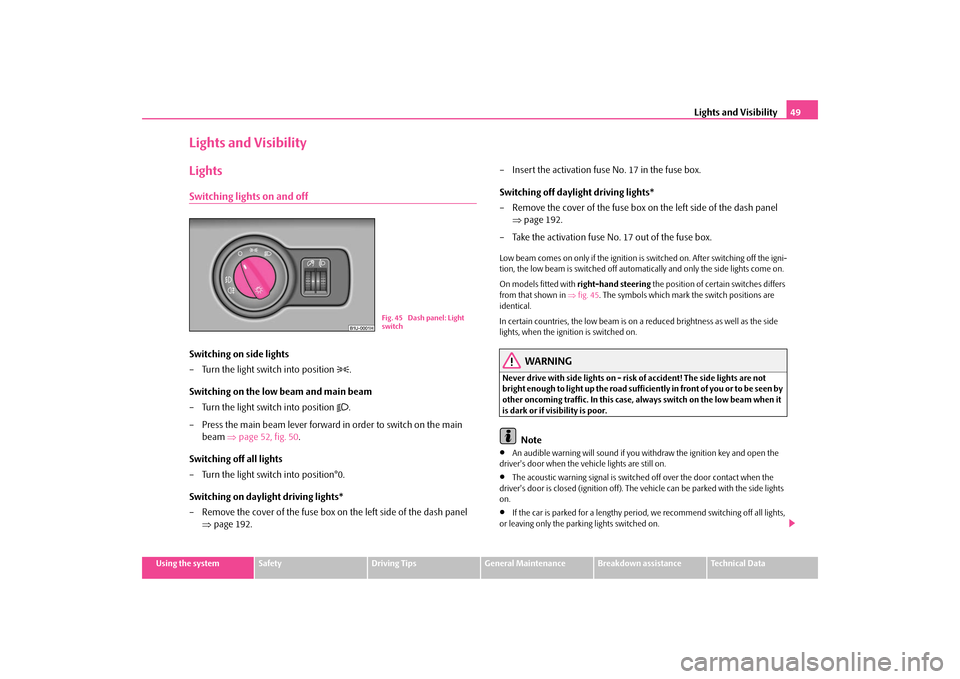
Lights and VisibilityLightsSwitching lights on and offSwitching on side lights – Turn the light switch into position
.
Switching on the low beam and main beam – Turn the light switch into position
.
– Press the main beam lever forward in order to switch on the main
beam
⇒
page 52, fig. 50
.
Switching off all lights – Turn the light switch into position°0. Switching on daylight driving lights* – Remove the cover of the fuse box on the left side of the dash panel
⇒
page 192.
– Insert the activation fuse No. 17 in the fuse box. Switching off daylight driving lights* – Remove the cover of the fuse box on
the left side of the dash panel
⇒
page 192.
– Take the activation fuse No. 17 out of the fuse box.Low beam comes on only if the ignition is
switched on. After switching off the igni-
tion, the low beam is switched off automati
cally and only the side lights come on.
On models fitted with
right-hand steering
the position of certain switches differs
from that shown in
⇒fig. 45
. The symbols which mark the switch positions are
identical. In certain countries, the low beam is on a
reduced brightness as well as the side
lights, when the ignition is switched on.
WARNING
Never drive with side lights on - risk of accident! The side lights are not bright enough to light up the road suffic
iently in front of you or to be seen by
other oncoming traffic. In this case, always switch on the low beam when it is dark or if visibility is poor.
Note
•
An audible warning will sound if you wi
thdraw the ignition key and open the
driver's door when the vehicle lights are still on.•
The acoustic warning signal is switched off over the door contact when the
driver's door is closed (ignition off). The
vehicle can be parked
with the side lights
on.•
If the car is parked for a lengthy period
, we recommend switching off all lights,
or leaving only the parking lights switched on.
Fig. 45 Dash panel: Light switch
s2g8.b.book Page 49 Tuesday, April 7, 2009 8:53 AM
Page 93 of 224
Heating and air conditioning system
92
Note
If the windscreen mists up, press the button
⇒page 90, fig. 102
. After the
windscreen has been demisted, press the button .Setting temperatureYou can set the interior temperature randomly with the buttons and
.
You can set the interior temperature between +18°C (64°F) and +29°C (84 °F). The interior temperature is regulated automatica
lly within this range. If you select the
temperature below +18°C (64 °F), “LO” appe
ars in the display. If you select the
temperature higher than +29°C (84 °F), “H
I” appears in the display. In both limit
positions the Climatronic operates at
maximum cooling or heating capacity,
respectively. The temperature is not controlled in this case. Lengthy and uneven distribution of the air flow out of the vents (in particular at the leg area) and large differences in temperature, for example when getting out of the vehicle, can result in chills in sensitive persons.Controlling blower There are a total of six blower stages available.The Climatronic system controls the bl
ower stages automatically in line
with the interior temperature. You
can also, however, adapt the blower
stages manually to suit
your particular needs.
– Press the button or
⇒
page 90, fig. 102
in order to decrease or
increase the speed.
If you switch off the blowers, th
e Climatronic is switched off and
OFF
is shown in
the display. The set blower speed is indicated by the lighting up of the respective number of bars at the point .
WARNING
•
“Stale air” may result in fatigue in
the driver and occupants, reduce
attention levels and also cause the windows to mist up. The risk of having an accident increases.•
Do not switch the Climatronic syst
em off for longer than necessary.
•
Switch the Climatronic system on as soon as the windows mist up.
Operational problemsIf all the symbols on the display of the au
tomatic air conditioning system flash for
approx. 15 seconds after switching on the ignition, then there is a fault in the system - visit a specialist garage. If the cooling system does not oper
ate, the following faults may exist:
•
the outside temperature is lower than +5°C,
•
The compressor of the automatic air
conditioning system was temporarily
switched off due to a too high temperature of the coolant,•
a blown fuse.
Check the fuse, replace it if necessary
⇒page 192. If a blown fuse is not the source
of the fault, switch the Climatronic off and have it checked. If the cooling capacity decreases, switch
the Climatronic off and have it checked.
A1AUTO
A15
A16
A11
A12
A2
s2g8.b.book Page 92 Tuesday, April 7, 2009 8:53 AM
Page 96 of 224
Starting-off and Driving
95
Using the system
Safety
Driving Tips
General Maintenance
Breakdown assistance
Technical Data
•
Let go of the key as soon as the engine starts otherwise there may be damage
to the starter. The engine running noises may louder at
first be louder for
a short time after
starting the cold engine until oil pressure
can be built up in the hydraulic valve
clearance compensation. This is quite normal and is not an operating problem. If the engine does not start ... You can use the battery of anothe
r vehicle as a jump-start aid
⇒page 188.
It is only possible to tow-start vehicl
es fitted with a manual gearbox. The tow-
starting distance must not be more than 50 metres
⇒page 191.
WARNING
•
Never run the engine in non ventilat
ed or enclosed areas. The exhaust
gases of the engine contain besides
the odorless and colourless carbon
monoxide a poisonous gas - hazard! Carbon monoxide can cause uncon- sciousness and death.•
Never leave your vehicle unattended with the engine running.Caution
•
The starter may only be operated (ignition key position ), if the engine is not
running. If the starter is immediately oper
ated after switching off the engine, the
starter or the engine can be damaged.•
Avoid high engine revolutions, full throttle and high engine loads as long as the
engine has not yet reached its normal oper
ating temperature - risk of damaging the
engine!•
Vehicles which are fitted wi
th an exhaust gas catalyti
c converter should not be
tow-started over a distance of more than 50 metres.
For the sake of the environment
Never warm up the engine when the vehi
cle is standing. Drive off right away.
Through this the engine reaches its operating temperature more rapidly and the pollutant emissions are lower.
Petrol enginesThese engines are fitted with a starter system which selects the correct fuel-air mixture for every external air temperature.•
Do
not depress
accelerator before and when starting engine.
•
Interrupt the attempt at starting after
10 seconds if the engine does not start
right awayand wait for about 30 se
conds before repeating the attempt.
•
It is possible that the fuse on the electric
al fuel pump is defect if the engine still
does not start. Check the fuse and replace it if necessary
⇒page 192.
•
Contact the nearest specialist garage to obtain professional assistance.
It may be necessary, if the engine is
very hot
, to slightly depress the accelerator
after the engine has started.Diesel enginesGlow plug system Diesel engines are equipped with a glow
plug system, the preglow period being
controlled automatically in
line with the coolant temperature and outside temper-
ature. The preglow indicator light
comes on after the ignition has been switched on.
You should not switch on any major electrical components during the heating period otherwise the vehicle battery will be drained unnecessarily.•
You should start the engine immediately after the glow plug warning light
has gone out.•
The glow plug warning light will come on for about one second if the engine is
at a normal operating temperature or if the outside temperature is above +5°C. This means that you can start the engine
right away
.
•
Interrupt the attempt at starting after
10 seconds if the engine does not start
right awayand wait for about 30 se
conds before repeating the attempt.
•
It is possible that the fuse on the diesel preglow system is defect if the engine
still does not start. Check the fuse and replace it if necessary
⇒page 192.
•
Contact the nearest specialist garage to obtain professional assistance.
A3
s2g8.b.book Page 95 Tuesday, April 7, 2009 8:53 AM
Page 193 of 224
Fuses and light bulbs
192
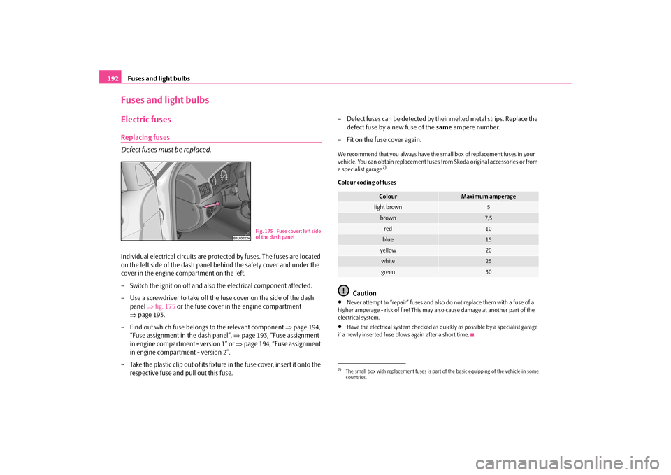
Fuses and light bulbsElectric fusesReplacing fuses Defect fuses must be replaced.Individual electrical circuits are prot
ected by fuses. The fuses are located
on the left side of the dash panel behind the safety cover and under the cover in the engine compartment on the left. – Switch the ignition off and also the electrical component affected.– Use a screwdriver to take off the fuse cover on the side of the dash
panel
⇒
fig. 175
or the fuse cover in the engine compartment
⇒
page 193.
– Find out which fuse belongs to the relevant component
⇒
page 194,
“Fuse assignment in the dash panel”,
⇒
page 193, “Fuse assignment
in engine compartment - version 1” or
⇒
page 194, “Fuse assignment
in engine compartment - version 2”.
– Take the plastic clip out of its fixture in the fuse cover, insert it onto the
respective fuse and pull out this fuse.
– Defect fuses can be detected by th
eir melted metal st
rips. Replace the
defect fuse by a new fuse of the
same
ampere number.
– Fit on the fuse cover again.We recommend that you always have the
small box of replacement fuses in your
vehicle. You can obtain replacement fuses from Škoda original accessories or from a specialist garage
7).
Colour coding of fuses
Caution
•
Never attempt to “repair” fuses and also do not replace them with a fuse of a
higher amperage - risk of fire! This may
also cause damage at another part of the
electrical system.•
Have the electrical system checked as quickly as possible by a specialist garage
if a newly inserted fuse blows again after a short time.
Fig. 175 Fuse cover: left side of the dash panel
7)The small box with replacement fuses is part of the basic equipping of the vehicle in somecountries.
Colour
Maximum amperage
light brown
5
brown
7,5
red
10
blue
15
yellow
20
white
25
green
30
s2g8.b.book Page 192 Tuesday, April 7, 2009 8:53 AM
Page 194 of 224
Fuses and light bulbs
193
Using the system
Safety
Driving Tips
General Maintenance
Breakdown assistance
Technical Data
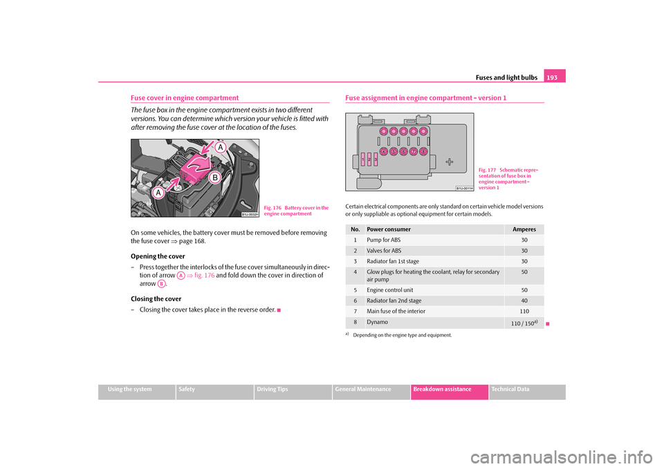
Fuse cover in engine compartment The fuse box in the engine comp
artment exists in two different
versions. You can determine which version your vehicle is fitted with after removing the fuse cover at the location of the fuses.On some vehicles, the battery cover
must be removed before removing
the fuse cover
⇒
page 168.
Opening the cover – Press together the interlocks of th
e fuse cover simultaneously in direc-
tion of arrow
⇒
fig. 176
and fold down the cover in direction of
arrow .
Closing the cover – Closing the cover takes pl
ace in the reverse order.
Fuse assignment in engine compartment - version 1Certain electrical components are only standard on certain vehicle model versions or only suppliable as optional
equipment for certain models.
Fig. 176 Battery cover in the engine compartment
AA
AB
No.
Power consumer
Amperes
1
Pump for ABS
30
2
Valves for ABS
30
3
Radiator fan 1st stage
30
4
Glow plugs for heating the c
oolant, relay for secondary
air pump
50
5
Engine control unit
50
6
Radiator fan 2nd stage
40
7
Main fuse of the interior
110
8
Dynamo
110 / 150
a)
a)Depending on the engine type and equipment.
Fig. 177 Schematic repre- sentation of fuse box in engine compartment - version 1
s2g8.b.book Page 193 Tuesday, April 7, 2009 8:53 AM
Page 195 of 224
Fuses and light bulbs
194
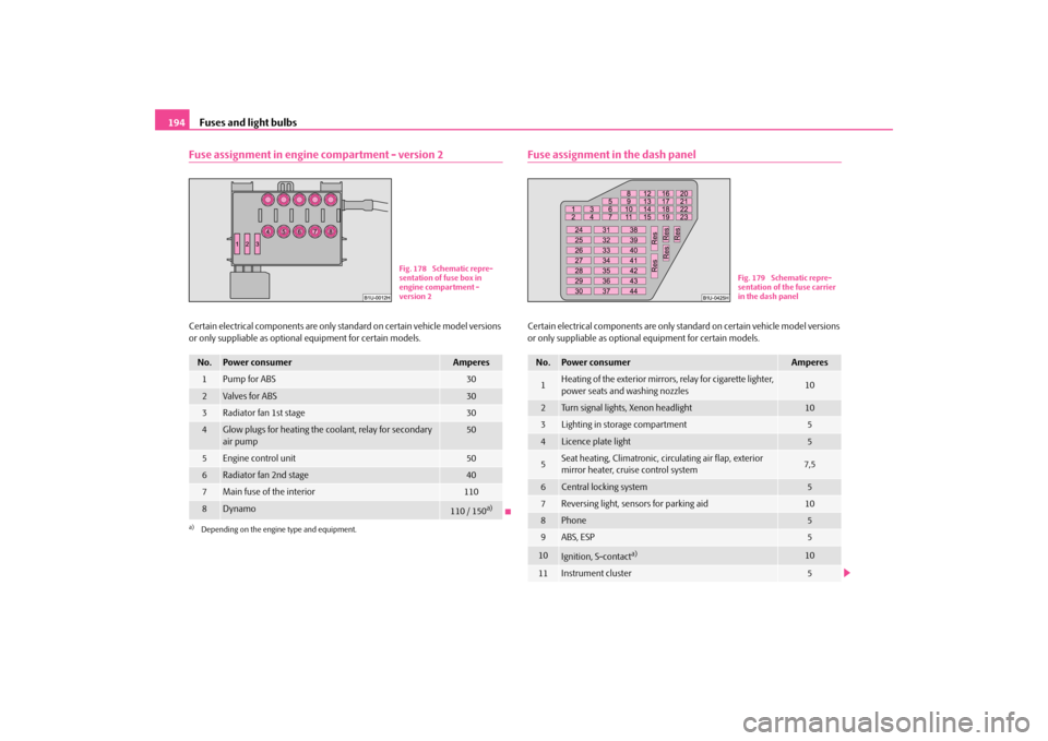
Fuse assignment in engine compartment - version 2Certain electrical components are only st
andard on certain vehicle model versions
or only suppliable as optional
equipment for certain models.
Fuse assignment in the dash panelCertain electrical components are only standard on certain vehicle model versions or only suppliable as optional
equipment for certain models.
No.
Power consumer
Amperes
1
Pump for ABS
30
2
Valves for ABS
30
3
Radiator fan 1st stage
30
4
Glow plugs for heating the coolant, relay for secondary air pump
50
5
Engine control unit
50
6
Radiator fan 2nd stage
40
7
Main fuse of the interior
110
8
Dynamo
110 / 150
a)
a)Depending on the engine type and equipment.
Fig. 178 Schematic repre- sentation of fuse box in engine compartment - version 2
No.
Power consumer
Amperes
1
Heating of the exterior mirrors, relay for cigarette lighter, power seats and washing nozzles
10
2
Turn signal lights, Xenon headlight
10
3
Lighting in storage compartment
5
4
Licence plate light
5
5
Seat heating, Climatronic, circulating air flap, exterior mirror heater, cruise control system
7,5
6
Central locking system
5
7
Reversing light, sensors for parking aid
10
8
Phone
5
9
ABS, ESP
5
10
Ignition, S-contact
a)
10
11
Instrument cluster
5
Fig. 179 Schematic repre- sentation of the fuse carrier in the dash panel
s2g8.b.book Page 194 Tuesday, April 7, 2009 8:53 AM
Page 196 of 224
Fuses and light bulbs
195
Using the system
Safety
Driving Tips
General Maintenance
Breakdown assistance
Technical Data
Electrically adjustable
seats are protected by
automatic circuit breakers
, which
switch on again automatically after a fe
w seconds after the overload has been
eliminated.BulbsChanging bulbsThe relevant lamp must always be switch
ed off before a light bulb is replaced.
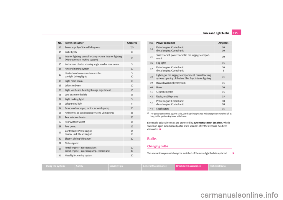
12
Power supply of the self-diagnosis
7,5
13
Brake lights
10
14
Interior lighting, central lockin
g system, interior lighting
(without central locking system)
10
15
Instrument cluster,
steering angle sender, rear mirror
5
16
Air conditioning system
10
17
Heated windscreen washer nozzles daylight driving lights
530
18
Right main beam
10
19
Left main beam
10
20
Right low beam, headlight range adjustment
15
21
Low beam on the left
15
22
Right parking light
5
23
Left parking light
5
24
Front window wiper, motor for wash pump
20
25
Air blower, air conditioning system, Climatronic
25
26
Rear window heater
25
27
Rear window wiper
15
28
Fuel pump
15
29
Control unit: Petrol engine control unit: Diesel engine
1510
30
Electric sliding/tilting roof
20
31
Not assigned
32
Petrol engine - injection valvesdiesel engine - injection pump, control unit
1030
33
Headlight cleaning system
20
No.
Power consumer
Amperes
34
Petrol engine: Control unitdiesel engine: Control unit
1010
35
Trailer socket, power socket in the luggage compart- ment
30
36
Fog lights
15
37
Petrol engine: Control unit diesel engine: Control unit
205
38
Lighting of the luggage compartment, central locking system, opening of the fuel filler flap, interior lighting
15
39
Hazard warning light system
15
40
Horn
20
41
Cigarette lighter
15
42
Radio, mobile phone
15
43
Petrol engine: Control unit diesel engine: Control unit
1010
44
Seat heaters
15
a)For power consumers, e.g. the radio, which can be
operated with the ignition switched off as
long as the ignition key is not withdrawn.No.
Power consumer
Amperes
s2g8.b.book Page 195 Tuesday, April 7, 2009 8:53 AM
Page 197 of 224
Fuses and light bulbs
196
Defect light bulbs should only be replaced with light bulbs of the same type. The designation is located on the light socket or the glass bulb. Changing certain bulbs is not something wh
ich you can do yourself, but requires to
be done by a specialist. Other parts of
the vehicle must be removed in order to
change the light bulbs. This applies, in
particular, to bulbs which can only be
reached from the engine compartment. We therefore recommend that you have any bulbs changed by a specialist garage or, in exceptional cases, by callin
g on other professional assistance.
Please note that the engine compartment is a hazardous area
⇒page 160.
We recommend that you always have a small box of replacement bulbs in your vehicle. You can obtain replacement bulbs from Škoda original accessories or from a specialist garage
8).
A stowage place for the bulbs is located in the box in the spare wheel*.Fitted with a xenon headlightChange of bulbs on vehicles with Xenon li
ghts (low beam lights, parking lights and
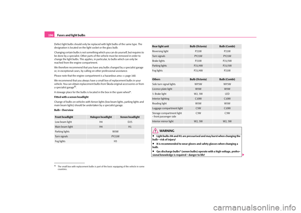
main beam lights) should be undertaken by a specialist garage. Bulb - Overview
WARNING
•
Light bulbs H4 and H1 are pressurise
d and may burst when changing the
bulb - risk of injury!•
It is recommended to wear gloves an
d safety glasses when changing a
bulb.•
Gas discharge bulbs* (xenon bulbs) op
erate with a high voltage, profes-
sional knowledge is requ
ired - danger to life!
8)The small box with replacement bulbs is part of
the basic equipping of the vehicle in some
countries.Front headlight
Halogen headlight
Xenon headlight
Low beam light
H4
D2S
Main beam light
H4
H1
Parking lights
W5W
Turn signals
PY21W
Fog lights
H3
Rear light unit
Bulb (Octavia)
Bulb (Combi)
Reversing light
P21W
P21W
Tu r n s i g n a l s
PY21W
PY21W
Brake lights
P21W
P21/5W
Parking lights
P21/4W
P21/5W
Fog lights
P21/4W
P21W
Others
Bulb (Octavia)
Bulb (Combi)
Side turn signal lights
WY5W
WY5W
Licence plate light
W5W
W5W
3. Brake light
W2, 3W
LED
Interior lighting
C10W
C10W
Reading light
W5W
W5W
Luggage compartment light
C5W
C10W
Storage compartment light - front passenger side
C3W
C3W
Interior mirror light
W2, 3W
W2, 3W
s2g8.b.book Page 196 Tuesday, April 7, 2009 8:53 AM