instrument cluster SKODA OCTAVIA TOUR 2010 1.G / (1U) Columbus Navigation System Manual
[x] Cancel search | Manufacturer: SKODA, Model Year: 2010, Model line: OCTAVIA TOUR, Model: SKODA OCTAVIA TOUR 2010 1.G / (1U)Pages: 207, PDF Size: 12.63 MB
Page 31 of 207
Instruments and warning lights
30
In this case have the engine inspected without delay by a specialist garage.
The following text will be displayed in the information display*:
OIL SENSOR WORKSHOP!
WARNING
If you must stop for technical reasons, then park the vehicle at a safe
distance from the traffic and switch off the engine and switch on the hazard
warning light system page 48.
The red oil pressure light
is not an oil level indicator! One should there-
fore check the oil level at regular inte rvals, preferably after every refueling
stop.
Open door*
The warning light
comes on, if one or several doors are opened.
The warning light on vehicles fitted with information display comes on when switching
the ignition off. If a door or the boot lid is opened.
The warning light on vehicles fitted with information display goes out after switching
the ignition off.
Antilock brake system (ABS)*
The warning light
shows the functionality of the ABS and the Electronic Differential
Lock (EDL)*.
The warning light comes on for a few seconds after the ignition has been switched on
or when starting the engine. The warning light goes out after an automatic check
sequence has been completed.
A fault in the ABS
The system is not functioning properly if the ABS warning light
does not go out
within a few seconds after switching on the ignition, does not light up at all or lights up
while driving. The vehicle will only be br aked by the normal brake system. Visit a
specialist garage as quickly as possible and adjust your style of driving to take account of the fault in the meantime since you will no
t know the extent of the fault and in how
far the effect of the antilock brakes is affected.
Further information about ABS page 126, “Antilock brake system (ABS)*”.
A fault in the entire brake system
If the ABS warning light
comes on together with the brake system warning light
(handbrake must be released), there is a fault not only in the ABS but also in another
part of the brake system .
Electronic Differential Lock (EDL)*
The EDL is a part of the ABS. A fault in the EDL is indicated by the lighting up of the ABS
warning light
in the instrument cluster. Have the vehicle inspected immediately by
your nearest specialist garage.
Models fitted with ESP are equipped with electronic differential lock (EDL).
If a significant fault occurs in the ABS syst em, a warning signal sounds additionally (3
peeps).
Further information on the EDL page 124.
WARNING
If the brake system warning light
comes on together with the ABS
warning light
stop the vehicle immediately an d check the brake fluid level in
the reservoir page 154, “Brake fluid”. If the fluid level has dropped below the
MIN marking, do not drive any further - risk of accident! Obtain professional
assistance.
Pay attention to the following instruct ions before checking the brake fluid
level and opening the bonnet page 148, “Working in the engine compart-
ment”.
If the brake fluid is at the correct leve l, the ABS control function has failed.
The rear wheels may then block very rapi dly when braking. In certain circum-
stances, this can result in the rear end of the car breaking away - risk of skid-
ding! Drive carefully to the nearest sp ecialist garage and have the fault
rectified.
s2rc.book Page 30 Thursd ay, April 22, 2010 10:58 AM
Page 48 of 207

Lights and Visibility47
Using the system
Safety
Driving Tips
General Maintenance
Breakdown assistance
Technical Data
The temperature difference between interior and external area of the headlight
lenses is decisive.
When the driving lights are switched on, the light outlet surfaces are free from
mist after a short period. The headlight le nses can possibly mist up at the border
areas.
It also concerns reverse light and turn signal lights.
This mist has no influence on th e life of the lighting system.
Fog lights*
Switching on the fog lights– First of all turn the light switch into position
or fig. 41 .
– Pull the light switch into position .
If the fog lights are switched on, the symbol
next to the light switch is more brightly
illuminated as well as the warning light in the instrument cluster page 27.
Rear fog light
Switching on the rear fog light– First of all turn the light switch into position
or fig. 41 .
– Pull the switch into position . If the vehicle is not fitted with fog lights*, th
e rear fog light is switched on by turning the
light switch to the position
and is pulled out directly to the position . This switch
does not have two positions, but only one position.
The warning light
lights up in the instrument cluster when the rear fog light is
switched on page 25.
Only the rear fog light of the trailer lights up automatically when you are towing a
trailer using a factory-fitted towing device which is fitted with the rear fog light.
The rear fog light is located in the rear light array on the driver's side.
Caution
The rear fog light should only be switched on if visibility is particularly poor (conform
with any varying legal provisions) to avoi d dazzling vehicles behind your vehicle.Instrument lighting*
You can adjust the brightness of the instrument lighting.Instrument lighting– Switch on the light.
– Turn the control dial fig. 42 to the desired intensity of the instrument lighting.
Fig. 41 Dash panel: Light switch
A1
A2
A2
Fig. 42 Dash panel: Instrument
lighting
s2rc.book Page 47 Thursd ay, April 22, 2010 10:58 AM
Page 50 of 207

Lights and Visibility49
Using the system
Safety
Driving Tips
General Maintenance
Breakdown assistance
Technical Data
The turn signal
and main beam lever
The parking lights and headlight flas her are also switched on and off
using the turn signal and main beam lever.The turn signal and main beam le ver perform the following functions:Right
and left
turn signal light
– Push the lever upwards or downwards fig. 45 .
– Turn signal for changing lanes - in order to only flash briefly, move the lever up or
down to the pressure point and hold it in this position.Main beam
– Switch on the low beam.
– Push the lever forwards.
– Pull the lever back into the initial positi on in order to switch the main beam off
again.Headlight flasher
– Pull the lever towards the steering wheel (spring-tensioned position) - the main
beam and warning light in the instrument cluster come on.
Parking light
– Switch off the ignition.
– Push the lever up or down - the right-hand or left-hand parking light is switched
on.
Information concerning the function of the lights.
The turn signal system only operates when the ignition is switched on. The corre-
sponding warning light
or in the instrument cluster also flashes.
The turn signal is automatically cancelled after negotiating a curve.
The indicator light flashes at twice its normal rate if a bulb of the turn signal light
fails.
The side light and rear light on the appropriate side of the vehicle are switched on
when the parking light is selected. The parking light function only operates if the igni-
tion is switched off.
An acoustic warning signal will sound when the driver's door is opened if the lever
is not in the middle position after removi ng the ignition key. The acoustic warning
signal will stop just as soon as the driver's door is closed.Caution
Use main beam or the headlight flasher only if this does not risk dazzling other road
users.
Note
Use only in accordance with the legal requ irements the described lighting and signal
systems.Coming Home Function*This function makes it possible to switch on low beam for a short time after leaving the
car, e.g. to illuminate the path to your front door, etc.Selecting function– Switch off the light.
Fig. 45 Turn signal and main
beam lever
s2rc.book Page 49 Thursd ay, April 22, 2010 10:58 AM
Page 109 of 207

Airbag system
108
Airbag systemDescription of the airbag systemGeneral information on the airbag systemThe front airbag system is complementary to the three-point seat belts and offers
additional protection for the head and chest area of the driver and passenger in the
event of a frontal collision.
In the case of a violent side cr ash, the side airbags* reduce the risk of injuries to the
occupants on the side of the collision .
The airbag system is only functional af ter the ignition has been switched on.
The operational readiness of the airbag syst em is monitored electronically. The airbag
indicator light comes on for a few seconds each time the ignition is switched on.
The airbag system (according to vehicle equipment) consists of:
an electronic control unit,
front airbag for the driver and the front seat passenger*,
side airbags*,
an airbag indicator light in the instrument cluster,
Switch for front passenger airbag* in front passenger storage compartment
page 113,
Indicator light for a switched off front seat passenger airbag* page 113.
A fault in the airbag system exists if:
the airbag indicator light does not light up when the ignition is switched on,
the warning light does not go out after about 4 seconds after the ignition is
switched on,
the airbag indicator light goes out and come s on again after the ignition is switched
on,
the airbag indicator light comes on or flickers when driving.
WARNING
To enable the occupants of a vehicle to be protected with the greatest
possible effect when the airbag is deployed, the front seats must be page 98,
“Correct seated position” correctly adjusted to match the body size of the occu-
pant.
If you do not fasten the seat belts when driving, lean too far forward or
adopt an incorrect seated position, you are exposing yourself to increased risk
of injury in the event of an accident.
Have the airbag system checked immediat ely by a specialist garage if a fault
exists. Otherwise, there is a risk of the airbag not being activated in the event of
an accident.
No modifications of any kind may be made to parts of the airbag system.
It is prohibited to manipulate individual parts of the airbag system as this
might result in the airbag being deployed.
The protective function of the airbag system is sufficient for only one acci-
dent. The airbag system must then be re placed if the airbag has been deployed.
The airbag system needs no maintenance during its working life.
If you sell your car, please hand ov er the complete vehicle documentation
to the new owener. Please note that the documents relating to the possibility of
deactivating the front passenger airbag are also part of the vehicle documents!
If the vehicle or individual parts of the airbag system are scrapped, it is
essential to observe the relevant safety precautions. Specialist garages are
familiar with these regulations.
When disposing of vehicle or parts of the airbag system, it is important to
comply with the national legal requirements.
When are the airbags deployed?The airbag system is designed in such a way that the driver and the front passenger
airbag* are deployed in the event of a frontal collision of major severity.
s2rc.book Page 108 Thursday, April 22, 2010 10:58 AM
Page 124 of 207
Intelligent Technology123
Using the system
Safety
Driving Tips
General Maintenance
Breakdown assistance
Technical Data
Driving TipsIntelligent TechnologyElectronic stability programme (ESP)*GeneralGeneral
The ESP aids you in maintaining control of your vehicle in situations in which the
vehicle is driving at its dynamic limits, such as entering a curve fast. The risk of skidding
is reduced and your vehicle thus offers greater driving stability depending on the
conditions of the road surface. The system operates at all speeds.
The following systems are integrated into the electronic stability programme:
Electronic Differential Lock (EDL),
Traction control system (TCS),
Antilock brake system (ABS),
Brake Assist.
Operating principle
The ESP switches on automatically when the engine is started and then conducts a self-
test. The ESP control unit processes data from the individual systems. It also processes additional measurement data which are supplied by highly sensitive sensors: the rota-
tional velocity of the vehicle about its vert
ical axis, the lateral acceleration of the
vehicle, the braking pressure and the steering angle.
The direction which the driver wishes to take is determined based on the steering
angle and the speed of the vehicle and is co nstantly compared with the actual behav-
iour of the vehicle. If differences exist, such as the vehi cle beginning to skid, the ESP will
automatically brake the appropriate wheel.
The car is stabilised again by the forces wh ich take effect when the wheel is braked.
Intervention into the brake system takes place primarily on the outer front wheel of a
vehicle which tends to oversteer (tendency for the rear of the vehicle to break away)
while occurs this is on the inner rear wh eel of a vehicle which tends to understeer
(tendency to shift out of the curve). This braking control cycle is accompanied by
noises.
The ESP operates in combination with the ABS page 126, “Antilock brake system
(ABS)*”. If there is a fault in the ABS system, the ESP also does not operate.
The ESP warning light lights up in the instrument cluster when there is a fault on the
ESP page 31.
Switching off
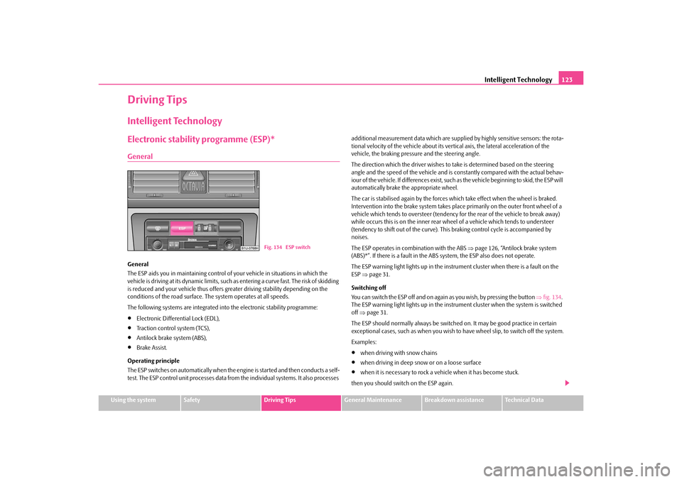
You can switch the ESP off and on agai n as you wish, by pressing the button fig. 134 .
The ESP warning light lights up in the instrument cluster when the system is switched
off page 31.
The ESP should normally always be switched on. It may be good practice in certain
exceptional cases, such as when you wish to have wheel slip, to switch off the system.
Examples:
when driving with snow chains
when driving in deep snow or on a loose surface
when it is necessary to rock a vehicle when it has become stuck.
then you should switch on the ESP again.
Fig. 134 ESP switch
s2rc.book Page 123 Thursday, April 22, 2010 10:58 AM
Page 136 of 207

Towing a trailer135
Using the system
Safety
Driving Tips
General Maintenance
Breakdown assistance
Technical Data
Headlights
Before starting off with a hitched trailer, also check the setting of the headlights. Alter
the setting as necessary with the ai
d of the headlight beam adjuster page 48.
Detachable ball head
The ball rod is detachable on vehicles which feature a factory-fitted towing device. It is
stowed together with separate fitting instructions in the spare wheel well in the
luggage compartment of the vehicle.
Further information on the towing device page 136.
Note
We recommend that you also have your vehicle inspected between service inter-
vals if you tow a trailer frequently.
The handbrake on the towing vehicle must be put on when coupling and decou-
pling the trailer.
Driving Tips
Particular caution is required when towing a trailer.– Do not, as far as possible, drive with your vehicle unladen and the trailer laden.
– Do not make full use of the legal maximum speeds. This applies in particular to downhill sections.
– Apply the brakes in good time.
– Keep a check on the coolant temperature gauge if the outside temperature is high.
Distribution of weight
The distribution of the weight is very poor if your vehicle is unladen and the trailer is
laden. Maintain a particularly low speed if you cannot avoid driving with this combina-
tion.
Driving speed
Do not drive faster than 80 km/hour for safety reasons. This also applies for countries
in which higher speeds are allowed. The fact that the driving stability of the vehicle + trailer combination reduces with
increasing speed means that the legally allowed speed should not be used when there
are unfavourable road, weather or wind cond
itions, particularly near accident black
spots.
You must always reduce your speed immediat ely as soon as you detect even just the
slightest swaying of the trailer. On no account attempt to stop the trailer from
“swaying” by accelerating.
Apply the brakes in good time! If the trailer is fitted with a trailer brake, apply the
brakes gently at first and then brake firmly. This will avoid brake jolts resulting from the
trailer wheels locking. Shift down gears in good time before negotiating a downhill
section to allow the engine to also act as a brake.
Engine overheating
Please keep a check on the coolant temperature gauge if you have to negotiate a
lengthy slope in a low gear at a high engi ne speed when the outside temperature is
very high page 16.
If the needle of the coolant temperature gauge moves into the right-hand area or even
the red area of the scale, reduce your speed immediately. Stop and switch off the
engine if the warning light
in the instrument cluster begins flashing. Wait a few
minutes and check the level of coolant in the coolant expansion bottle page 153,
“Inspecting the coolant level”.
Please refer to the following guidelines page 28, “Coolant temperature/coolant
level ”.
The coolant temperature can be reduced by switching on the heating.
Any increase in the cooling effect of the coolant fan through shifting down a gear and
increasing the engine speed is not possible since the fan speed is independent of the
engine speed. One should also not drop a gear for this reason when towing a trailer as
long as the engine can manage th e slope without any drop in speed.
s2rc.book Page 135 Thursday, April 22, 2010 10:58 AM
Page 152 of 207
Inspecting and replenishing151
Using the system
Safety
Driving Tips
General Maintenance
Breakdown assistance
Technical Data
Oil level within range –You may top up the oil. It is possible that the oil level may then be within range
after doing this.Oil level within range –You must top up the oil page 151. It is sufficient, once this is done, to keep the
oil level within range .
It is normal for the engine to consume oil. The oil consumption may be as much as 0.5
l/1 000 km depending on your style of driving and the conditions under which you
operate your vehicle. The oil consumption may be slightly hi gher than this during the
first 5 000 kilometres.
One should therefore check the oil level at regular intervals, preferably every time after
the fuel tank is filled or after driving for long stretches.
We recommend maintaining the oil level within the range if the engine has been
operating at high loads, for example during a lengthy motorway trip during the
summer months, towing a trailer or negotiating a high mountain pass, but not above
this .
The warning light in the instrument cluster wi ll indicate whether the oil level is too low
page 29. In this case, check the oil level as soon as possible. Top up with an appro-
priate quantity of oil.
Caution
The oil level must on no ac count extend beyond the range . Danger of damaging
the catalytic converter.
Do not continue your journey if for some reason it is not possible under the
conditions prevailing to top up with oil. Switch the engine off and obtain professional
assistance from a specialist garage, otherwise it could lead to severe engine damage.
Replenishing engine oil– Inspecting the engine oil level page 150.
– Unscrew the cap of the engine oil filler opening page 150, fig. 146 .
– Pour in a suitable grade of oil in portions of 0.5 litres page 149. – Inspect the oil level
page 150.
– Carefully screw on the cap of the filler opening and push the dipstick in fully.
WARNING
Avoid dripping oil onto hot parts of the engine when topping up will oil - a
risk of fire!
Read and observe the warning notes page 148, “Working in the engine
compartment” before working in the engine compartment.For the sake of the environment
The oil level must on no account be above the range page 150. Oil will otherwise
be drawn in through the cr ankcase ventilation and may pass through the exhaust
system to atmosphere. The oil may combust in the catalytic converter and damage it.Changing engine oilThe engine oil must be changed at the intervals stated in the Service schedule or
according to the service interval indicator page 18.
WARNING
Only carry out the engine oil change, if you have the required professional
knowledge!
Read and observe the warning notes page 148, “Working in the engine
compartment” before working in the engine compartment.
Let the engine cool down - risk of burning from hot oil.
Wear an eye protection - risk of caustic burns due to oil splashes.
Oil is toxic! Store old oil in a safe place out of the reach of children and unau-
thorized persons until you dispose of it properly.Caution
You must not pour any additives into the engine oil - risk of engine damage! Damage,
which results from such product, are excluded from the warranty.
Ab
Aa
AcAb
AaAa
A2
Aa
s2rc.book Page 151 Thursday, April 22, 2010 10:58 AM
Page 154 of 207

Inspecting and replenishing153
Using the system
Safety
Driving Tips
General Maintenance
Breakdown assistance
Technical Data
Caution
Other coolant additives may cause operational problems which, in partic-
ular, involves significantly reducing the anticorrosion effect.
Any faults or problems resulting from corrosion may cause a loss of coolant
and, as a consequence of this, result in major engine damage.
Inspecting the coolant levelThe coolant expansion bottle is located in the engine compartment on the right.
– Switch the engine off.
– Open the bonnet in “Working in the engine compartment” on page 148.
– Check the level of coolant in the coolant expansion bottle fig. 148 . When the
engine is cold, the coolant level must lie between the and markings. When
the engine is warm, the level may also lie slightly above the hatched part.
If the coolant level in the reservoir is too lo w, this is indicated by the warning light in
the instrument cluster
page 28. We nevertheless recommend inspecting the
coolant level directly at the reservoir from time to time.
Loss of coolant
A loss of coolant is first and foremost an indication of a leak in the system. You should
not merely top up the coolant in the reservoir. It is also important to have the cooling
system inspected without delay by a specialist garage. Losses can only occur through the pressure
relief in the cap of the coolant expansion
bottle which is completely free of leaks if the coolant boils as a result of overheating
and is forced out of the cooling system.
WARNING
Read and observe the warning notes page 148, “Working in the engine
compartment” before working in the engine compartment.
Caution
One should contact a specialist garage as s oon as possible if the source of overheating
itself cannot be determined and removed, since there may be grave damage to the
engine.Replenishing the coolant– Switch the engine off.
– Allow the engine to cool down.
– Place a cloth over the cap of the coolant expansion reservoir fig. 148 and
unscrew the cap carefully by turning it to the left .
–Top up the coolant.
– Screw the cap tight until it is heard to lock.
The coolant which you use for replenishing th e system, must comply with one specific
specification page 152, “Coolant”. Do not use an al ternative additive if the coolant
additive G13 is not available in exceptional cases. Just top up the system with water
and as soon as possible arrange adjustment to correct the mixing ratio of water and
coolant additive again by a specialist garage.
Only use fresh coolant for topping up the system.
Do not top up the fluid above the hatched pa rt! Excess coolant which is heated up is
forced out of the cooling system through th e pressure relief valve in the cap of the
coolant compensation bottle.
Wait until the engine has cooled down for a system which has suffered a major loss of
coolant before pouring in coolant. This is necessary to avoid engine damage.
Fig. 148 Engine compartment:
Coolant expansion bottleAa
Ab
s2rc.book Page 153 Thursday, April 22, 2010 10:58 AM
Page 156 of 207
Inspecting and replenishing155
Using the system
Safety
Driving Tips
General Maintenance
Breakdown assistance
Technical Data
instrument cluster
page 31. In this case stop immediately and do not drive any
further! Obtain professional assistance.
WARNING
Read and observe the warning notes page 148, “Working in the engine
compartment” before working in the engine compartment.
If the fluid level has dropped below the “MIN” marking, do not drive any
further - risk of accident! Obtain professional assistance.
Replacing brake fluidBrake fluid absorbs moisture. This causes the fluid to absorb moisture from the
surrounding air over a period of time. Excessive water in the brake fluid may be the
cause of corrosion in the brake system. The water content also lowers the boiling point
of the brake fluid.
One may only use new genuine brake fluid from Škoda Auto. The brake fluid must
comply with one of the following standards or specifications:
VW 50114
FMVSS 116 DOT4
DIN ISO 4925 CLASS 4
We recommend that you have the brake fluid replaced by an authorised Škoda
Service Partner as part of an Inspection Service.
WARNING
Using old brake fluid can result in severe stress on the brakes because of the
formation of vapour bubbles in the br ake system. This greatly impairs the
braking efficiency and thus also the safety of your vehicle.
Caution
Brake fluid damages the paintwork of the vehicle.
For the sake of the environment
In view of the problems involved with proper disposal of brake fluid, the special tools
and the professional knowledge required, you should have the brake fluid replaced by
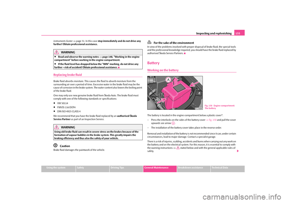
authorised Škoda Service Partners.BatteryWorking on the batteryThe battery is located in the engine compartment below a plastic cover*.
– Press the interlocks on the sides of the battery cover fig. 150 and pull the cover
upwards see arrow .
– The installation of the battery co ver takes place in the reverse order.
Removal and installation of the battery is not recommended since it can, under certain
circumstances, lead to major dama ge. Contact a specialist garage.
There is a risk of injuries, scalding, accidents and burns when carrying out any work on
the battery and on the electrical system. For th is reason, it is essential to comply with
the warning instructions stated below and with the general applicable rules of
safety.
Fig. 150 Engine compartment:
The battery
AA
s2rc.book Page 155 Thursday, April 22, 2010 10:58 AM
Page 180 of 207
Fuses and light bulbs179
Using the system
Safety
Driving Tips
General Maintenance
Breakdown assistance
Technical Data
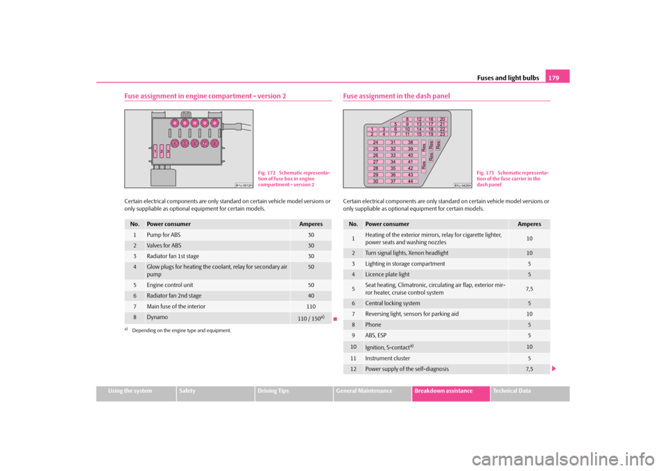
Fuse assignment in engine compartment - version 2Certain electrical components are only standard on certain vehicle model versions or
only suppliable as optional equipment for certain models.
Fuse assignment in the dash panelCertain electrical components are only stan dard on certain vehicle model versions or
only suppliable as optional equipment for certain models.
No.
Power consumer
Amperes
1
Pump for ABS
30
2
Va lve s for AB S
30
3
Radiator fan 1st stage
30
4
Glow plugs for heating the coolant, relay for secondary air
pump
50
5
Engine control unit
50
6
Radiator fan 2nd stage
40
7
Main fuse of the interior
110
8
Dynamo
110 / 150
a)
a)Depending on the engine type and equipment.
Fig. 172 Schematic representa-
tion of fuse box in engine
compartment - version 2
No.
Power consumer
Amperes
1
Heating of the exterior mirrors, relay for cigarette lighter,
power seats and washing nozzles
10
2
Turn signal lights, Xenon headlight
10
3
Lighting in storage compartment
5
4
Licence plate light
5
5
Seat heating, Climatronic, circulating air flap, exterior mir-
ror heater, cruise control system
7,5
6
Central locking system
5
7
Reversing light, sensors for parking aid
10
8
Phone
5
9
ABS, ESP
5
10
Ignition, S-contact
a)
10
11
Instrument cluster
5
12
Power supply of the self-diagnosis
7,5
Fig. 173 Schematic representa-
tion of the fuse carrier in the
dash panel
s2rc.book Page 179 Thursday, April 22, 2010 10:58 AM