reset SKODA OCTAVIA TOUR 2011 2.G / (1Z) Owner's Manual
[x] Cancel search | Manufacturer: SKODA, Model Year: 2011, Model line: OCTAVIA TOUR, Model: SKODA OCTAVIA TOUR 2011 2.G / (1Z)Pages: 183, PDF Size: 11.13 MB
Page 16 of 183

Instruments and Indicator/Warning Lights15
Using the system
Safety
Driving Tips
General Maintenance
Breakdown assistance
Technical Data
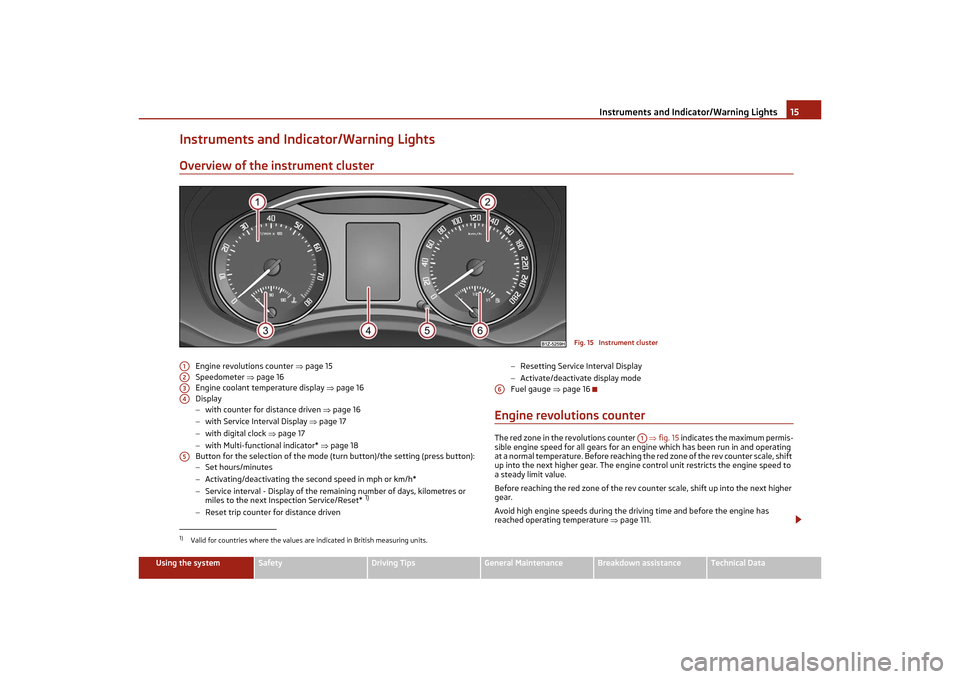
Instruments and Indicator/Warning LightsOverview of the instrument cluster
Engine revolutions counter page 15
Speedometer page 16
Engine coolant temperature display page 16
Display
− with counter for distance driven page 16
− with Service Interval Display page 17
− with digital clock page 17
− with Multi-functional indicator* page 18
Button for the selection of the mode (t urn button)/the setting (press button):
− Set hours/minutes
− Activating/deactivating the second speed in mph or km/h*
− Service interval - Display of the remaining number of days, kilometres or
miles to the next Inspection Service/Reset*
1)
−Reset trip counter for distance driven −
Resetting Service Interval Display
− Activate/deactivate display mode
Fuel gauge page 16
Engine revolutions counterThe red zone in the revolutions counter fig. 15 indicates the maximum permis-
sible engine speed for all gears for an engine which has been run in and operating
at a normal temperature. Before reaching th e red zone of the rev counter scale, shift
up into the next higher gear. The engine control unit restricts the engine speed to
a steady limit value.
Before reaching the red zone of the rev coun ter scale, shift up into the next higher
gear.
Avoid high engine speeds during the driving time and before the engine has
reached operating temperature page 111.
Fig. 15 Instrument cluster
1)Valid for countries where the values are indicated in British measuring units.A1A2A3A4A5
A6
A1
s2lk.2.book Page 15 Monday, April 18, 2011 7:41 AM
Page 17 of 183

Instruments and Indicator/Warning Lights
16For the sake of the environment
Shifting up early helps you save fuel and reduce the operating noise of your
vehicle.SpeedometerThe speedometer shows the current speed of the car.Engine coolant temperature DisplayThe coolant temperature gauge page 15, fig. 15 operates only when the igni-
tion is switched on.
In order to avoid any damage to the engine, please pay attention to the following
notes regarding the temperature ranges:
Cold range
If the pointer is in the left-hand area of the scale it means that the engine has not
yet reached its operating temperature. Avoid running at high engine speeds, at full
throttle and at severe engine loads.
The operating range
The engine has reached its operating temp erature as soon as the pointer moves
into the mid-range of the scale. The pointer may also move further to the right at
high engine loads and high outside temperat ures. This is not critical provided the
warning symbol
in the instrument cluster does not flash.
If the symbol
in the instrument cluster flashes it means that either the coolant
temperature is too high or the coolant level is too low. Observe the guidelines
page 25, “Coolant temperature/coolant level ”.
WARNING
Pay attention to the warning notes page 131, “Working in the engine compart-
ment” before opening the bonnet and inspecting the coolant level.
Caution
Additional headlights and other attached components in front of the fresh air inlet
impair the cooling efficiency of the coolant. There is then a risk of the engine over-
heating at high outside temperatures and high engine loads!
Fuel gaugeThe fuel gauge page 15, fig. 15 only works when the ig nition is switched on.
The fuel tank has a capacity of ab out 55 litres. The warning symbol
in the instru-
ment cluster lights up when the pointer reaches the reserve marking. There are
now about 9 litres of fuel remaining in the tank. This symbol is a reminder for you,
that you must refuel .
An acoustic signal sounds as an additional reminder.
Caution
Never run the fuel tank completely empty! The irregular supply of the fuel system
can lead to irregular running of the engine. Unburnt fuel may get into the exhaust
system and damage the catalytic converter.Counter for distance drivenThe distance which you have driven with yo ur vehicle is shown in kilometres (km).
In some countries the measuring unit “mile” is used.
Reset button
Hold the reset button page 15, fig. 15 pressed for approx. 1 second. The trip
counter is reset to zero.
Trip counter for distance driven
The trip counter shows the distance driven since the time the trip counter was last
erased. The trip is shown in steps of 100 metres or 1/10 of a mile.
Odometer
The odometer indicates the total distance in kilometres or miles which the vehicle
has been driven.
Fault display
If there is a fault in the instrument cluster Error will appear in the display. Contact a
specialist garage.
WARNING
Never seek to adjust the trip counter fo r distance driven while driving for safety
reasons!
A3
A6
A5
s2lk.2.book Page 16 Monday, April 18, 2011 7:41 AM
Page 18 of 183

Instruments and Indicator/Warning Lights17
Using the system
Safety
Driving Tips
General Maintenance
Breakdown assistance
Technical Data
Note
If the display of the second speed is activated in mph or km/h, this speed is shown
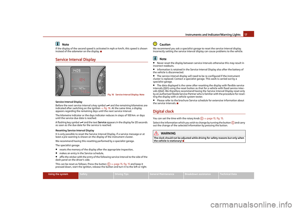
instead of the odometer on the display.Service Interval DisplayService Interval Display
Before the next service interval a key symbol
and the remaining kilometres are
indicated after switching on the ignition fig. 16 . At the same time, a display
appears regarding the remaining days until the next service interval.
The kilometre indicator or the days indicator reduces in steps of 100 km. or days
until the service due date is reached.
A flashing key symbol
and the text Service appears in the display for 20 seconds
as soon as the due date for the service is reached.
Resetting Service Interval Display
It is only possible to reset the Service In terval Display, if a service message or at
least a pre-warning is shown on the display of the instrument cluster.
We recommend having this resetting performed by a specialist garage.
The specialist garage:
•
resets the memory of the display after the appropriate inspection,
•
makes an entry in the Service schedule,
•
affix the sticker with the entry of the follo wing service interval to the side of the
dash panel on the driver's side.
This can be reset as follows: Press the button page 15, fig. 15 and keep it
pressed down, start the ignition, release the button and turn it to the left or right.
Caution
We recommend you ask a specialist garage to reset the service interval display.
Incorrectly setting the service interval display can cause problems to the vehicle.
Note
•
Never reset the display between service intervals otherwise this may result in
incorrect readouts.
•
information is retained in the Service Interval Display also after the battery of
the vehicle is disconnected.
•
The service interval display will need to be re-configured if the instrument
cluster is replaced. Contact a specialist garage. This work is carried out by a
specialist garage.
•
The data displayed is the same after rese tting the display with flexible service
intervals (QG1) using the reset button as th at for a vehicle with fixed service inter-
vals (QG2). We therefore recommend having the Service Interval Display reset only
by an authorised Škoda Service Partner who is familiar with the procedure for reset-
ting the display with a vehicle system tester.
•
Please refer to the brochure Service schedule for extensive information about
the service intervals.
Digital clockYou can set the time with the rotary knob page 15, fig. 15 .
Select the information which you wish to change by turning the button and carry
out the change of the selected information by pressing the button.
WARNING
The clock should not be adjusted while dr iving for safety reasons but only when
the vehicle is stationary!
Fig. 16 Service Interval Display: NoteA5
A5
A5
s2lk.2.book Page 17 Monday, April 18, 2011 7:41 AM