brake sensor SKODA RAPID 2012 1.G Owner's Manual
[x] Cancel search | Manufacturer: SKODA, Model Year: 2012, Model line: RAPID, Model: SKODA RAPID 2012 1.GPages: 180, PDF Size: 4.36 MB
Page 18 of 180

Auto Check Control
First read and observe the introductory information and safety warn-
ings on page 14.
Vehicle condition
Certain functions and conditions of individual vehicle systems are checked contin-
uously when the ignition is switched on and also while driving.
Some error messages and other information are displayed in the information dis-
play. The messages are displayed at the same time as the symbols in the informa-
tion display or the warning lights in the instrument cluster
» page 16.
If there is at least one error message, the menu item Vehicle status is displayed
in the menu. After selecting this menu, the first of the error messages is dis-
played. Several error messages are shown on the display under the message e.g.
1/3. This indicates that the first of a total of three error messages is being dis-
played.
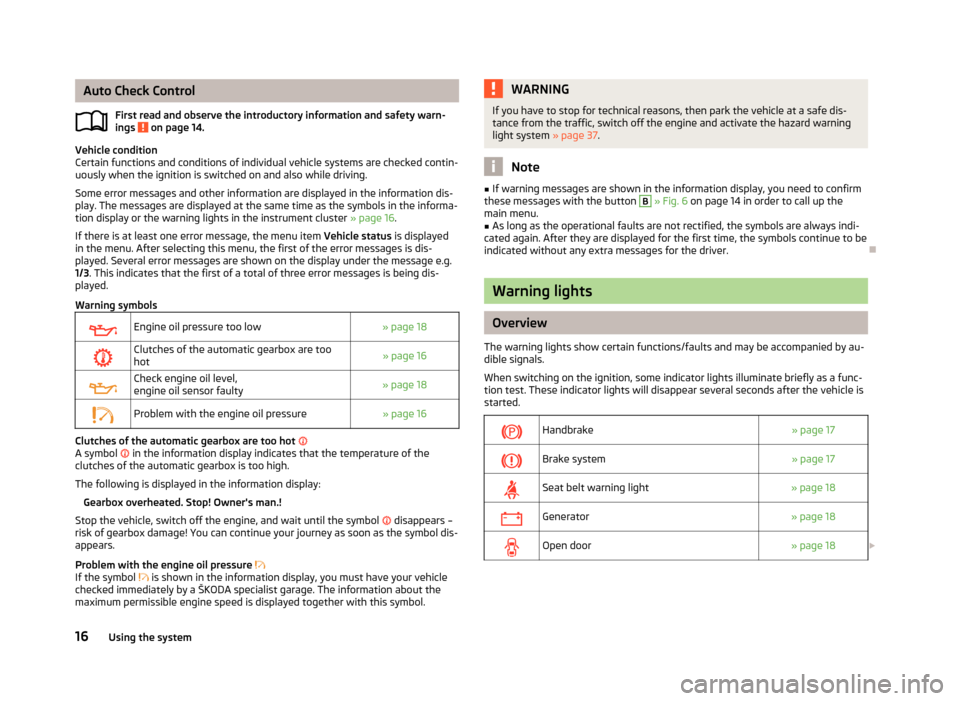
Warning symbols
Engine oil pressure too low
» page 18
Clutches of the automatic gearbox are too
hot » page 16
Check engine oil level,
engine oil sensor faulty
» page 18
Problem with the engine oil pressure
» page 16Clutches of the automatic gearbox are too hot
A symbol in the information display indicates that the temperature of the
clutches of the automatic gearbox is too high.
The following is displayed in the information display: Gearbox overheated. Stop! Owner's man.!
Stop the vehicle, switch off the engine, and wait until the symbol disappears –
risk of gearbox damage! You can continue your journey as soon as the symbol dis-
appears.
Problem with the engine oil pressure
If the symbol is shown in the information display, you must have your vehicle
checked immediately by a
ŠKODA specialist garage. The information about the
maximum permissible engine speed is displayed together with this symbol.
ä WARNING
If you have to stop for technical reasons, then park the vehicle at a safe dis-
tance from the traffic, switch off the engine and activate the hazard warning
light system » page 37. Note
■ If warning messages are shown in the information display, you need to confirm
these messages with the button B
» Fig. 6 on page 14 in order to call up the
main menu. ■ As long as the operational faults are not rectified, the symbols are always indi-
cated again. After they are displayed for the first time, the symbols continue to be
indicated without any extra messages for the driver. Ð Warning lights
Overview
The warning lights show certain functions/faults and may be accompanied by au-
dible signals.
When switching on the ignition, some indicator lights illuminate briefly as a func-
tion test. These indicator lights will disappear several seconds after the vehicle is
started.
Handbrake
» page 17
Brake system
» page 17
Seat belt warning light
» page 18
Generator
» page 18
Open door
» page 18£16
Using the system
Page 77 of 180

Activating/deactivating the parking aid
The parking aid is activated automatically when
reverse gear is engaged and the
ignition is turned on. This is confirmed by a brief audible signal.
The parking aid is deactivated by removing the reverse gear. WARNING
■ The parking aid is not a substitute for the driver paying proper attention and
it is always the driver's responsibility to take care when reversing the vehicle
or carrying out similar manoeuvres. Pay particular attention to small children
and animals as they are not recognised by the parking aid sensors.
■ Before reversing or parking, check that there is no small obstacle, such as a
rock, thin post, trailer drawbar etc., in front of or behind the vehicle. Such ob-
stacles may not be recognised by the parking aid sensors.
■ Under certain circumstances, surfaces of certain objects and types of cloth-
ing cannot reflect the signals from the parking aid. Thus, these objects or peo-
ple who wear such clothing are not recognised by the parking aid sensors.
■ External sound sources can have a detrimental effect on the parking aid.
Under unfavourable conditions, objects or people may not be recognised. Note
■ If a warning signal sounds for 3 seconds every time you activate the system,
this indicates a system fault. Have the fault rectified by a ŠKODA specialist ga-
rage. ■ The sensors must be kept clean (free of ice, etc.) to enable the parking aid to
operate properly.
■ If the parking aid is activated and the selector lever of the automatic gearbox is
in the position P , the warning signal is interrupted (the vehicle cannot move). ÐCruise control system (CCS)
ä
Introduction
This chapter contains information on the following subjects:
Storing a speed 76
Changing a stored speed 76
Switching off the cruise control system temporarily 76
Switching off the cruise control system completely 76The cruise control system (CCS) maintains a constant speed, more than 30
km/h,
once it has been set, without you having to depress the accelerator pedal. This is
only possible within the range which is permitted by the power output and brak-
ing power of the engine.
The warning light illuminates in the instrument cluster when the cruise control
system is activated. WARNING
■ For safety reasons, the cruise control system must not be used in dense
traffic or on unfavourable road surfaces (such as icy roads, slippery roads,
loose gravel) – risk of accident! ■ The saved speed may only be resumed if it is not too high for the current
traffic conditions. ■ Always switch off the cruise control system after use to prevent uninten-
tional use of the system. CAUTION
■ The cruise control system is not able to maintain a constant speed when driving
in areas with steeper gradients. The weight of the vehicle increases the speed at
which it travels. Therefore, shift to a lower gear in good time or slow the vehicle
down by applying the foot brake. Note
■ It is not possible on vehicles fitted with an automatic gearbox to switch on the
cruise control system if the selector lever is in the position P, N or R.
■ It is not possible to switch on the cruise control system on vehicles fitted with a
manual gearbox if the first gear or reverse gear is engaged. Ð
75
Starting-off and Driving
Page 119 of 180

General Maintenance
Taking care of and cleaning the vehicle
Taking care of your vehicle
ä
Introduction
This chapter contains information on the following subjects:
Washing the vehicle 118
Automatic car wash systems 118
Washing by hand 118
Washing with a high-pressure cleaner 118
Preserving and polishing the vehicle paintwork 119
Chrome parts 119
Paint damage 119
Plastic parts 119
De-icing windows and exterior mirrors 120
Radio reception and aerial 120
Headlight lenses 120
Rubber seals 120
Door lock cylinders 120
Wheels 121
Underbody protection 121
Protection of hollow spaces 121
Artificial leather and materials 122
Fabric covers on electrically heated seats 122
Natural leather 122
Seat belts 123
Regular and proper care help to retain the efficiency and value of your vehicle. It
may also be one of the requirements for the acceptance of warranty claims relat-
ing to corrosion damage and paint defects on the bodywork.
We recommend using care products from
ŠKODA Original Accessories that are
available from ŠKODA Service Partners. The instructions for use on the package
must be observed. WARNING
■ Care products may be harmful to your health if not used according to the in-
structions.
■ Always store care products in a safe place, out of the reach of children – risk
of poisoning! ■ When washing your vehicle in the winter: Water and ice in the brake system
can affect the braking efficiency – risk of accident! ■ Only wash the vehicle when the ignition is switched off – risk of accident!
■ Protect your hands and arms from sharp-edged metal parts when cleaning
the underfloor, the inside of the wheel housings or the wheel trims – risk of
cuts!
■ Air fresheners and scents can be hazardous to heath when the temperature
inside the vehicle is high. CAUTION
■ Be sure to check clothing for colourfastness to avoid any damage or visible
stains on the material (leather), panels and textiles.
■ Cleaners containing solvents can damage the material being cleaned.
■ Do not wash your vehicle in bright sunlight – risk of paint damage.
■ If washing the vehicle in the winter using a hose or high-pressure cleaner, en-
sure that the jet of water is not aimed directly at the locking cylinders or the
door/panel joints – risk of freezing!
■ Do not use any insect sponges, rough kitchen sponges or similar cleaning prod-
ucts – risk of damaging the surface of paintwork. ■ Do not stick any stickers on the inside of the rear windows, in the vicinity of the
heating elements or near the window aerial. These may get damaged. With re-
gard to the antenna, they may interfere with the radio or navigation system.
■ Do not clean the inside of the windows with sharp-edged objects or corrosive
and acidic cleaning agents – risk of damaging the heating elements or window
aerial.
■ Do not attach scents and air fresheners to the dashboard – risk of damage to
the dashboard.
■ To avoid damaging the parking aid sensors while cleaning with high-pressure
cleaners or steam jets, the sensors must only be directly sprayed for short periods
while a minimum distance of 10 cm must be observed.
■ Do not clean the roof trim with a brush – risk of damage to the trim surface. £
117
Taking care of and cleaning the vehicle
Page 143 of 180

Full wheel trim
First read and observe the introductory information and safety warn-
ings on page 137.
Pulling off
›
Hook the clamp found in the vehicle tool kit into the reinforced edge of the
wheel trim.
› Push the wheel wrench through the clamp, support on the tyre and pull off the
wheel trim.
Install
› First press the full wheel trim onto the wheel rim at the valve opening provided.
Then press the full wheel trim into the wheel rim until its entire circumference
locks correctly in place. CAUTION
■ Use the pressure of your hand, do not knock the full wheel trim! Heavy knocks
mainly on the points where the full wheel trim has not been inserted into the
wheel, can result in damage to the guide and centring elements of the full wheel
trim.
■ First of all check that the theft-deterrent wheel bolt is located in the hole near
the valve before fitting the full wheel trim onto a steel wheel which is attached
with a theft-deterrent wheel bolt » page 149, Securing wheels against theft .
■ If wheel trims are retrofitted it must be ensured that an adequate flow of air is
assured to cool the brake system. ÐWheel bolts
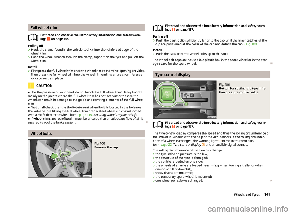
Fig. 108
Remove the cap
ä
First read and observe the introductory information and safety warn-
ings on page 137.
Pulling off
›
Push the plastic clip sufficiently far onto the cap until the inner catches of the
clip are positioned at the collar of the cap and detach the cap » Fig. 108.
Install
› Push the caps onto the wheel bolts up to the stop.
The wheel bolt caps are housed in a plastic box in the spare wheel or in the stor-
age space for the spare wheel. Ð Tyre control display
Fig. 109
Button for setting the tyre infla-
tion pressure control value
First read and observe the introductory information and safety warn-
ings on page 137.
The tyre control display compares the speed and thus the rolling circumference of
the individual wheels with the help of the ABS sensors. If the rolling circumfer-
ence of a wheel is changed, the warning light
in the instrument clus-
ter » page 22, Tyre control display and an audible signal sounds.
The rolling circumference of the tyre can change if: › the tyre inflation pressure is too low;
› the structure of the tyre is damaged;
› the vehicle is loaded on one side;
› the wheels of an axle are loaded heavily (e.g. when towing a trailer or when
driving uphill or downhill);
› snow chains are mounted;
› the temporary spare wheel is mounted;
› one wheel per axle was changed.
£
ä
ä 141
Wheels and Tyres
Page 159 of 180

Fuses in the dash panel
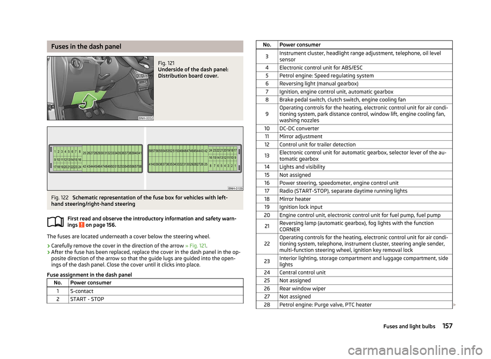
Fig. 121
Underside of the dash panel:
Distribution board cover. Fig. 122
Schematic representation of the fuse box for vehicles with left-
hand steering/right-hand steering
First read and observe the introductory information and safety warn-
ings on page 156.
The fuses are located underneath a cover below the steering wheel.
› Carefully remove the cover in the direction of the arrow
» Fig. 121.
› After the fuse has been replaced, replace the cover in the dash panel in the op-
posite direction of the arrow so that the guide lugs are guided into the open-
ings of the dash panel. Close the cover until it clicks into place.
Fuse assignment in the dash panel No. Power consumer
1 S-contact
2 START - STOP ä No. Power consumer
3 Instrument cluster, headlight range adjustment, telephone, oil level
sensor
4 Electronic control unit for ABS/ESC 5 Petrol engine: Speed regulating system
6 Reversing light (manual gearbox) 7 Ignition, engine control unit, automatic gearbox
8 Brake pedal switch, clutch switch, engine cooling fan
9 Operating controls for the heating, electronic control unit for air condi-
tioning system, park distance control, window lift, engine cooling fan,
washing nozzles
10 DC-DC converter 11 Mirror adjustment
12 Control unit for trailer detection
13 Electronic control unit for automatic gearbox, selector lever of the au-
tomatic gearbox
14 Lights and visibility 15 Not assigned
16 Power steering, speedometer, engine control unit 17 Radio (START-STOP), separate daytime running lights
18 Mirror heater 19 Ignition lock input
20 Engine control unit, electronic control unit for fuel pump, fuel pump
21 Reversing lamp (automatic gearbox), fog lights with the function
CORNER
22 Operating controls for the heating, electronic control unit for air condi-
tioning system, telephone, instrument cluster, steering angle sender,
multi-function steering wheel, ignition key removal lock
23 Interior lighting, storage compartment and luggage compartment, side
lights
24 Central control unit 25 Not assigned
26 Rear window wiper 27 Not assigned
28 Petrol engine: Purge valve, PTC heater £ 157
Fuses and light bulbs