fuse box SKODA RAPID 2012 1.G Owner's Manual
[x] Cancel search | Manufacturer: SKODA, Model Year: 2012, Model line: RAPID, Model: SKODA RAPID 2012 1.GPages: 180, PDF Size: 4.36 MB
Page 9 of 180
Using the system
Cockpit
Overview
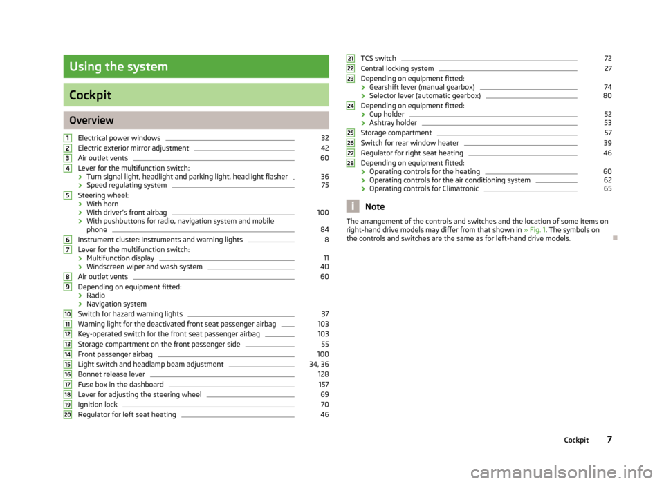
Electrical power windows 32
Electric exterior mirror adjustment 42
Air outlet vents 60
Lever for the multifunction switch:
› Turn signal light, headlight and parking light, headlight flasher 36
› Speed regulating system 75
Steering wheel:
› With horn
› With driver’s front airbag 100
› With pushbuttons for radio, navigation system and mobile
phone 84
Instrument cluster: Instruments and warning lights 8
Lever for the multifunction switch:
› Multifunction display 11
› Windscreen wiper and wash system 40
Air outlet vents 60
Depending on equipment fitted:
› Radio
› Navigation system
Switch for hazard warning lights 37
Warning light for the deactivated front seat passenger airbag 103
Key-operated switch for the front seat passenger airbag 103
Storage compartment on the front passenger side 55
Front passenger airbag 100
Light switch and headlamp beam adjustment 34, 36
Bonnet release lever 128
Fuse box in the dashboard 157
Lever for adjusting the steering wheel 69
Ignition lock 70
Regulator for left seat heating 461
2
3
4
5
6
7
8
9
10
11
12
13
14
15
16
17
18
19
20 TCS switch 72
Central locking system 27
Depending on equipment fitted:
› Gearshift lever (manual gearbox) 74
› Selector lever (automatic gearbox) 80
Depending on equipment fitted:
› Cup holder 52
› Ashtray holder 53
Storage compartment 57
Switch for rear window heater 39
Regulator for right seat heating 46
Depending on equipment fitted:
› Operating controls for the heating 60
› Operating controls for the air conditioning system 62
› Operating controls for Climatronic 65
Note
The arrangement of the controls and switches and the location of some items on
right-hand drive models may differ from that shown in »
Fig. 1. The symbols on
the controls and switches are the same as for left-hand drive models. Ð 21
22
23
24
25
26
27
28
7
Cockpit
Page 36 of 180
Lights and visibility
Lights
ä
Introduction
This chapter contains information on the following subjects:
Switching lights on and off 34
Function DAY LIGHT (daytime running lights) 35
Fog lights 35
Rear fog light 35
Headlamp range adjustment 36
Turn signal and main beam lever 36
Parking light 37
Fog lights with the function CORNER 37
Switches for the hazard warning light system 37
On models fitted with right-hand steering the position of certain switches differs
from that shown in » Fig. 18 on page 34. The symbols which mark the switch po-
sitions are identical, however. WARNING
Never drive with only the side lights on! The side lights are not bright enough
to light up the road sufficiently in front of you or to be seen by other oncom-
ing traffic. Therefore always switch on the low beam when it is dark or if visi-
bility is poor. CAUTION
■ The activation of the lights should only be undertaken in accordance with na-
tional legal requirements.
■ The driver is always responsible for the correct settings and use of the lights. Note
■ If the light switch is in the position , the ignition key is removed and the driv-
er's door is open, an audible warning signal will sound. The audible warning signal
is switched off by means of the door contact when the driver's door is closed (ig-
nition off), however, the side lights remain on to illuminate the parked vehicle if
necessary. ■ In the event of cool or humid weather conditions, the headlights can be misted
up from inside. The temperature difference between interior and external area of
the headlight lenses is decisive. When the driving lights are switched on, the light
outlet surfaces are free from mist after a short period, although the headlight
lenses may still be misted up in the peripheral areas. It also concerns reverse light
and turn signal lights. This mist has no influence on the life of the lighting system. Ð Switching lights on and off
Fig. 18
Dash panel: Light switch/fuse box: Switch for daytime running lights
First read and observe the introductory information and safety warn-
ings on page 34.
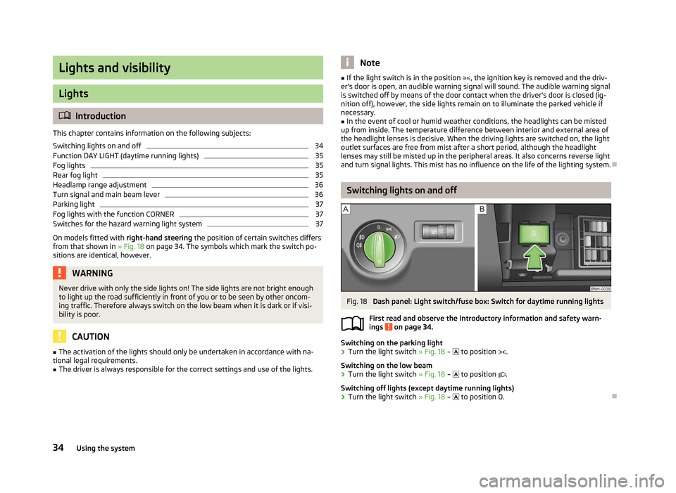
Switching on the parking light
›
Turn the light switch
» Fig. 18 – to position .
Switching on the low beam
› Turn the light switch
» Fig. 18 – to position .
Switching off lights (except daytime running lights)
› Turn the light switch
» Fig. 18 – to position 0.Ð
ä
34 Using the system
Page 37 of 180
Function DAY LIGHT (daytime running lights)
First read and observe the introductory information and safety warn-
ings on page 34.
Switching on daytime running lights
Turn the light switch
» Fig. 18 on page 34 – to position 0.
Deactivating daytime running lights
› Remove the cover of the fuse box
» page 157, Fuses in the dash panel.
› Press the button
» Fig. 18 on page 34 – on the right.
Activating daytime running lights
› Remove the cover of the fuse box
» page 157, Fuses in the dash panel.
› Press the button
» Fig. 18 on page 34 – on the left .
Deactivating daytime running lights on vehicles with the START-STOP system
› Switch off the ignition.
› At the same time, pull the turn signal light lever
» Fig. 21 on page 36 towards
the steering wheel, push it downwards, and hold it in this position.
› Switch on the ignition – wait until the left-turn signal light flashes 4x.
› Switch off the ignition – an audible signal sounds which confirms the deactiva-
tion of the daytime running lights.
› Release the turn signal lever.
Activating daytime running lights on vehicles with the
START-STOP system
› Switch off the ignition.
› At the same time, pull the turn signal light lever
» Fig. 21 on page 36 towards
the steering wheel, push it upwards, and hold it in this position.
› Switch on the ignition – wait until the right-turn signal light flashes 4x.
› Switch off the ignition – an audible signal sounds which confirms the activation
of the daytime running lights.
› Release the turn signal lever. Note
The daytime running lights will come on when the ignition is switched on. Ð
ä Fog lights
Fig. 19
Dash panel: Light switch
First read and observe the introductory information and safety warn-
ings on page 34.
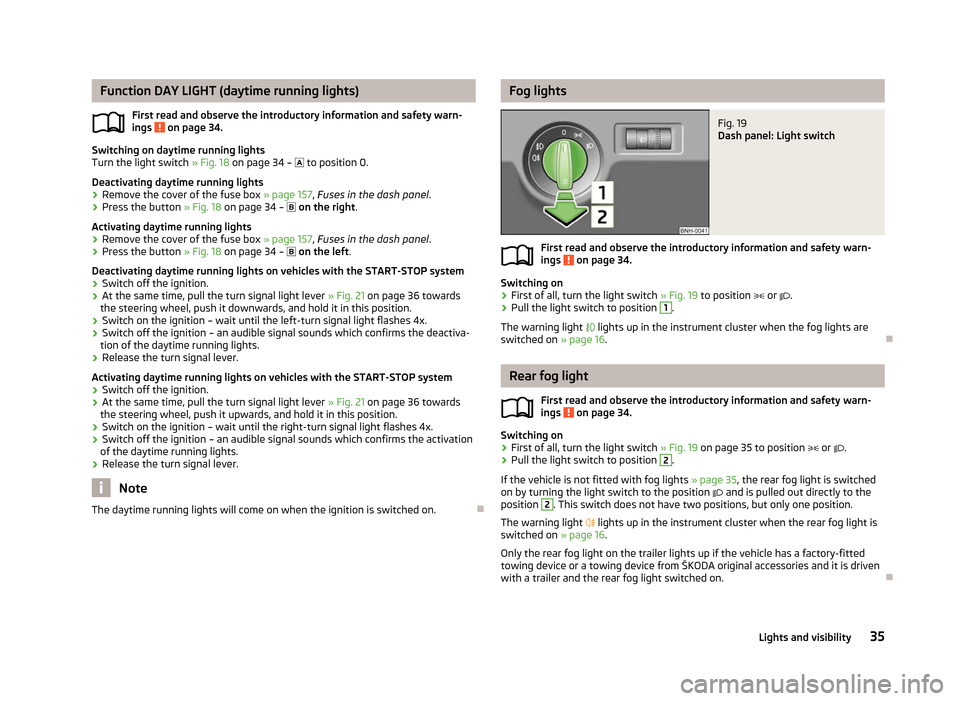
Switching on
›
First of all, turn the light switch
» Fig. 19 to position or .
› Pull the light switch to position 1
.
The warning light lights up in the instrument cluster when the fog lights are
switched on » page 16. Ð Rear fog light
First read and observe the introductory information and safety warn-
ings on page 34.
Switching on
›
First of all, turn the light switch
» Fig. 19 on page 35 to position or .
› Pull the light switch to position 2
.
If the vehicle is not fitted with fog lights » page 35, the rear fog light is switched
on by turning the light switch to the position and is pulled out directly to the
position 2
. This switch does not have two positions, but only one position.
The warning light
lights up in the instrument cluster when the rear fog light is
switched on » page 16.
Only the rear fog light on the trailer lights up if the vehicle has a factory-fitted
towing device or a towing device from ŠKODA original accessories and it is driven
with a trailer and the rear fog light switched on. Ð
ä
ä
35
Lights and visibility
Page 85 of 180
Selector lever-emergency unlocking
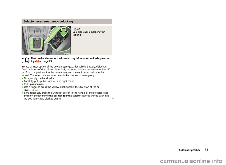
Fig. 72
Selector lever-emergency un-
locking
First read and observe the introductory information and safety warn-
ings on page 79.
In case of interruption of the power supply (e.g. flat vehicle battery, defective
fuse) or defect of the selector lever lock, the selector lever can no longer be shif-
ted from the position
P in the normal way and the vehicle can no longer be
moved. The selector lever must be unlocked in case of emergency.
› Firmly apply the handbrake.
› Carefully pull up the front left and right cover.
› Pull up rear cover.
› Use a finger to press the yellow plastic part in the direction of the ar-
row » Fig. 72.
› Simultaneously press the Shiftlock button in the handle of the selector lever
and shift the lever into the position N (if the selector lever is shifted back into
the position P , it is blocked again). Ðä
83
Automatic gearbox
Page 158 of 180
Fuses and light bulbs
Fuses
ä
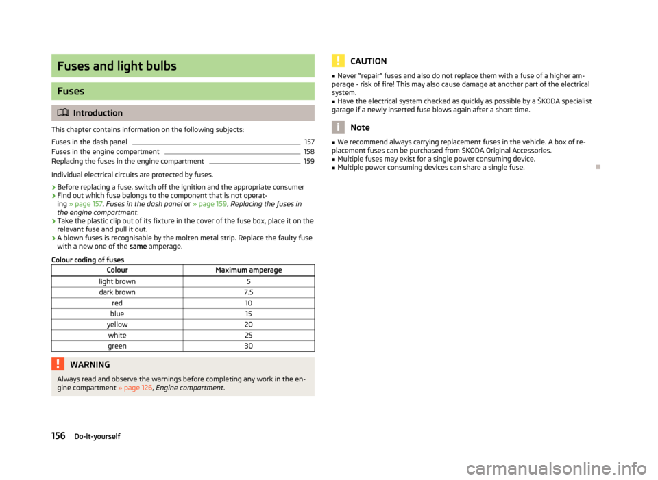
Introduction
This chapter contains information on the following subjects:
Fuses in the dash panel 157
Fuses in the engine compartment 158
Replacing the fuses in the engine compartment 159
Individual electrical circuits are protected by fuses.
› Before replacing a fuse, switch off the ignition and the appropriate consumer
› Find out which fuse belongs to the component that is not operat-
ing » page 157 , Fuses in the dash panel or » page 159 , Replacing the fuses in
the engine compartment .
› Take the plastic clip out of its fixture in the cover of the fuse box, place it on the
relevant fuse and pull it out.
› A blown fuses is recognisable by the molten metal strip. Replace the faulty fuse
with a new one of the
same amperage.
Colour coding of fuses Colour Maximum amperage
light brown 5
dark brown 7.5
red 10
blue 15
yellow 20
white 25
green 30WARNING
Always read and observe the warnings before completing any work in the en-
gine compartment » page 126, Engine compartment . CAUTION
■ Never “repair” fuses and also do not replace them with a fuse of a higher am-
perage - risk of fire! This may also cause damage at another part of the electrical
system.
■ Have the electrical system checked as quickly as possible by a ŠKODA specialist
garage if a newly inserted fuse blows again after a short time. Note
■ We recommend always carrying replacement fuses in the vehicle. A box of re-
placement fuses can be purchased from
ŠKODA Original Accessories.
■ Multiple fuses may exist for a single power consuming device.
■ Multiple power consuming devices can share a single fuse. Ð
156 Do-it-yourself
Page 159 of 180
Fuses in the dash panel
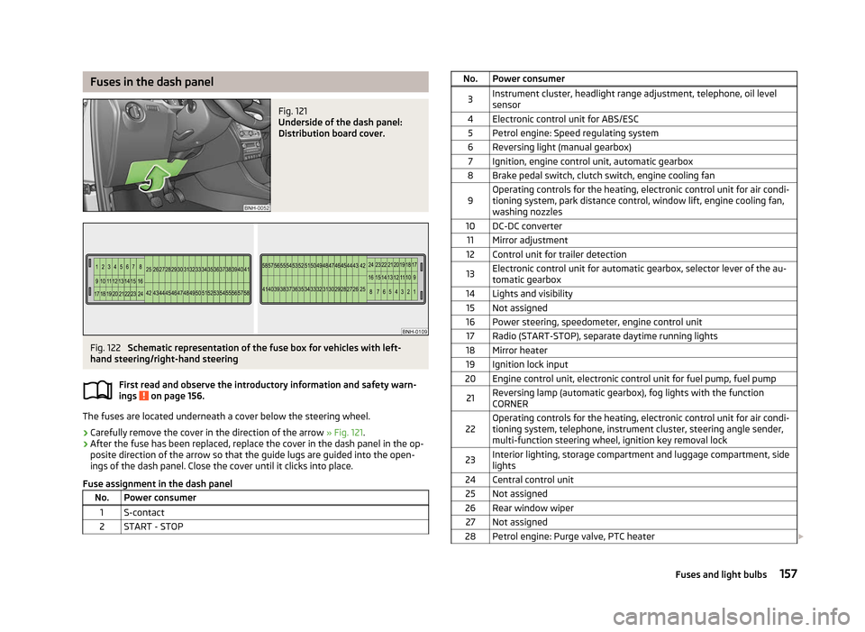
Fig. 121
Underside of the dash panel:
Distribution board cover. Fig. 122
Schematic representation of the fuse box for vehicles with left-
hand steering/right-hand steering
First read and observe the introductory information and safety warn-
ings on page 156.
The fuses are located underneath a cover below the steering wheel.
› Carefully remove the cover in the direction of the arrow
» Fig. 121.
› After the fuse has been replaced, replace the cover in the dash panel in the op-
posite direction of the arrow so that the guide lugs are guided into the open-
ings of the dash panel. Close the cover until it clicks into place.
Fuse assignment in the dash panel No. Power consumer
1 S-contact
2 START - STOP ä No. Power consumer
3 Instrument cluster, headlight range adjustment, telephone, oil level
sensor
4 Electronic control unit for ABS/ESC 5 Petrol engine: Speed regulating system
6 Reversing light (manual gearbox) 7 Ignition, engine control unit, automatic gearbox
8 Brake pedal switch, clutch switch, engine cooling fan
9 Operating controls for the heating, electronic control unit for air condi-
tioning system, park distance control, window lift, engine cooling fan,
washing nozzles
10 DC-DC converter 11 Mirror adjustment
12 Control unit for trailer detection
13 Electronic control unit for automatic gearbox, selector lever of the au-
tomatic gearbox
14 Lights and visibility 15 Not assigned
16 Power steering, speedometer, engine control unit 17 Radio (START-STOP), separate daytime running lights
18 Mirror heater 19 Ignition lock input
20 Engine control unit, electronic control unit for fuel pump, fuel pump
21 Reversing lamp (automatic gearbox), fog lights with the function
CORNER
22 Operating controls for the heating, electronic control unit for air condi-
tioning system, telephone, instrument cluster, steering angle sender,
multi-function steering wheel, ignition key removal lock
23 Interior lighting, storage compartment and luggage compartment, side
lights
24 Central control unit 25 Not assigned
26 Rear window wiper 27 Not assigned
28 Petrol engine: Purge valve, PTC heater £ 157
Fuses and light bulbs
Page 160 of 180
No. Power consumer
29 Injection, coolant pump
30 Fuel pump, ignition system, cruise control 31 Lambda probe
32 High pressure fuel pump, pressure valve
33 Engine control unit
34 Engine control unit, vacuum pump
35 Switch illumination, number plate light, parking light, headlamp washer
system
36 Main beam 37 Rear fog light, DC-DC converter
38 Fog lights 39 Air blower for heating
40 Not assigned 41 Heated front seats
42 Rear window heater
43 Horn
44 Windscreen wipers 45 Boot lid lock, central locking system
46 Alarm 47 Cigarette lighter, power socket in the luggage compartment
48 ABS 49 Turn signal lights, brake lights50 DC-DC converter, radio 51 Electric windows (driver's window and rear left window)
52 Electric windows (front passenger's window and rear right)
53 Windscreen washer
54 START-STOP instrument cluster, steering wheel module, multi-function
steering wheel
55 Control unit for automatic gearbox
56 Headlight cleaning system 57 Low beam on the left
58 Low beam on the right Ð Fuses in the engine compartment
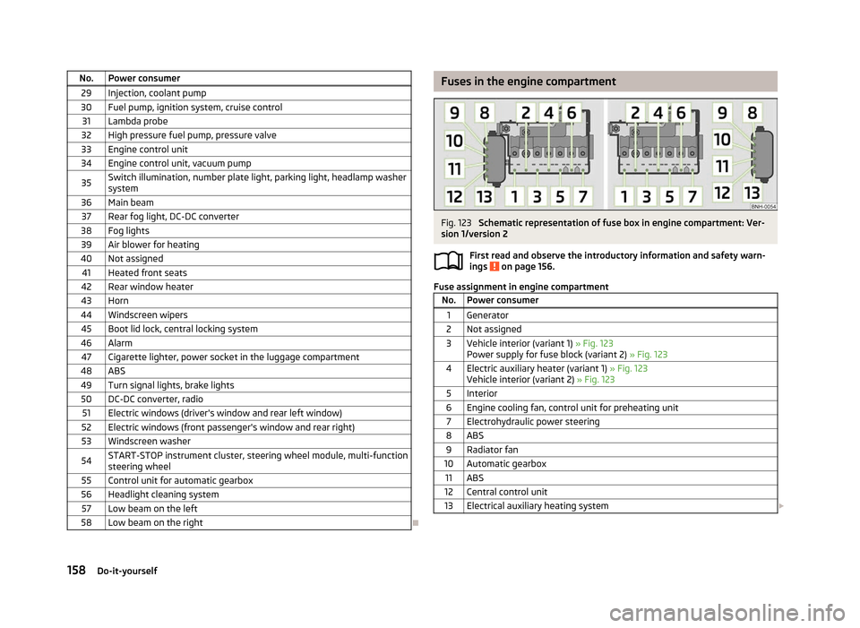
Fig. 123
Schematic representation of fuse box in engine compartment: Ver-
sion
1/version 2
First read and observe the introductory information and safety warn-
ings on page 156.
Fuse assignment in engine compartment
No. Power consumer
1 Generator
2 Not assigned
3 Vehicle interior (variant 1) » Fig. 123 Power supply for fuse block (variant
2) » Fig. 123
4 Electric auxiliary heater (variant 1) » Fig. 123 Vehicle interior (variant
2) » Fig. 123
5 Interior
6 Engine cooling fan, control unit for preheating unit 7 Electrohydraulic power steering
8 ABS 9 Radiator fan
10 Automatic gearbox 11 ABS
12 Central control unit
13 Electrical auxiliary heating system £ ä
158 Do-it-yourself
Page 161 of 180
Note
Fuses 1 - 7 are replaced by a specialist ŠKODA garage. ÐReplacing the fuses in the engine compartment
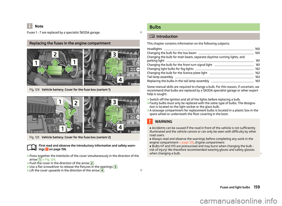
Fig. 124
Vehicle battery: Cover for the fuse box (variant 1) Fig. 125
Vehicle battery: Cover for the fuse box (variant 2)
First read and observe the introductory information and safety warn-
ings on page 156.
›
Press together the interlocks of the cover simultaneously in the direction of the
arrow 1
» Fig. 124.
› Push the cover in the direction of the arrow 2
.
› Use a flat screwdriver to release the fixtures in the openings 3
.
› Lift the cover upwards in the direction of the arrow 4
.
Ð
ä Bulbs
ä
Introduction
This chapter contains information on the following subjects:
Headlights 160
Changing the bulb for the low beam 160
Changing the bulb for main beam, separate daytime running lights, and
parking light 161
Changing the bulb for the front turn signal light 161
Changing light bulbs for fog lights 162
Changing the bulb for the licence plate light 162
Tail lamp assembly 163
Replacing the bulbs in the tail lamp assembly 163
Some manual skills are required to change a bulb. For this reason, if uncertain, we
recommend that bulbs are replaced by a ŠKODA specialist garage or other expert
help is sought.
› Switch off the ignition and all of the lights before replacing a bulb.
› Faulty bulbs must only be replaced with the same type of bulbs. The designa-
tion is located on the light socket or the glass bulb.
› A stowage compartment for replacement bulbs is located in a plastic box in the
spare wheel or underneath the floor covering in the boot. WARNING
■ Accidents can be caused if the road in front of the vehicle is not sufficiently
illuminated and the vehicle cannot or can only be seen with difficulty by other
road users.
■ Always read and observe the warnings before completing any work in the
engine compartment »
page 126, Engine compartment .
■ Bulbs H7 and H15 are pressurised and may burst when changing the bulb -
risk of injury! We therefore recommended wearing gloves and safety glasses
when changing a bulb. £
159
Fuses and light bulbs