heating SKODA RAPID 2012 1.G Owner's Manual
[x] Cancel search | Manufacturer: SKODA, Model Year: 2012, Model line: RAPID, Model: SKODA RAPID 2012 1.GPages: 180, PDF Size: 4.36 MB
Page 5 of 180
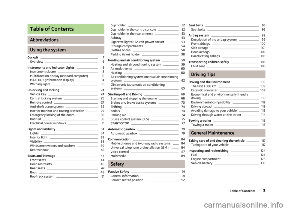
Table of Contents
Abbreviations
Using the system
Cockpit 7
Overview 6
Instruments and Indicator Lights 8
Instrument cluster 8
Multifunction display (onboard computer) 11
MAXI DOT (information display) 14
Warning lights 16
Unlocking and locking 24
Vehicle key 24
Central locking system 25
Remote control 27
Anti-theft alarm system 29
Interior monitor and towing protection 29
Emergency locking of the doors 30
Boot lid 30
Electrical power windows 31
Lights and visibility 34
Lights 34
Interior light 38
Visibility 39
Windscreen wipers and washers 39
Rear window 42
Seats and Stowage 44
Front seats 44
Head restraints 46
Rear seats 47
Boot 48
Roof rack system 51Cup holder 52
Cup holder in the centre console 52
Cup holder in the rear armrest 53
Ashtray 53
Cigarette lighter, 12-volt power socket 53
Storage compartments 54
Clothes hooks 58
Parking ticket holder 58
Heating and air conditioning system 59
Heating and air conditioning system 59
Air outlet vents 60
Heating 60
Air conditioning system (manual air conditioning
system) 62
Climatronic (automatic air conditioning
system) 65
Starting-off and Driving 68
Starting and stopping the engine 68
Brakes and brake assist systems 70
Shifting 74
pedals 74
Parking aid 74
Cruise control system (CCS) 75
START/STOP 77
Automatic gearbox 79
Automatic gearbox 79
Communication 84
Mobile phones and two-way radio systems 84
Universal telephone preinstallation GSM II 84
Voice control 87
Multimedia 89
Safety
Passive Safety 91
General information 91
Correct seated position 92Seat belts 95
Seat belts 95
Airbag system 99
Description of the airbag system 99
Front airbags 100
Side airbags 101
Head airbags 102
Deactivating airbags 103
Transporting children safely 105
Child seat 105
Driving Tips
Driving and the Environment 109
The first 1 500 km 109
Catalytic converter 109
Economical and environmentally friendly
driving 110
Environmental compatibility 112
Driving abroad 113
Avoiding damage to your vehicle 113
Driving through water on the street 114
Towing a trailer 115
Towing a trailer 115
General Maintenance
Taking care of and cleaning the vehicle 117
Taking care of your vehicle 117
Inspecting and replenishing 124
Fuel 124
Engine compartment 126
Vehicle battery 133
3
Table of Contents
Page 9 of 180
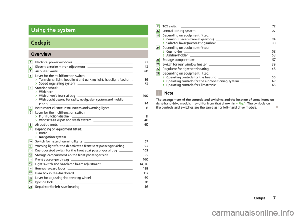
Using the system
Cockpit
Overview
Electrical power windows 32
Electric exterior mirror adjustment 42
Air outlet vents 60
Lever for the multifunction switch:
› Turn signal light, headlight and parking light, headlight flasher 36
› Speed regulating system 75
Steering wheel:
› With horn
› With driver’s front airbag 100
› With pushbuttons for radio, navigation system and mobile
phone 84
Instrument cluster: Instruments and warning lights 8
Lever for the multifunction switch:
› Multifunction display 11
› Windscreen wiper and wash system 40
Air outlet vents 60
Depending on equipment fitted:
› Radio
› Navigation system
Switch for hazard warning lights 37
Warning light for the deactivated front seat passenger airbag 103
Key-operated switch for the front seat passenger airbag 103
Storage compartment on the front passenger side 55
Front passenger airbag 100
Light switch and headlamp beam adjustment 34, 36
Bonnet release lever 128
Fuse box in the dashboard 157
Lever for adjusting the steering wheel 69
Ignition lock 70
Regulator for left seat heating 461
2
3
4
5
6
7
8
9
10
11
12
13
14
15
16
17
18
19
20 TCS switch 72
Central locking system 27
Depending on equipment fitted:
› Gearshift lever (manual gearbox) 74
› Selector lever (automatic gearbox) 80
Depending on equipment fitted:
› Cup holder 52
› Ashtray holder 53
Storage compartment 57
Switch for rear window heater 39
Regulator for right seat heating 46
Depending on equipment fitted:
› Operating controls for the heating 60
› Operating controls for the air conditioning system 62
› Operating controls for Climatronic 65
Note
The arrangement of the controls and switches and the location of some items on
right-hand drive models may differ from that shown in »
Fig. 1. The symbols on
the controls and switches are the same as for left-hand drive models. Ð 21
22
23
24
25
26
27
28
7
Cockpit
Page 11 of 180
Engine revolutions counter
First read and observe the introductory information and safety warn-
ings on page 8.
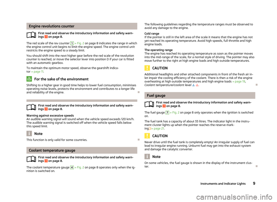
The red scale of the rev counter 1
» Fig. 2 on page 8 indicates the range in which
the engine control unit begins to limit the engine speed. The engine control unit
restricts the engine speed to a steady limit.
You should shift into the next higher gear before the red scale of the revolution
counter is reached, or move the selector lever into position D if your car is fitted
with an automatic gearbox.
To maintain the optimum motor speed, observe the gearshift indica-
tor » page 11. For the sake of the environment
Shifting to a higher gear in good time helps to lower fuel consumption, minimises
operating noise levels, protects the environment and contributes to a longer life
and reliability of the engine. ÐFirst read and observe the introductory information and safety warn-
ings
on page 8.
Warning against excessive speeds
An audible warning signal will sound when the vehicle speed exceeds 120
km/h.
The audible warning signal is switched off when the vehicle speed falls below
this speed limit. Note
This function is only valid for some countries. ÐCoolant temperature gauge
First read and observe the introductory information and safety warn-
ings on page 8.
The coolant temperature gauge 4
» Fig. 2 on page 8 operates only when the ig-
nition is switched on. ä
ä
ä The following guidelines regarding the temperature ranges must be observed to
avoid any damage to the engine.
Cold range
If the pointer is still in the left area of the scale it means that the engine has not
yet reached its operating temperature. Avoid high speeds, full throttle and high
engine loads.
The operating range
The engine has reached its operating temperature as soon as the pointer moves
into the mid-range of the scale, for a normal style of driving. The pointer may also
move further to the right at high engine loads and high outside temperatures. CAUTION
Additional headlights and other attached components in front of the fresh air in-
let impair the cooling efficiency of the coolant. There is then a risk of the engine
overheating at high outside temperatures and high engine loads »
page 19,
Coolant temperature/coolant level . Ð Fuel gauge
First read and observe the introductory information and safety warn-
ings on page 8.
The fuel gauge 7
» Fig. 2 on page 8 only operates when the ignition is switched
on.
The fuel tank has a capacity of about 55 litres. The indicator light in the instru-
ment cluster lights up when the pointer reaches the reserve mark-
ing » page 21 . CAUTION
Never drive until the fuel tank is completely empty! An irregular supply of fuel can
lead to irregular engine running. Unburnt fuel may get into the exhaust system
and damage the catalytic converter. Note
On some vehicles, the fuel gauge is shown in the display of the instrument clus-
ter. Ð
ä
9
Instruments and Indicator Lights
Page 34 of 180

WARNING
■ If the vehicle is locked from the outside, do not leave anybody in the vehicle
as it is not possible to open the windows from the inside in the event of an
emergency.
■ It is recommended to deactivate the electrical power windows in the rear
doors (safety pushbutton) S
» Fig. 17
on page 32 when children are being
transported on the rear seats. CAUTION
■ Keep the windows clean to ensure the correct functionality of the electric win-
dows. ■ In the event that the windows are frozen, first of all eliminate the
ice » page 120, De-icing windows and exterior mirrors and only then operate the
electrical power windows. Otherwise, the electrical power window mechanism
could be damaged. ■ When leaving the locked vehicle make sure that the windows are closed at all
times. Note
■ When driving always use the existing heating, air conditioning and ventilation
system for ventilating the interior of the vehicle. If the windows are opened, dust
as well as other dirt can get into the vehicle and in addition the wind noise is
more at certain speeds. ■ At high speeds, you should keep the windows closed to prevent unnecessarily
high fuel consumption. Ð Opening/closing the windows
Fig. 17
Buttons on the driver's door/in the rear doors
First read and observe the introductory information and safety warn-
ings on page 31.
The electrical power windows can only be operated when the ignition is switched
on.
Opening
›
A window is opened by pressing lightly on the respective button in the door.
The opening process stops when one releases the button.
› Additionally, the driver's window can be opened automatically (fully open) by
pressing the button to the stop. Renewed pressing of the button causes the
window to stop immediately.
Closing
› A window is closed through pulling lightly on the respective button in the door.
The closing process stops when one releases the button.
Buttons for the electrical power windows
Button for electrical power window of the driver's door
Button for electrical power window of the front passenger door
Safety pushbutton
Safety pushbutton
The buttons for electrical power windows in the rear doors can be deactivated by
pressing the safety pushbutton S
» Fig. 17. The buttons for the electrical power
windows in rear doors are activated again by pressing the safety pushbutton S
again.
£
ä
A
B
S
32
Using the system
Page 35 of 180

If the buttons for the rear doors are deactivated, the warning light
in the safe-
ty switch S
lights up.
Note
The window lift mechanism is equipped with protection against overheating. Re-
peated opening and closing of the window can cause this mechanism to over-
heat. If this happens, it will not be possible to operate the window for a short
time. You will be able to operate the window again as soon as the overheating
protection has cooled down. Ð 33
Unlocking and locking
Page 41 of 180
Visibility
Rear window heater
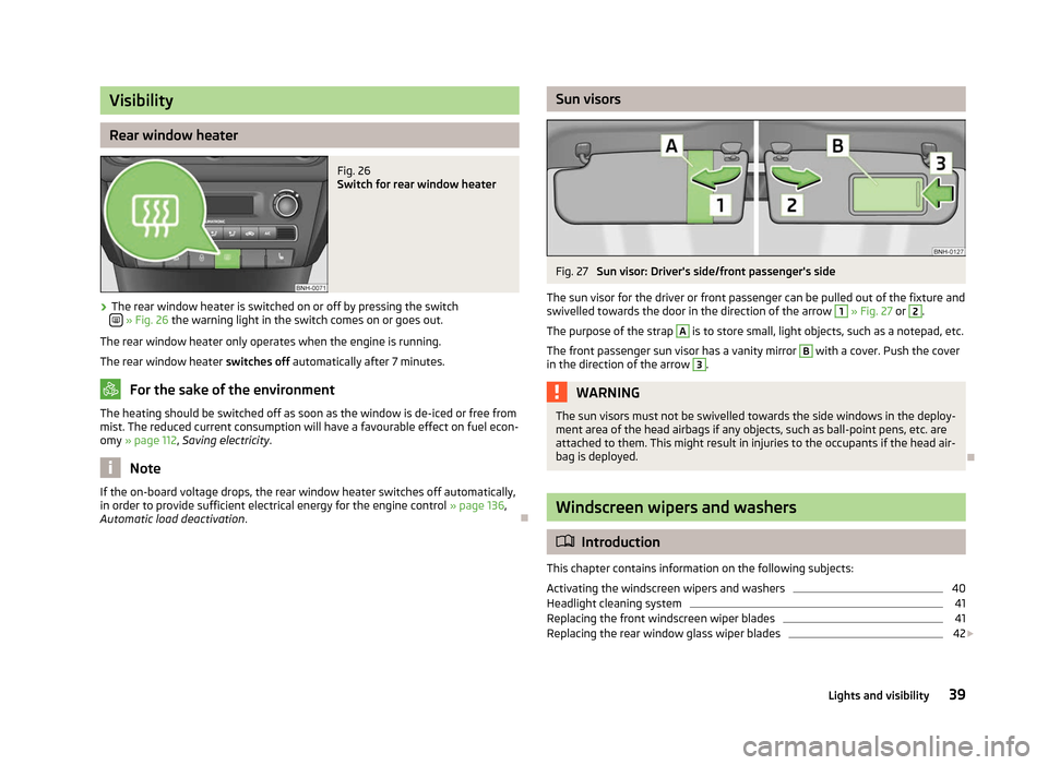
Fig. 26
Switch for rear window heater
› The rear window heater is switched on or off by pressing the switch
» Fig. 26
the warning light in the switch comes on or goes out.
The rear window heater only operates when the engine is running.
The rear window heater switches off automatically after 7 minutes. For the sake of the environment
The heating should be switched off as soon as the window is de-iced or free from
mist. The reduced current consumption will have a favourable effect on fuel econ-
omy »
page 112, Saving electricity .Note
If the on-board voltage drops, the rear window heater switches off automatically,
in order to provide sufficient electrical energy for the engine control »
page 136,
Automatic load deactivation . Ð Sun visors
Fig. 27
Sun visor: Driver's side/front passenger's side
The sun visor for the driver or front passenger can be pulled out of the fixture and
swivelled towards the door in the direction of the arrow 1
» Fig. 27
or 2
.
The purpose of the strap A
is to store small, light objects, such as a notepad, etc.
The front passenger sun visor has a vanity mirror B
with a cover. Push the cover
in the direction of the arrow 3
.
WARNING
The sun visors must not be swivelled towards the side windows in the deploy-
ment area of the head airbags if any objects, such as ball-point pens, etc. are
attached to them. This might result in injuries to the occupants if the head air-
bag is deployed. Ð Windscreen wipers and washers
ä
Introduction
This chapter contains information on the following subjects:
Activating the windscreen wipers and washers 40
Headlight cleaning system 41
Replacing the front windscreen wiper blades 41
Replacing the rear window glass wiper blades 42
£
39
Lights and visibility
Page 42 of 180
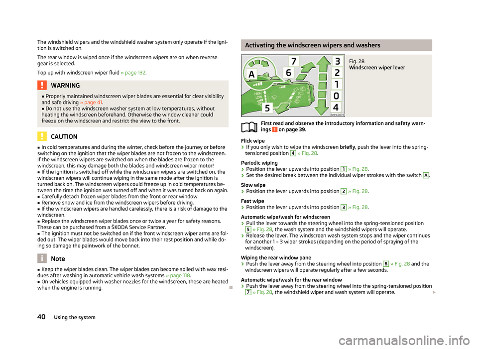
The windshield wipers and the windshield washer system only operate if the igni-
tion is switched on.
The rear window is wiped once if the windscreen wipers are on when reverse
gear is selected.
Top up with windscreen wiper fluid
» page 132.WARNING
■ Properly maintained windscreen wiper blades are essential for clear visibility
and safe driving » page 41. ■ Do not use the windscreen washer system at low temperatures, without
heating the windscreen beforehand. Otherwise the window cleaner could
freeze on the windscreen and restrict the view to the front. CAUTION
■ In cold temperatures and during the winter, check before the journey or before
switching on the ignition that the wiper blades are not frozen to the windscreen.
If the windscreen wipers are switched on when the blades are frozen to the
windscreen, this may damage both the blades and windscreen wiper motor!
■ If the ignition is switched off while the windscreen wipers are switched on, the
windscreen wipers will continue wiping in the same mode after the ignition is
turned back on. The windscreen wipers could freeze up in cold temperatures be-
tween the time the ignition was turned off and when it was turned back on again.
■ Carefully detach frozen wiper blades from the front or rear window.
■ Remove snow and ice from the windscreen wipers before driving.
■ If the windscreen wipers are handled carelessly, there is a risk of damage to the
windscreen.
■ Replace the windscreen wiper blades once or twice a year for safety reasons.
These can be purchased from a ŠKODA Service Partner.
■ The ignition must not be switched on if the front windscreen wiper arms are fol-
ded out. The wiper blades would move back into their rest position and while do-
ing so damage the paintwork of the bonnet. Note
■ Keep the wiper blades clean. The wiper blades can become soiled with wax resi-
dues after washing in automatic vehicle wash systems » page 118.
■ On vehicles equipped with washer nozzles for the windscreen, these are heated
when the engine is running. Ð Activating the windscreen wipers and washers
Fig. 28
Windscreen wiper lever
First read and observe the introductory information and safety warn-
ings on page 39.
Flick wipe
› If you only wish to wipe the windscreen
briefly, push the lever into the spring-
tensioned position 4
» Fig. 28
.
Periodic wiping
› Position the lever upwards into position 1
» Fig. 28
.
› Set the desired break between the individual wiper strokes with the switch A
.
Slow wipe
› Position the lever upwards into position 2
» Fig. 28
.
Fast wipe
› Position the lever upwards into position 3
» Fig. 28
.
Automatic wipe/wash for windscreen
› Pull the lever towards the steering wheel into the spring-tensioned position 5
» Fig. 28, the wash system and the windshield wipers will operate.
› Release the lever. The windscreen wash system stops and the wiper continues
for another 1 – 3 wiper strokes (depending on the period of spraying of the
windscreen).
Wiping the rear window pane
› Push the lever away from the steering wheel into position 6
» Fig. 28 and the
windscreen wipers will operate regularly after a few seconds.
Automatic wipe/wash for the rear window
› Push the lever away from the steering wheel into the spring-tensioned position 7
» Fig. 28, the windshield wiper and wash system will operate.
£
ä
40 Using the system
Page 44 of 180
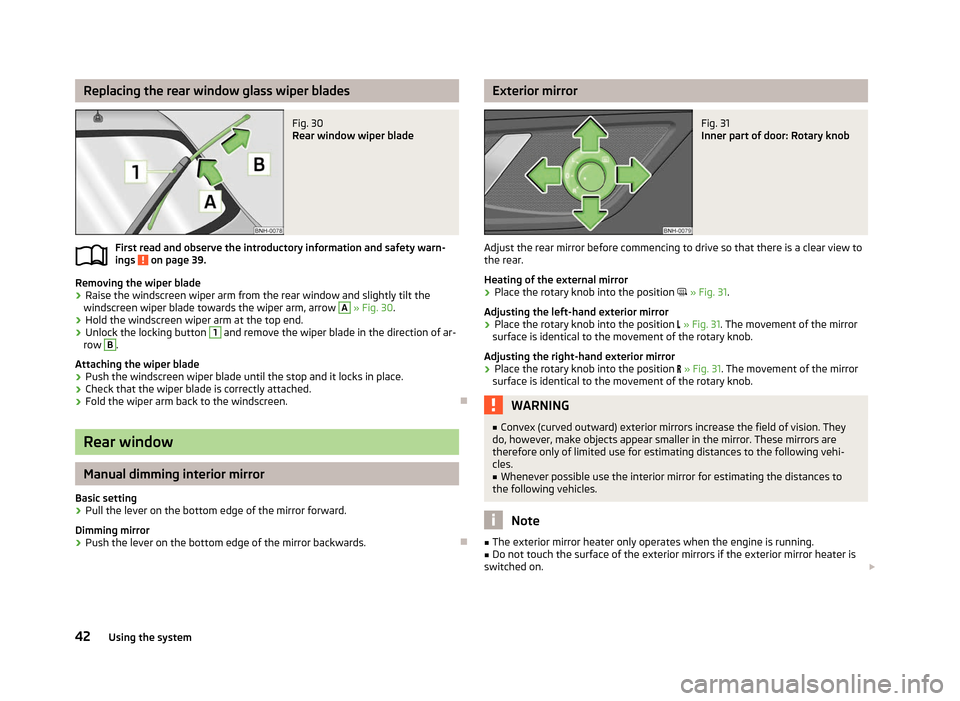
Replacing the rear window glass wiper blades
Fig. 30
Rear window wiper blade
First read and observe the introductory information and safety warn-
ings on page 39.
Removing the wiper blade
› Raise the windscreen wiper arm from the rear window and slightly tilt the
windscreen wiper blade towards the wiper arm, arrow A
» Fig. 30
.
› Hold the windscreen wiper arm at the top end.
› Unlock the locking button 1
and remove the wiper blade in the direction of ar-
row B
.
Attaching the wiper blade
› Push the windscreen wiper blade until the stop and it locks in place.
› Check that the wiper blade is correctly attached.
› Fold the wiper arm back to the windscreen. ÐRear window
Manual dimming interior mirror
Basic setting
› Pull the lever on the bottom edge of the mirror forward.
Dimming mirror
› Push the lever on the bottom edge of the mirror backwards. Ð
ä Exterior mirror
Fig. 31
Inner part of door: Rotary knob
Adjust the rear mirror before commencing to drive so that there is a clear view to
the rear.
Heating of the external mirror
› Place the rotary knob into the position
» Fig. 31.
Adjusting the left-hand exterior mirror
› Place the rotary knob into the position
» Fig. 31. The movement of the mirror
surface is identical to the movement of the rotary knob.
Adjusting the right-hand exterior mirror
› Place the rotary knob into the position
» Fig. 31. The movement of the mirror
surface is identical to the movement of the rotary knob. WARNING
■ Convex (curved outward) exterior mirrors increase the field of vision. They
do, however, make objects appear smaller in the mirror. These mirrors are
therefore only of limited use for estimating distances to the following vehi-
cles.
■ Whenever possible use the interior mirror for estimating the distances to
the following vehicles. Note
■ The exterior mirror heater only operates when the engine is running.
■ Do not touch the surface of the exterior mirrors if the exterior mirror heater is
switched on. £
42 Using the system
Page 46 of 180
Seats and Stowage
Front seats
ä
Introduction
This chapter contains information on the following subjects:
Adjusting the front seats 45
Front armrest with storage compartment 45
Front seat heating 46
The driver's seat should be adjusted in such a way that the pedals can be fully
pressed to the floor with slightly bent legs.
The seat backrest on the driver's seat should be adjusted in such a way that the
upper point of the steering wheel can be easily reached with slightly bent arms.
Correct adjustment of the seats is particularly important for:
› safely and quickly reaching the controls;
› a relaxed, fatigue-free body position;
› achieving the maximum protection offered by the seat belts and the airbag
system. WARNING
■ Only adjust the driver's seat when the vehicle is stationary – risk of accident!
■ Caution when adjusting the seat! You may suffer injuries or bruises as a re-
sult of adjusting the seat without paying proper attention.
■ The seat backrests must not be angled too far back when driving otherwise
this will affect proper operation of the seat belts and of the airbag system –
risk of injury!
■ Never carry more people than the number of seats in the vehicle.
■ Each occupant must correctly fasten the seat belt belonging to the seat.
Children must be fastened » page 105, Transporting children safely with a
suitable restraint system. WARNING (Continued)
■ The front seats and the head restraints must always be adjusted to match
the body size of the seat occupant as well as the seat belts must always be
correctly fastened in order to provide an optimal protection for you and your
occupants.
■ Always keep your feet in the footwell when the car is being driven – never
place your feet on the instrument panel, out of the window or on the surfaces
of the seats. This is particularly important for the front seat passenger. You
will be exposed to increased risk of injury if it becomes necessary to apply the
brake or in the event of an accident. If an airbag is deployed, you may suffer
fatal injuries when adopting an incorrect seated position!
■ It is important for the driver and front passenger to maintain a distance of at
least 25 cm from the steering wheel or dash panel. Not maintaining this mini-
mum distance will mean that the airbag system will not be able to properly
protect you – hazard!
■ Ensure that there are no objects in the footwell as they may get caught be-
hind the pedals when driving or applying the braking. You would then no lon-
ger be able to operate the clutch, brake or accelerate. ■ Do not transport any objects on the front passenger seat except objects
(e.g. child safety seat) provided for this purpose – risk of accident! Note
After a certain time, play can develop within the adjustment mechanism of the
backrest angle. Ð
44 Using the system
Page 48 of 180
Front seat heating
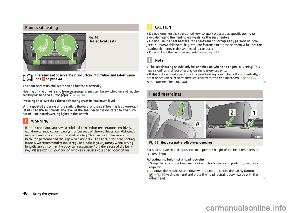
Fig. 34
Heated front seats
First read and observe the introductory information and safety warn-
ings on page 44.
The seat backrests and seats can be heated electrically.
Heating on the driver's and front passenger's seat can be switched on and regula-
ted by pressing the button or
» Fig. 34.
Pressing once switches the seat heating on at its maximum level.
With repeated pressing of the switch, the level of the seat heating is down-regu-
lated up to the switch-off. The level of the seat heating is indicated by the num-
ber of illuminated warning lights in the switch. WARNING
If, as an occupant, you have a subdued pain and/or temperature sensitivity,
e.g. through medication, paralysis or because of chronic illness (e.g. diabetes),
we recommend not to use the seat heating. This can lead to burns on the
back, the posterior and the legs which are difficult to heal. If the seat heating
is used, we recommend to make regular breaks in your journey when driving
long distances, so that the body can recuperate from the stress of the jour-
ney. Please consult your doctor, who can evaluate your specific condition.
ä CAUTION
■ Do not kneel on the seats or otherwise apply pressure at specific points to
avoid damaging the heating elements for the seat heaters.
■ Do not use the seat heaters if the seats are not occupied by persons or if ob-
jects, such as a child seat, bag, etc., are fastened or stored on them. A fault of the
heating elements in the seat heating can occur.
■ Do not clean the seats using moisture » page 122. Note
■ The seat heating should only be switched on when the engine is running. This
has a significant effect of saving on the battery capacity. ■ If the on-board voltage drops, the seat heating is switched off automatically, in
order to provide sufficient electrical energy for the engine control » page 136,
Automatic load deactivation . Ð Head restraints
Fig. 35
Head restraint: adjusting/removing
For sports seats, it is not possible to adjust the height of the head restraints or
remove them.
Adjusting the height of a head restraint
› Grasp the side of the head restraint with both hands and push it upwards as
required.
› To move the head restraint downwards, press and hold the safety button A
» Fig. 35 with one hand and press the head restraint downwards with the
other hand. £
46 Using the system