display SKODA RAPID 2013 1.G Owner's Guide
[x] Cancel search | Manufacturer: SKODA, Model Year: 2013, Model line: RAPID, Model: SKODA RAPID 2013 1.GPages: 226, PDF Size: 15.16 MB
Page 31 of 226
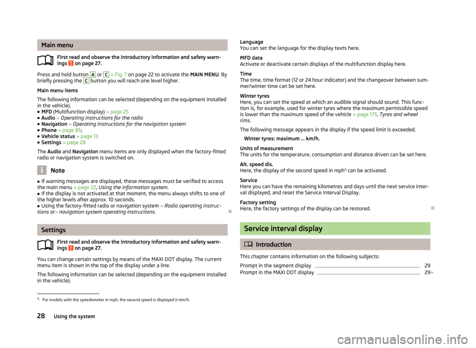
Main menuFirst read and observe the introductory information and safety warn-
ings
on page 27.
Press and hold button
A
or
C
» Fig. 7 on page 22 to activate the MAIN MENU. By
briefly pressing the
C
button you will reach one level higher.
Main menu items
The following information can be selected (depending on the equipment installed in the vehicle).
■ MFD (Multifunction display) » page 25
■ Audio » Operating instructions for the radio
■ Navigation » Operating instructions for the navigation system
■ Phone » page 85 ;
■ Vehicle status » page 13
■ Settings » page 28
The Audio and Navigation menu items are only displayed when the factory-fitted
radio or navigation system is switched on.
Note
■ If warning messages are displayed, these messages must be verified to access
the main menu » page 22, Using the information system .■
If the display is not activated at that moment, the menu always shifts to one of
the higher levels after approx. 10 seconds.
■
Using the factory-fitted radio or navigation system » Radio operating instruc-
tions or» navigation system operating instructions .
Settings
First read and observe the introductory information and safety warn-
ings
on page 27.
You can change certain settings by means of the MAXI DOT display. The current
menu item is shown in the top of the display under a line.
The following information can be selected (depending on the equipment installed in the vehicle).
Language
You can set the language for the display texts here.
MFD data
Activate or deactivate certain displays of the multifunction display here.
Time
The time, time format (12 or 24 hour indicator) and the changeover between sum- mer/winter time can be set here.
Winter tyres
Here, you can set the speed at which an audible signal should sound. This func- tion is, for example, used for winter tyres where the maximum permissible speed
is lower than the maximum speed of the vehicle » page 175, Tyres and wheel
rims .
The following message appears in the display if the speed limit is exceeded. Winter tyres: maximum ... km/h.
Units of measurement
The units for the temperature, consumption and distance driven can be set here.
Alt. speed dis.
Here, the display of the second speed in mph 1)
can be activated.
Service
Here you can have the remaining kilometres and days until the next service inter-
val displayed, and reset the Service Interval Display.
Factory setting
Here, the factory settings of the display can be restored.
Service interval display
Introduction
This chapter contains information on the following subjects:
Prompt in the segment display
29
Prompt in the MAXI DOT display
29
1)
For models with the speedometer in mph, the second speed is displayed in km/h.
28Using the system
Page 32 of 226
Before the next service interval is reached, a message concerning the kilometres
and days remaining until the next service is due is shown for about 10 seconds
after the ignition is switched on. Alternatively, this information can be displayed
manually at any time if required.
The kilometre indicator or the days indicator reduces in steps of 100 km or, where
applicable, days until the service due date is reached.
Note
■ Information is retained in the Service Interval Display even after the vehicle bat-
tery is disconnected.■
If the instrument cluster is exchanged after a repair, the correct values must be
entered in the counter for the Service Interval Display. This work is carried out by a specialist garage.
■
In certain national versions, the displays appear with Imperial values.
■
For more information on the service intervals, see » page 147, Service intervals .
Prompt in the segment display
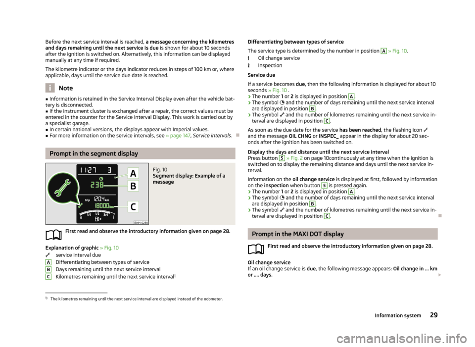
Fig. 10
Segment display: Example of a
message
First read and observe the introductory information given on page 28.
Explanation of graphic » Fig. 10
service interval due
Differentiating between types of service Days remaining until the next service interval
Kilometres remaining until the next service interval 1)
ABCDifferentiating between types of service
The service type is determined by the number in position A
» Fig. 10 .
Oil change service
Inspection
Service due
If a service becomes due, then the following information is displayed for about 10
seconds » Fig. 10 .
› The number
1 or 2 is displayed in position
A
.
› The symbol
and the number of days remaining until the next service interval
are displayed in position
B
.
› The symbol
and the number of kilometres remaining until the next service in-
terval are displayed in position
C
.
As soon as the due date for the service has been reached, the flashing icon
and the message OIL CHNG or INSPEC_ appear in the display for about 20 sec-
onds after the ignition has been switched on.
Display the days and distance until the next service interval
Press button
5
» Fig. 2 on page 10continuously at any time when the ignition is
switched on to display the remaining distance and days until the next service in- terval.
Information on the oil change service is displayed at first, followed by information
on the inspection when button
5
is pressed again.
› The number
1 or 2 is displayed in position
A
.
› The symbol
and the number of days remaining until the next service interval
are displayed in position
B
.
› The symbol
and the number of kilometres remaining until the next service in-
terval are displayed in position
C
.
Prompt in the MAXI DOT display
First read and observe the introductory information given on page 28.
Oil change service
If an oil change service is due, the following message appears: Oil change in ... km
or .... days.
1)
The kilometres remaining until the next service interval are displayed instead of the odometer.
29Information system
Page 33 of 226
As soon as the service interval date has been reached, the message Oil change
now! appears once the ignition has been switched on.
Inspection
If an inspection is due, the following message appears: Inspection in ... km or ...
days.
As soon as the service interval date has been reached, the message Inspection
now! appears once the ignition has been switched on.
Displaying the distance and days until the next service interval You can view the remaining distance and days until the next service appointmentat any time when the ignition is switched on by going to the Settings menu
item » page 28 or from the vehicle status in the main menu of the Maxi DOTdis-
play. » page 28
The following message is displayed for 10 seconds. Oil change ... km / ... days
Inspection ... km / ... days
30Using the system
Page 34 of 226
Unlocking and opening
Unlocking and locking
Introduction
This chapter contains information on the following subjects:
Vehicle key
32
Unlocking/locking with the key
32
Unlocking/locking with the remote control
33
Safe securing system
33
Individual settings
34
Locking/unlocking the vehicle from the inside
34
Child safety lock
35
Opening/closing a door
35
Your car is equipped with a central locking system.
The central locking system allows you to lock and unlock all doors, the fuel filler
flap 1)
and tailgate at the same time.
The safe securing system » page 33 is integrated in the central locking system.
Once the car is locked from the outside, the door locks are automatically blocked
by the safe securing system »
.
The following is true after unlocking
› The doors, the boot lid and the fuel filler flap 1)
are unlocked.
› The interior light, which is switched by the door contact, comes on.
› The safe securing system is switched off.
› The indicator light in the driver door stops flashing.
› The anti-theft alarm system is deactivated 2)
.
The following is true after locking
› The doors, the boot lid and the fuel filler flap 1)
are locked.
› The interior lights connected over the door contact go off.
› The safe securing system is switched on.
›
The warning light in the driver door begins flashing.
› The anti-theft alarm system is activated 2)
.
Displaying an error
If the indicator light in the driver's door initially flashes quickly for around 2 sec-
onds, and then lights up for 30 seconds without interruption before flashing
again slowly, you will need to seek the assistance of a specialist garage.WARNING■ If the car is locked and the safe securing system activated, no people must
remain in the car as it will then not be possible to either unlock a door or open
a window from the inside. The locked doors make it more difficult for rescuers
to get into the vehicle in an emergency – risk to life!■
Locked doors prevent unwanted entry into the vehicle from outside, for ex-
ample at road crossings.
Note
■ In the event of an accident in which the airbags are deployed, the locked doors
are automatically unlocked in order to enable rescuers to gain access to the vehi- cle.■
Only the driver's door can be unlocked or locked using the key if the central
locking system fails » page 32. The other doors and the tailgate can be emer-
gency locked or emergency released. ■ Emergency locking of the door » page 194.
■ Emergency unlocking of the boot lid » page 194.
1)
Applies to vehicles with a lockable fuel filler cap.
2)
Applies to vehicles with an anti-theft alarm system.
31Unlocking and opening
Page 36 of 226
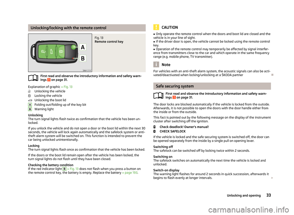
Unlocking/locking with the remote controlFig. 13
Remote control key
First read and observe the introductory information and safety warn-
ings on page 31.
Explanation of graphic » Fig. 13
Unlocking the vehicle
Locking the vehicle
Unlocking the boot lid
Folding out/folding up of the key bit Warning light
Unlocking
The turn signal lights flash twice as confirmation that the vehicle has been un-
locked.
If you unlock the vehicle and do not open a door or the boot lid within the next 30 seconds, the vehicle will lock again automatically and the safelock system or anti-
theft alarm system will be switched on. This function is intended to prevent the car being unlocked unintentionally.
Locking
The turn signal lights flash once as confirmation that the vehicle has been locked.
If the doors or the boot lid remain open after the vehicle has been locked, the
turn signal lights do not flash until they have been closed.
Checking the battery condition
If the red indicator light
B
» Fig. 13 does not flash when you press a button on
the remote control key, the battery is empty. Replace the battery » page 193.
ABCAUTION■
Only operate the remote control when the doors and boot lid are closed and the
vehicle is in your line of sight.■
If the driver door is open, the vehicle cannot be locked using the remote control
key.
■
Operation of the remote control may temporarily be affected by signal interfer-
ence from transmitters close to the car and which operate in the same frequency
range (e.g. mobile phone, TV transmitter).
Note
For vehicles with an anti-theft alarm system, the acoustic signals can also be acti-
vated/deactivated when locking/unlocking at a ŠKODA partner
Safe securing system
First read and observe the introductory information and safety warn-
ings
on page 31.
The door locks are blocked automatically if the vehicle is locked from the outside.
Afterwards, it is not possible to open the doors with the door handle either from
the inside or from the outside.
This fact is pointed out by the following message on the display of the instrument
cluster after switching off the ignition.
Check deadlock! Owner's manual!CHECK SAFELOCK
If the vehicle is locked and the safe securing system is switched off, the door can be opened separately from the inside by a single pull on opening lever.
Switching off
The safelock can be switched off by locking twice within 2 seconds.
Switching on
The safelock switches on automatically the next time the vehicle is locked and
unlocked.
Switch-on display
The warning light flashes for around 2 seconds in quick succession, afterwards it
begins to flash evenly at longer intervals.
33Unlocking and opening
Page 37 of 226
Switch-off display
The indicator light in the driver door flashes for about 2 seconds fast, goes out
and starts to flash at longer intervals after about 30 seconds.WARNINGIf the car is locked and the safe securing system activated, no people must re- main in the car as it will then not be possible to either unlock a door or open a
window from the inside. The locked doors make it more difficult for rescuers
to get into the vehicle in an emergency – risk to life!
Note
This function only applies to certain countries.
Individual settings
First read and observe the introductory information and safety warn-
ings
on page 31.
Opening a single door
This function makes it possible to only unlock the driver's door. The other doors
remain locked and are only unlocked when the command is repeated.
Automatic locking/unlocking
All doors are locked from a speed of around 15 km/h. The button in the handle of
the boot lid is deactivated.
If the ignition key is withdrawn, the car is then automatically unlocked again. In addition, it is possible for the driver or front passenger to unlock the car by press- ing the central locking button
.
The vehicle doors can be unlocked and opened at any time by pulling once on the door opening lever.
Note
Individual settings can be carried out in a specialist workshop.
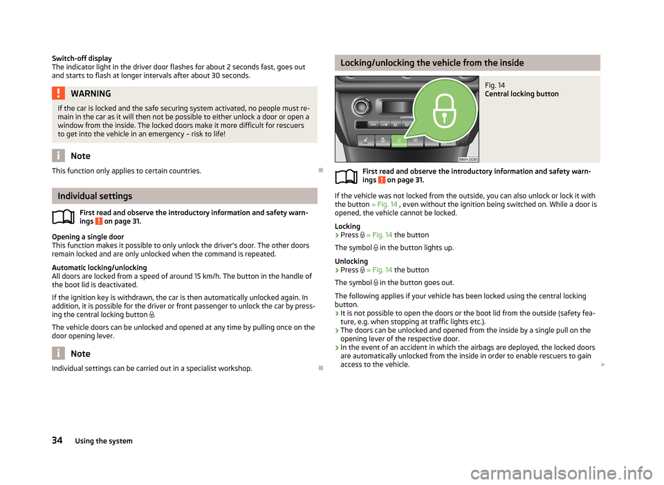
Locking/unlocking the vehicle from the insideFig. 14
Central locking button
First read and observe the introductory information and safety warn-ings on page 31.
If the vehicle was not locked from the outside, you can also unlock or lock it with
the button » Fig. 14 , even without the ignition being switched on. While a door is
opened, the vehicle cannot be locked.
Locking
›
Press
» Fig. 14 the button
The symbol
in the button lights up.
Unlocking
›
Press
» Fig. 14 the button
The symbol
in the button goes out.
The following applies if your vehicle has been locked using the central locking button.
› It is not possible to open the doors or the boot lid from the outside (safety fea-
ture, e.g. when stopping at traffic lights etc.).
› The doors can be unlocked and opened from the inside by a single pull on the
opening lever of the respective door.
› In the event of an accident in which the airbags are deployed, the locked doors
are automatically unlocked from the inside in order to enable rescuers to gain access to the vehicle.
34Using the system
Page 44 of 226
Lights and visibility
Lights
Introduction
This chapter contains information on the following subjects:
Parking light and low beam
41
Daytime running lights(DAY LIGHT)
42
Turn signal and main beam
43
Fog lights
43
Fog lights with CORNER function
43
Rear fog light
44
Hazard warning light system
44
Parking light
45
Unless otherwise stated, the lights only work when the ignition is switched on.
On models fitted with right-hand steering, the position of some of the controls
differs from that shown in » Fig. 21 on page 41. The symbols which mark the po-
sitions of the controls are identical.
WARNING■ The activation of the lights should only be undertaken in accordance with
national legal requirements.■
The driver is always responsible for the correct settings and use of the
lights.
■
Never drive with only the side lights on! The side lights are not bright
enough to light up the road sufficiently in front of you or to be seen by other oncoming traffic. Therefore always switch on the low beam when it is dark or if visibility is poor.
NoteThe headlights may mist up temporarily. When the driving lights are switched on,
the light outlet surfaces are free from mist after a short period, although the
headlight lenses may still be misted up in the peripheral areas. This mist has no
influence on the life of the lighting system.
Parking light and low beam
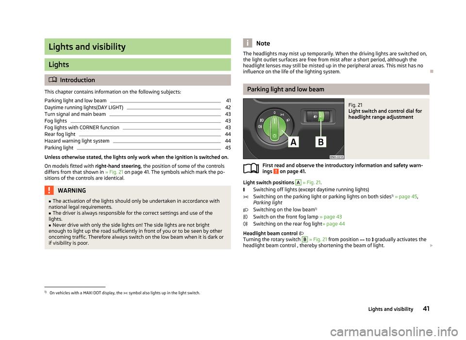
Fig. 21
Light switch and control dial for
headlight range adjustment
First read and observe the introductory information and safety warn-
ings on page 41.
Light switch positions
A
» Fig. 21 .
Switching off lights (except daytime running lights) Switching on the parking light or parking lights on both sides 1)
» page 45 ,
Parking light
Switching on the low beam 1)
Switch on the front fog lamp » page 43
Switching on the rear fog light » page 44
Headlight beam control
Turning the rotary switch
B
» Fig. 21 from position
to
gradually activates the
headlight beam control , thereby shortening the beam of light.
1)
On vehicles with a MAXI DOT display, the
symbol also lights up in the light switch.
41Lights and visibility
Page 48 of 226
Parking lightFirst read and observe the introductory information and safety warn-
ings
on page 41.
Parking light switching on
›
Switch off the ignition.
›
Place the control lever into position
A
or
B
as far as it can go » Fig. 22 on
page 43 - the parking light on the right/left-hand side of the vehicle is switched
on.
Switching on the side light on both sides
›
Turn the light switch
A
to position » Fig. 21 on page 41 and lock the vehicle.
Note
■
The parking light can only be activated if the ignition is switched off.■If the right or left turn signal light has been switched on and the ignition is
switched off, the parking light is not automatically switched on.■
On vehicles with a MAXI DOT display, the symbol in the light switch also
lights up when the two-sided parking light is switched on.
Interior lighting
Front interior lighting – version 1
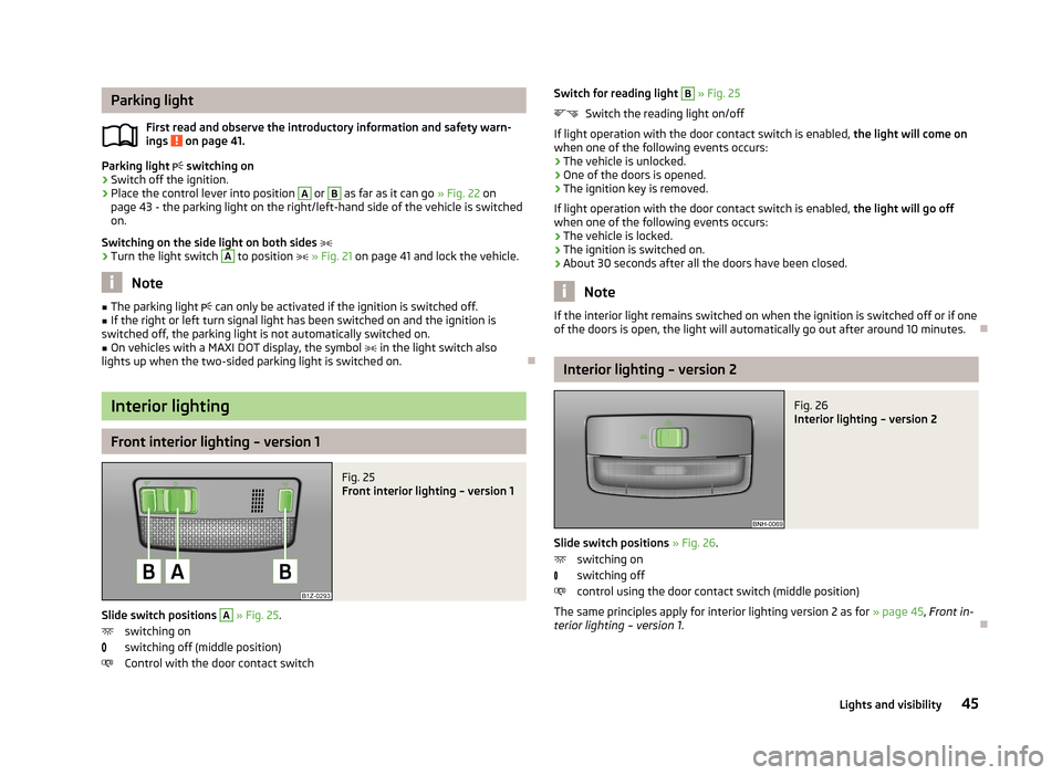
Fig. 25
Front interior lighting – version 1
Slide switch positions
A
» Fig. 25 .
switching on
switching off (middle position)
Control with the door contact switch
Switch for reading light B » Fig. 25
Switch the reading light on/off
If light operation with the door contact switch is enabled, the light will come on
when one of the following events occurs:
› The vehicle is unlocked.
› One of the doors is opened.
› The ignition key is removed.
If light operation with the door contact switch is enabled, the light will go off
when one of the following events occurs:
› The vehicle is locked.
› The ignition is switched on.
› About 30 seconds after all the doors have been closed.
Note
If the interior light remains switched on when the ignition is switched off or if one
of the doors is open, the light will automatically go out after around 10 minutes.
Interior lighting – version 2
Fig. 26
Interior lighting – version 2
Slide switch positions » Fig. 26 .
switching on
switching off
control using the door contact switch (middle position)
The same principles apply for interior lighting version 2 as for » page 45, Front in-
terior lighting – version 1 .
45Lights and visibility
Page 85 of 226
Climatronic (automatic air conditioning system)
Introduction
This chapter contains information on the following subjects:
Control elements
82
automatic mode
83
Switching the cooling system on/off
83
Setting the temperature
83
recirculated air mode
83
Controlling blower
84
Defrosting windscreen
84
The Climatronic in automatic mode ensures the best-possible setting of the tem-
perature of the outflowing air, the blower stage and air distribution.
The system also takes sunlight into account, which eliminates the need to alterthe settings manually.
The cooling system only operates if the following conditions are met. The cooling system is switched on » page 82, Control elements .
The engine is running.
The outside temperature is above approx. +2 °C.
The cooling system is switched off at excessive coolant temperatures in order to guarantee a cooling effect when the engine is under a high load.
Note
We recommend that you have Climatronic cleaned by a specialist garage once ev-
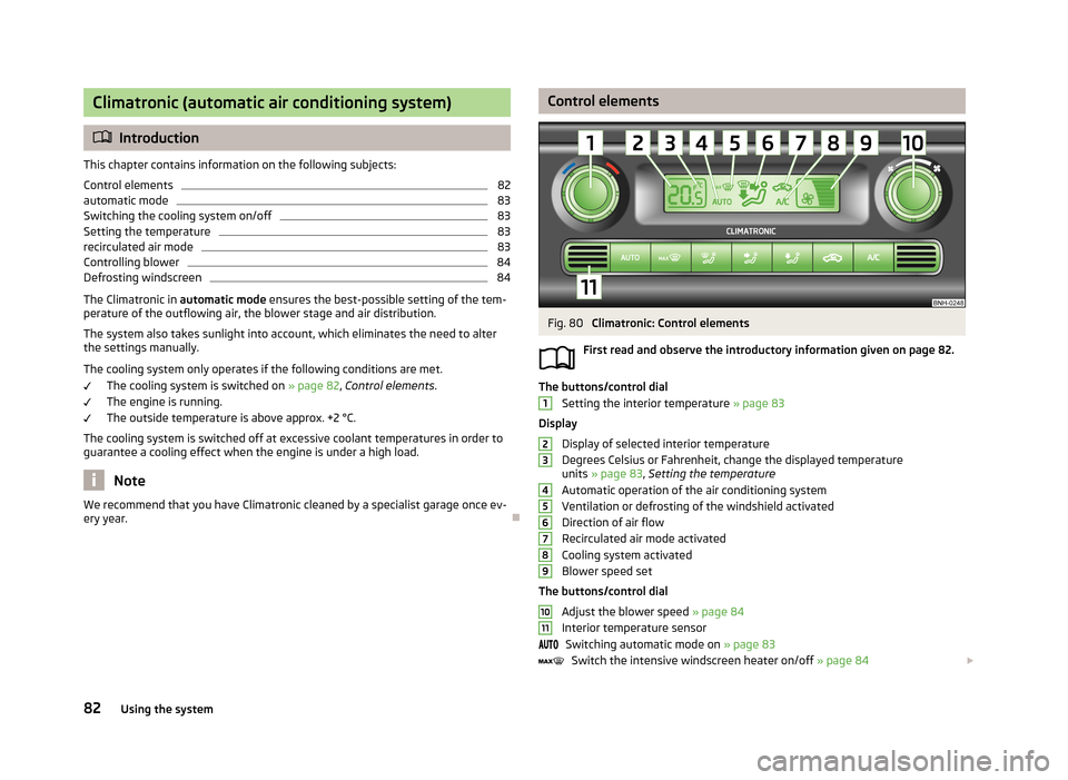
ery year.Control elementsFig. 80
Climatronic: Control elements
First read and observe the introductory information given on page 82.
The buttons/control dial Setting the interior temperature » page 83
Display
Display of selected interior temperature
Degrees Celsius or Fahrenheit, change the displayed temperature units » page 83 , Setting the temperature
Automatic operation of the air conditioning system Ventilation or defrosting of the windshield activated
Direction of air flow
Recirculated air mode activated
Cooling system activated
Blower speed set
The buttons/control dial Adjust the blower speed » page 84
Interior temperature sensor Switching automatic mode on » page 83
Switch the intensive windscreen heater on/off » page 84
123456789101182Using the system
Page 86 of 226
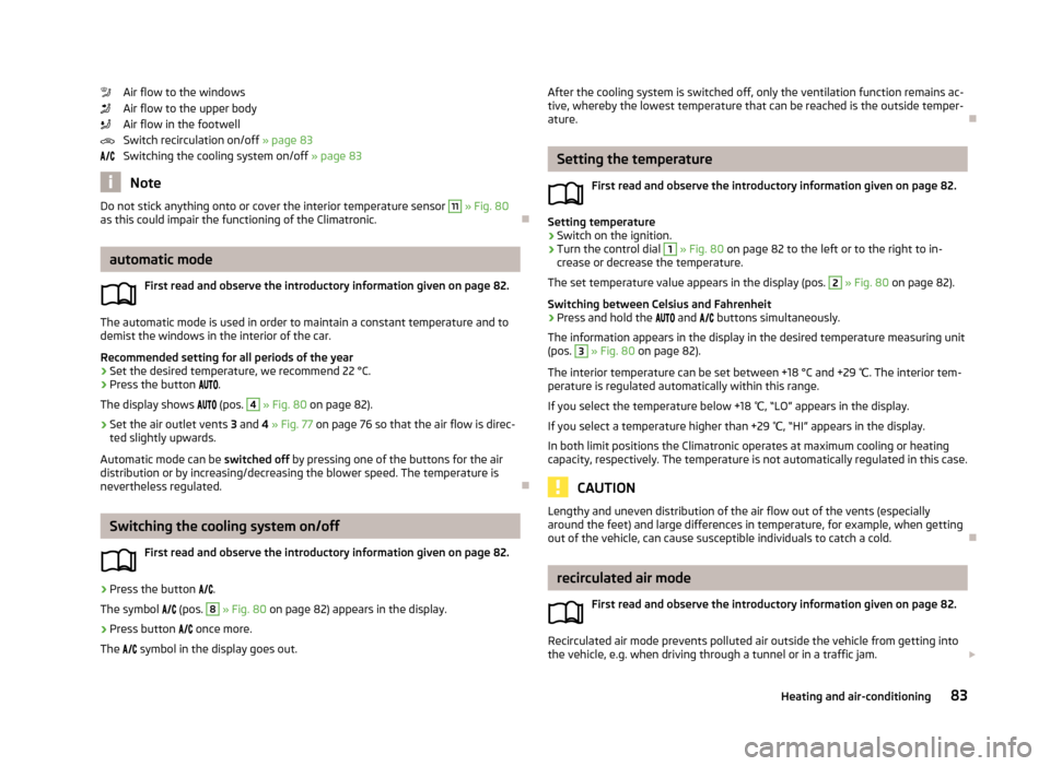
Air flow to the windows
Air flow to the upper body
Air flow in the footwell
Switch recirculation on/off » page 83
Switching the cooling system on/off » page 83
Note
Do not stick anything onto or cover the interior temperature sensor 11 » Fig. 80
as this could impair the functioning of the Climatronic.
automatic mode
First read and observe the introductory information given on page 82.
The automatic mode is used in order to maintain a constant temperature and to
demist the windows in the interior of the car.
Recommended setting for all periods of the year
›
Set the desired temperature, we recommend 22 °C.
›
Press the button
.
The display shows
(pos.
4
» Fig. 80 on page 82).
›
Set the air outlet vents 3 and 4 » Fig. 77 on page 76 so that the air flow is direc-
ted slightly upwards.
Automatic mode can be switched off by pressing one of the buttons for the air
distribution or by increasing/decreasing the blower speed. The temperature is
nevertheless regulated.
Switching the cooling system on/off
First read and observe the introductory information given on page 82.
›
Press the button
.
The symbol
(pos.
8
» Fig. 80 on page 82) appears in the display.
›
Press button
once more.
The
symbol in the display goes out.
After the cooling system is switched off, only the ventilation function remains ac-
tive, whereby the lowest temperature that can be reached is the outside temper- ature.
Setting the temperature
First read and observe the introductory information given on page 82.
Setting temperature
›
Switch on the ignition.
›
Turn the control dial
1
» Fig. 80 on page 82 to the left or to the right to in-
crease or decrease the temperature.
The set temperature value appears in the display (pos.
2
» Fig. 80 on page 82).
Switching between Celsius and Fahrenheit
›
Press and hold the
and
buttons simultaneously.
The information appears in the display in the desired temperature measuring unit
(pos.
3
» Fig. 80 on page 82).
The interior temperature can be set between +18 °C and +29 ℃. The interior tem-
perature is regulated automatically within this range.
If you select the temperature below +18 ℃, “LO” appears in the display.
If you select a temperature higher than +29 ℃, “HI” appears in the display.
In both limit positions the Climatronic operates at maximum cooling or heating
capacity, respectively. The temperature is not automatically regulated in this case.
CAUTION
Lengthy and uneven distribution of the air flow out of the vents (especially
around the feet) and large differences in temperature, for example, when getting
out of the vehicle, can cause susceptible individuals to catch a cold.
recirculated air mode
First read and observe the introductory information given on page 82.
Recirculated air mode prevents polluted air outside the vehicle from getting into
the vehicle, e.g. when driving through a tunnel or in a traffic jam.
83Heating and air-conditioning