stop start SKODA RAPID 2013 1.G Owner's Manual
[x] Cancel search | Manufacturer: SKODA, Model Year: 2013, Model line: RAPID, Model: SKODA RAPID 2013 1.GPages: 226, PDF Size: 15.16 MB
Page 6 of 226
Table of Contents
Materials defect liability and ŠKODA warranty for
new cars5
Mobility warranty and ŠKODA extended
warranty
6
Abbreviations
Using the system
Cockpit
9
Overview
8
Instruments and Indicator Lights
10
Instrument cluster
10
Indicator lights
14
Information system
22
Driver information system
22
Multifunction display (MFD)
25
MAXI DOT display
27
Service interval display
28
Unlocking and opening
31
Unlocking and locking
31
Anti-theft alarm system
36
Luggage compartment lid
37
Electrical power windows
38
Lights and visibility
41
Lights
41
Interior lighting
45
Visibility
46
Windscreen wipers and washers
48
Rear mirror
49Seats and useful equipment52Adjusting the seats52
Seat features
54
Practical equipment
56
Luggage compartment
64
Variable loading floor in the luggage
compartment (Rapid Spaceback)
70
Roof rack system
74
Heating and air-conditioning
76
Heating, ventilation, cooling
76
Heating
77
Air conditioning system (manual air conditioning system)
79
Climatronic (automatic air conditioning
system)
82
Communication and multimedia
85
Universal telephone installation GSM II
85
Voice control
90
Multimedia
92
Driving
Starting-off and Driving
96
Steering
96
Starting and stopping the engine
97
Brakes
99
Manual gear changing and pedals
101
Automatic transmission
101
Running in
104
Economical driving and environmental
sustainability
105
Avoiding damage to your vehicle
109
Driving abroad
110
Assist systems
111
Brake assist systems
111
Parking aid
113Cruise Control System114START-STOP116
Towing a trailer
119
Towing device
119
Trailer
123
Safety
Passive Safety
126
General information
126
Correct seated position
127
Seat belts
130
Using seat belts
130
Inertia reels and belt tensioners
133
Airbag system
135
Description of the airbag system
135
Airbag overview
136
Deactivating airbags
139
Transporting children safely
142
Child seat
142
Fastening systems
145
General Maintenance
Vehicle care
147
Service intervals
147
Service work, adjustments and technical alterations
149
Washing your car
152
Taking care of your vehicle exterior
153
Taking care of the interior
157
Inspecting and replenishing
160
Fuel
160
Engine compartment
162
Engine oil
166
Coolant
1683Table of Contents
Page 12 of 226
Using the system
Cockpit
OverviewElectrical power windows
39
Door opening lever
35
Electric exterior mirror adjustment
50
Air outlet vents
76
Parking ticket holder
56
Operating lever:
› Turn signal light, headlight and parking light, headlight flasher
43
›
Speed regulating system
114
Steering wheel:
› With horn
› With driver’s front airbag
137
›with pushbuttons for radio, navigation system and mobile
phone
85
› with buttons for the operation of the information system
22
Instrument cluster
10
Operating lever:
› Windscreen wiper and wash system
49
›
Information system
22
Air outlets in the central part of the dash panel
76
Depending on equipment fitted:
› Radio
› Navigation system
Button for hazard warning light system
44
Warning light for the deactivated front seat passenger airbag
140
Interior rear-view mirror
50
Key switch for switching off the passenger airbag (in front passen-
ger storage compartment)
140
Front passenger airbag
137
Storage compartment on the front passenger side
63
Air outlet vents
76123456789101112131415161718Power window in the front passenger door38Door opening lever35
Light switch and headlight beam control (on the dash panel)
41, 41
Bonnet release lever
164
Fuse box in the dashboard
197
Lever for adjusting the steering wheel
96
Ignition lock
98
Pedals
101
Bar with keys depending on the equipment fitted:
›
Seat heater on the front left seat
54
›
TCS
111
›
Central locking system
34
›
Rear window heater
47
›
START STOP
116
›
Seat heater on the front right seat
54
Depending on equipment fitted:
› Gearshift lever (manual gearbox)
101
›Selector lever (automatic gearbox)
102
Handbrake lever
100
Depending on equipment fitted:
› Cup holder
58
›
Multimedia holder
61
›Ashtrays
59
Storage compartment
58
Depending on equipment fitted:
› Operating controls for the heating
77
›
Operating controls for the air conditioning system
79
›Operating controls for Climatronic
82
Note
The position of some of the controls on right-hand drive models may differ from
that shown in » Fig. 1. The symbols on the controls and switches are the same as
for left-hand drive models.19202122232425262728293031329Cockpit
Page 20 of 226
WARNING■If you have to stop for technical reasons, then park the vehicle at a safe dis-
tance from the traffic, switch off the engine and switch on the hazard warning lights » page 44 . The warning triangle must be set up at the prescribed dis-
tance - observe the national legal provisions when doing so.■
Carefully open the coolant expansion bottle. If the engine is hot, the cooling
system is pressurized – risk of scalding! It is therefore best to allow the engine
to cool down before removing the cap.
■
Do not touch the radiator fan. The radiator fan may switch itself on auto-
matically even if the ignition is off.
Power steering
First read and observe the introductory information and safety warn-
ings
on page 14.
If the indicator light
lights up, there is a fault in the power steering system.
The power steering operates with reduced steering assist or does not function at
all.
Seek assistance from a specialist garage immediately.
Electronic Stability Control (ESC)
First read and observe the introductory information and safety warn-
ings
on page 14.
The warning light flashes
to show that the ESC is currently operating.
If the warning light
comes on immediately after you start the engine, the ESC
might be switched off due to technical reasons. Switch the ignition off and on
again. If the indicator light
does not light up after you switch the engine back
on, the ESR is fully functional again.
If the warning light lights up
there is a fault in the ESC system.
The following message is shown in the MAXI DOT display. Error: Electronic Stability Control (ESC)
or Error: Traction control (ASR)
Seek assistance from a specialist garage immediately.
Further information » page 111, Electronic Stability Control (ESC) .
Note
If the vehicle's battery has been disconnected and reconnected, the warning light
comes on after switching on the ignition. If the indicator light does not go out
after moving a short distance, this means that there is an error in the system.
Seek assistance from a specialist garage immediately.
Traction Control System (ASR)
First read and observe the introductory information and safety warn-ings
on page 14.
The warning light flashes to show that the ASR is currently operating.
If the warning light comes on immediately after starting the engine, the ASR
can be switched off for technical reasons. Switch the ignition off and on again. If
the warning light does not light up after you switch the engine back on, the
ASR is fully functional again.
If the warning light lights up, there is a fault in the ASR.
The following message is shown in the MAXI DOT display. Error: Traction control (ASR)
Seek assistance from a specialist garage immediately.
Further information » page 112, Traction Control System (TCS) .
Note
If the vehicle battery has been disconnected and then reconnected, the indicator
light comes on after switching on the ignition. If the indicator light does not go
out after moving a short distance, this means that there is an error in the system. Seek assistance from a specialist garage immediately.
17Instruments and Indicator Lights
Page 21 of 226
Antilock brake system (ABS)First read and observe the introductory information and safety warn-ings
on page 14.
If the warning light lights up, there is a fault in the ABS.
The following message is shown in the MAXI DOT display. Error: ABS
The vehicle will only be braked by the normal brake system without the ABS.
Seek assistance from a specialist garage immediately.
WARNING■ If you have to stop for technical reasons, then park the vehicle at a safe dis-
tance from the traffic, switch off the engine and switch on the hazard warning
lights » page 44 . The warning triangle must be set up at the prescribed dis-
tance - observe the national legal provisions when doing so.■
If the warning light » page 15 is displayed together with warning light
do not continue your journey! Seek help from a specialist garage.
■
A fault to the ABS system or the braking system can increase the vehicle's
braking distance – risk of accident!
Rear fog light
First read and observe the introductory information and safety warn-
ings
on page 14.
The indicator light
comes on when the rear fog light is switched on.
For further information, see » page 44.
Bulb failure
First read and observe the introductory information and safety warn-ings
on page 14.
The indicator light lights up if a bulb is faulty.
The indicator light lights up within a few seconds after switching on the igni-
tion or when a light with a faulty bulb is switched on.
The following message, for example, may be shown in the MAXI DOT display. INFORMATION Check front right low beam!
The rear side lights and the licence plate lighting have several light bulbs. The in-
dicator light
only lights up if all bulbs in the parking light (in one rear light) or
the licence plate lighting are faulty 1)
. For this reason, regular check that these
light bulbs are working correctly.
Exhaust inspection system
First read and observe the introductory information and safety warn-
ings
on page 14.
If the warning light
lights up, there is a fault in the exhaust inspection system.
The system allows the vehicle to run in emergency mode.
Seek assistance from a specialist garage immediately.
Glow plug system (diesel engine)
First read and observe the introductory information and safety warn-ings
on page 14.
The indicator light
lights up after the ignition has been switched on. Once the
light has gone out, the engine can be started immediately.
There is a fault in the glow plug system if the warning light
does not come on
at all or lights up continuously .
If the warning light
begins to flash while driving, a fault exists in the engine
control. The system allows the vehicle to run in emergency mode.
1)
Applies to vehicles with START-STOP system.
18Using the system
Page 35 of 226
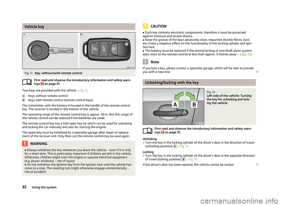
Vehicle keyFig. 11
Key: without/with remote control
First read and observe the introductory information and safety warn- ings
on page 31.
Two keys are provided with the vehicle » Fig. 11.
Keys without remote control
Keys with remote control (remote control keys)
The transmitter with the battery is housed in the handle of the remote control key. The receiver is located in the interior of the vehicle.
The operating range of the remote control key is approx. 30 m. But this range ofthe remote control can be reduced if the batteries are weak.
The remote control key has a fold-open key bit which can be used for unlocking
and locking the car manually and also for starting the engine.
The spare key must by initialised by a specialist garage after repair or replace-
ment of the receiver unit. Only then can the remote control key be used again.
WARNING■ Always withdraw the key whenever you leave the vehicle – even if it is only
for a short time. This is particularly important if children are left in the vehicle.
Otherwise, children might start the engine or operate electrical equipment
(e.g. power windows) – risk of injury!■
Do not withdraw the ignition key from the ignition lock until the vehicle has
come to a stop. The steering lock might otherwise engage unintentionally –
risk of accident!
CAUTION■ Each key contains electronic components; therefore it must be protected
against moisture and severe shocks.■
Keep the groove of the keys absolutely clean. Impurities (textile fibres, dust,
etc.) have a negative effect on the functionality of the locking cylinder and igni-
tion lock.
■
The battery must be replaced if the central locking or anti-theft alarm system
does react to the remote control at less than approx. 3 metres away » page 193.
Note
If you lose a key, please contact a specialist garage, which will be able to provide
you with a new one.
Unlocking/locking with the key
Fig. 12
Left side of the vehicle: Turning
the key for unlocking and lock-
ing the vehicle
First read and observe the introductory information and safety warn-
ings on page 31.
Unlocking
›
Turn the key in the locking cylinder of the driver's door in the direction of travel
(unlocking position)
A
» Fig. 12 .
Locking
›
Turn the key in the locking cylinder of the driver's door in the opposite direction
of travel (locking position)
B
» Fig. 12 .
If the driver's door has been opened, the vehicle cannot be locked.
32Using the system
Page 37 of 226
Switch-off display
The indicator light in the driver door flashes for about 2 seconds fast, goes out
and starts to flash at longer intervals after about 30 seconds.WARNINGIf the car is locked and the safe securing system activated, no people must re- main in the car as it will then not be possible to either unlock a door or open a
window from the inside. The locked doors make it more difficult for rescuers
to get into the vehicle in an emergency – risk to life!
Note
This function only applies to certain countries.
Individual settings
First read and observe the introductory information and safety warn-
ings
on page 31.
Opening a single door
This function makes it possible to only unlock the driver's door. The other doors
remain locked and are only unlocked when the command is repeated.
Automatic locking/unlocking
All doors are locked from a speed of around 15 km/h. The button in the handle of
the boot lid is deactivated.
If the ignition key is withdrawn, the car is then automatically unlocked again. In addition, it is possible for the driver or front passenger to unlock the car by press- ing the central locking button
.
The vehicle doors can be unlocked and opened at any time by pulling once on the door opening lever.
Note
Individual settings can be carried out in a specialist workshop.
Locking/unlocking the vehicle from the insideFig. 14
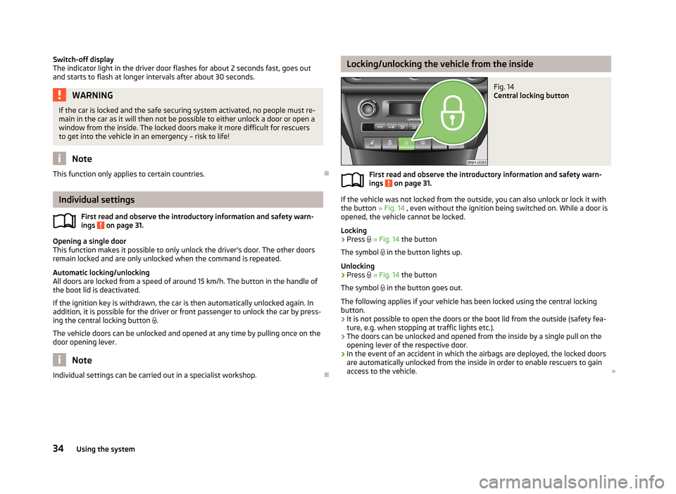
Central locking button
First read and observe the introductory information and safety warn-ings on page 31.
If the vehicle was not locked from the outside, you can also unlock or lock it with
the button » Fig. 14 , even without the ignition being switched on. While a door is
opened, the vehicle cannot be locked.
Locking
›
Press
» Fig. 14 the button
The symbol
in the button lights up.
Unlocking
›
Press
» Fig. 14 the button
The symbol
in the button goes out.
The following applies if your vehicle has been locked using the central locking button.
› It is not possible to open the doors or the boot lid from the outside (safety fea-
ture, e.g. when stopping at traffic lights etc.).
› The doors can be unlocked and opened from the inside by a single pull on the
opening lever of the respective door.
› In the event of an accident in which the airbags are deployed, the locked doors
are automatically unlocked from the inside in order to enable rescuers to gain access to the vehicle.
34Using the system
Page 40 of 226
Switching off›Switch off the ignition.›
Open the driver door.
›
Press the symbol button » Fig. 17 on the B-column on the driver's side. The
symbol lighting in the button changes from red to orange.
›
Lock the vehicle within 30 seconds.
The interior monitor and the towing protection are activated automatically after
the vehicle is locked.
Deactivate the interior monitor and the towing protection if there is a possibility
of the alarm being triggered by movement (e.g. children or animals) from within
the vehicle interior or if the vehicle has to be transported (e.g. by train or ship) or
towed.
CAUTION
■ The opened glasses storage compartment reduces the effectiveness of the in-
terior monitor. To ensure the full functionality of the interior monitor, the glasses storage compartment must always be closed before locking the vehicle.■
The anti-theft alarm system is activated when the vehicle is locked, even if the
safe securing system is deactivated. The interior monitor is however not activa-
ted.
Luggage compartment lid
Introduction
This chapter contains information on the following subjects:
Opening/closing
38
Automatic locking
38WARNING■ Ensure that the lock is properly engaged after closing the boot lid. Other-
wise, the boot lid might open suddenly while the vehicle is moving, even if it was locked – risk of accident!■
Never drive with the boot lid open or unlatched, as otherwise exhaust gases
may get into the interior of the vehicle – risk of poisoning!
■
Do not press on the rear window when closing the luggage compartment lid,
as otherwise it could crack – risk of injury!
CAUTION■ If the vehicle was locked before the boot lid was closed, the lid is immediately
locked automatically when closed.■
Do not press on the rear window when closing the tailgate, it could crack.
Note
The function of the button in the grip above the licence plate is deactivated when
starting off or at a speed of 5 km/hour or more for vehicles with central locking.
The function is restored after the vehicle stops and the door is opened.
37Unlocking and opening
Page 45 of 226
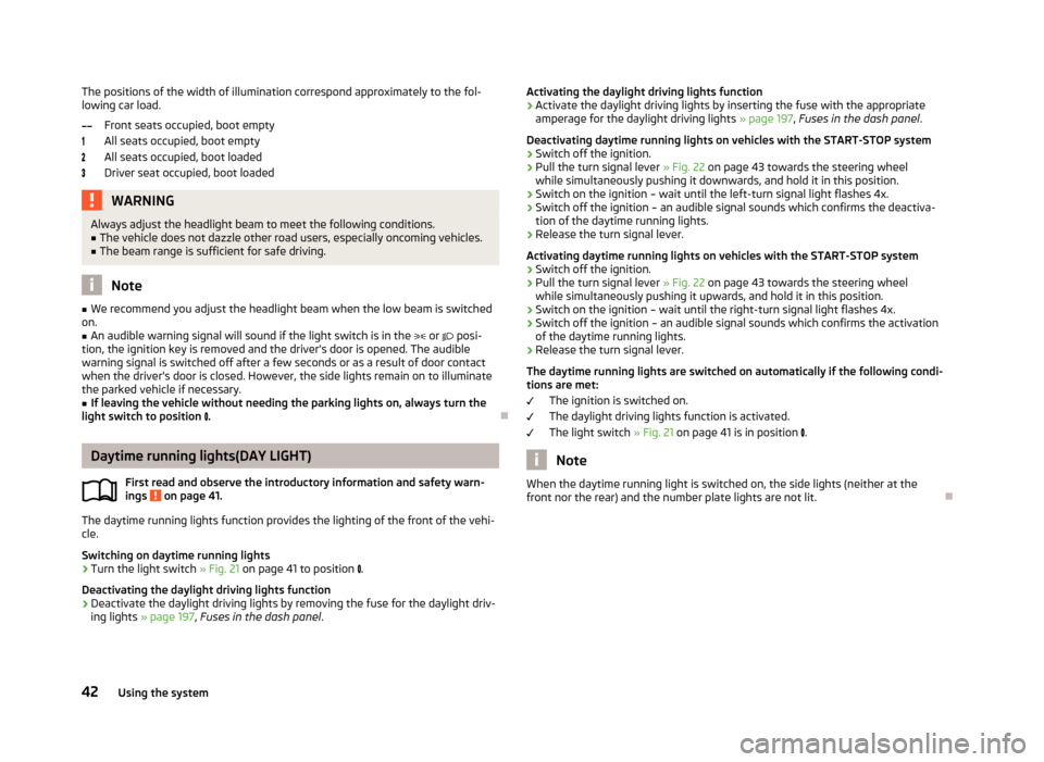
The positions of the width of illumination correspond approximately to the fol-
lowing car load.
Front seats occupied, boot empty
All seats occupied, boot empty
All seats occupied, boot loaded
Driver seat occupied, boot loadedWARNINGAlways adjust the headlight beam to meet the following conditions.■The vehicle does not dazzle other road users, especially oncoming vehicles.■
The beam range is sufficient for safe driving.
Note
■ We recommend you adjust the headlight beam when the low beam is switched
on.■
An audible warning signal will sound if the light switch is in the or posi-
tion, the ignition key is removed and the driver's door is opened. The audible warning signal is switched off after a few seconds or as a result of door contact
when the driver's door is closed. However, the side lights remain on to illuminate the parked vehicle if necessary.
■
If leaving the vehicle without needing the parking lights on, always turn the
light switch to position .
Daytime running lights(DAY LIGHT)
First read and observe the introductory information and safety warn-
ings
on page 41.
The daytime running lights function provides the lighting of the front of the vehi-
cle.
Switching on daytime running lights
›
Turn the light switch » Fig. 21 on page 41 to position
.
Deactivating the daylight driving lights function
›
Deactivate the daylight driving lights by removing the fuse for the daylight driv-
ing lights » page 197 , Fuses in the dash panel .
Activating the daylight driving lights function›Activate the daylight driving lights by inserting the fuse with the appropriate
amperage for the daylight driving lights » page 197, Fuses in the dash panel .
Deactivating daytime running lights on vehicles with the START-STOP system›
Switch off the ignition.
›
Pull the turn signal lever » Fig. 22 on page 43 towards the steering wheel
while simultaneously pushing it downwards, and hold it in this position.
›
Switch on the ignition – wait until the left-turn signal light flashes 4x.
›
Switch off the ignition – an audible signal sounds which confirms the deactiva- tion of the daytime running lights.
›
Release the turn signal lever.
Activating daytime running lights on vehicles with the START-STOP system
›
Switch off the ignition.
›
Pull the turn signal lever » Fig. 22 on page 43 towards the steering wheel
while simultaneously pushing it upwards, and hold it in this position.
›
Switch on the ignition – wait until the right-turn signal light flashes 4x.
›
Switch off the ignition – an audible signal sounds which confirms the activation
of the daytime running lights.
›
Release the turn signal lever.
The daytime running lights are switched on automatically if the following condi- tions are met:
The ignition is switched on.
The daylight driving lights function is activated.
The light switch » Fig. 21 on page 41 is in position
.
Note
When the daytime running light is switched on, the side lights (neither at the
front nor the rear) and the number plate lights are not lit.42Using the system
Page 84 of 226
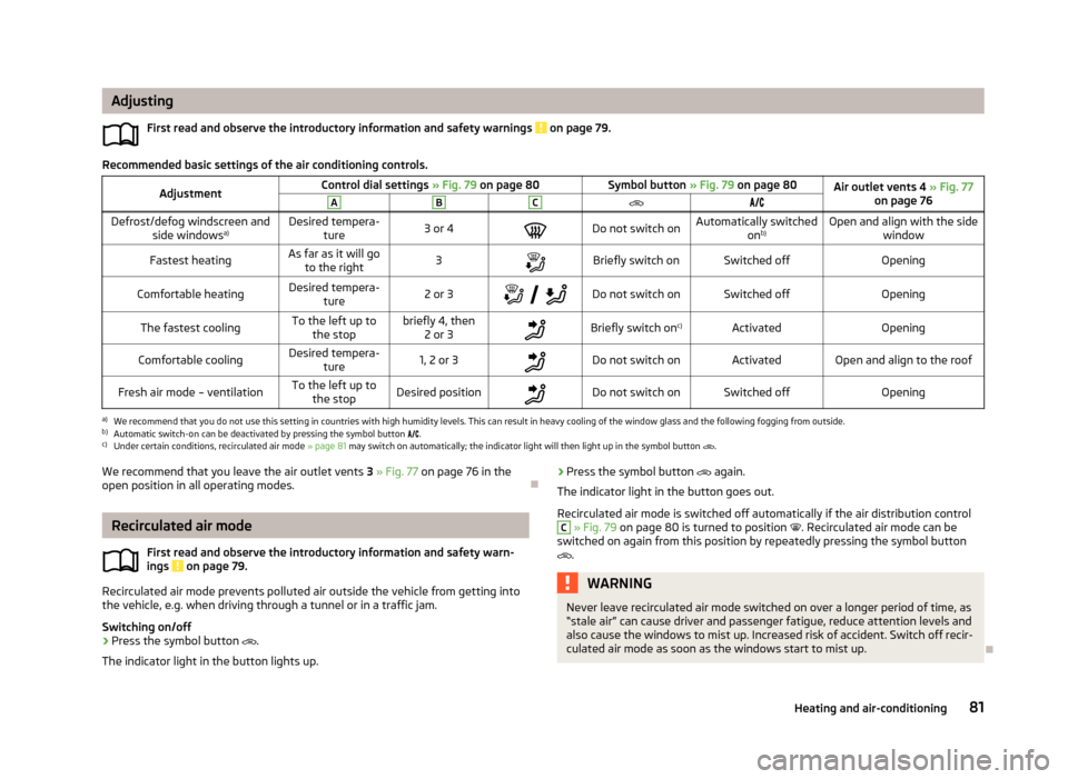
AdjustingFirst read and observe the introductory information and safety warnings
on page 79.
Recommended basic settings of the air conditioning controls.
AdjustmentControl dial settings » Fig. 79 on page 80Symbol button » Fig. 79 on page 80Air outlet vents 4 » Fig. 77
on page 76ABCDefrost/defog windscreen and side windows a)Desired tempera-
ture3 or 4Do not switch onAutomatically switched onb)Open and align with the side
windowFastest heatingAs far as it will goto the right3Briefly switch onSwitched offOpeningComfortable heatingDesired tempera-
ture2 or 3
Do not switch onSwitched offOpeningThe fastest coolingTo the left up to
the stopbriefly 4, then 2 or 3Briefly switch on c)ActivatedOpeningComfortable coolingDesired tempera-
ture1, 2 or 3Do not switch onActivatedOpen and align to the roofFresh air mode – ventilationTo the left up tothe stopDesired positionDo not switch onSwitched offOpeninga)
We recommend that you do not use this setting in countries with high humidity levels. This can result in heavy cooling of the window glass and the following fogging from outside.
b)
Automatic switch-on can be deactivated by pressing the symbol button .
c)
Under certain conditions, recirculated air mode
» page 81 may switch on automatically; the indicator light will then light up in the symbol button
.
We recommend that you leave the air outlet vents
3 » Fig. 77 on page 76 in the
open position in all operating modes.
Recirculated air mode
First read and observe the introductory information and safety warn-ings
on page 79.
Recirculated air mode prevents polluted air outside the vehicle from getting into
the vehicle, e.g. when driving through a tunnel or in a traffic jam.
Switching on/off
›
Press the symbol button
.
The indicator light in the button lights up.
› Press the symbol button
again.
The indicator light in the button goes out.
Recirculated air mode is switched off automatically if the air distribution controlC
» Fig. 79 on page 80 is turned to position . Recirculated air mode can be
switched on again from this position by repeatedly pressing the symbol button
.
WARNINGNever leave recirculated air mode switched on over a longer period of time, as
“stale air” can cause driver and passenger fatigue, reduce attention levels and also cause the windows to mist up. Increased risk of accident. Switch off recir-
culated air mode as soon as the windows start to mist up.
81Heating and air-conditioning
Page 97 of 226
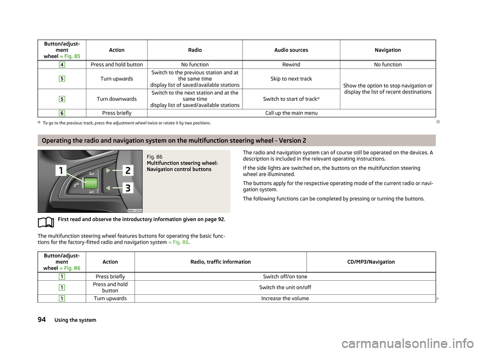
Button/adjust-ment
wheel » Fig. 85ActionRadioAudio sourcesNavigation
4Press and hold buttonNo functionRewindNo function5
Turn upwardsSwitch to the previous station and at
the same time
display list of saved/available stationsSkip to next trackShow the option to stop navigation or display the list of recent destinations
5
Turn downwardsSwitch to the next station and at the same time
display list of saved/available stationsSwitch to start of track a)
6Press brieflyCall up the main menua)
To go to the previous track, press the adjustment wheel twice or rotate it by two positions.
Operating the radio and navigation system on the multifunction steering wheel - Version 2
Fig. 86
Multifunction steering wheel:
Navigation control buttons
First read and observe the introductory information given on page 92.
The multifunction steering wheel features buttons for operating the basic func-
tions for the factory-fitted radio and navigation system » Fig. 86.
The radio and navigation system can of course still be operated on the devices. A
description is included in the relevant operating instructions.
If the side lights are switched on, the buttons on the multifunction steeringwheel are illuminated.
The buttons apply for the respective operating mode of the current radio or navi-
gation system.
The following functions can be completed by pressing or turning the buttons.Button/adjust- ment
wheel » Fig. 86ActionRadio, traffic informationCD/MP3/Navigation
1Press brieflySwitch off/on tone1Press and hold
buttonSwitch the unit on/off1Turn upwardsIncrease the volume 94Using the system