air condition SKODA RAPID 2014 1.G User Guide
[x] Cancel search | Manufacturer: SKODA, Model Year: 2014, Model line: RAPID, Model: SKODA RAPID 2014 1.GPages: 200, PDF Size: 25.57 MB
Page 65 of 200
COMING HOME / LEAVING HOMERead and observe
on page 58 first.
COMING HOME (hereinafter referred to only as a function) switches the light
automatically for a short time after leaving the vehicle.
LEAVING HOME (hereinafter referred to only as a function) switches the light
automatically for a short time when approaching the vehicle.
The function switches on the following light, depending on the equipment
fitted.
› Parking lights,
› Low beam
› Entry lighting in the exterior mirrors
› Licence plate light
Poorer visibility is evaluated by sensor mounted in the holder of the interior
mirror.
COMING HOME
The lights are switched on automatically if the following conditions are met.
The light switch is in position
» Fig. 41 on page 60 .
The visibility in the vehicle environment is reduced.
The ignition is switched off.
The function was activated before leaving the vehicle by briefly switching
on the headlight flasher » page 60, Turn signal and main beam .
The driver's door was open - within 60 seconds after turning off the igni-
tion.
The light goes out 10 seconds after closing all of the doors and the boot lid.
If a door or the boot lid remains open, the light goes out after 60 seconds.
LEAVING HOME
The lights are switched on automatically if the following conditions are met.
The light switch is in position
» Fig. 41 on page 60 .
The visibility in the vehicle environment is reduced.
The ignition is switched off.
The vehicle was unlocked with the radio remote control.
The light goes off after 10 seconds or when locking the vehicle.
CAUTION■
Do not attach any stickers or similar objects in front of the light sensor on
the windscreen to avoid impairing the function or its reliability.■
If this function is activated constantly, the battery will be heavily discharged
particularly in short-haul travel.
Hazard warning light system
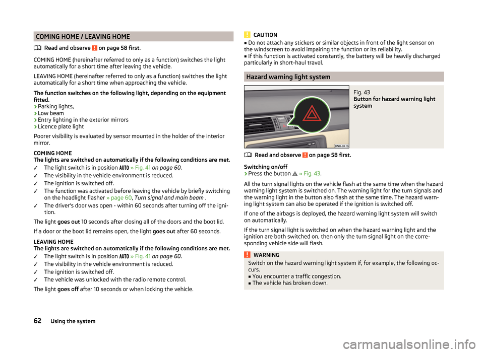
Fig. 43
Button for hazard warning light
system
Read and observe on page 58 first.
Switching on/off
›
Press the button
» Fig. 43 .
All the turn signal lights on the vehicle flash at the same time when the hazard
warning light system is switched on. The warning light for the turn signals and
the warning light in the button also flash at the same time. The hazard warn-
ing light system can also be operated if the ignition is switched off.
If one of the airbags is deployed, the hazard warning light system will switch
on automatically.
If the turn signal light is switched on when the hazard warning light and the
ignition are both switched on, then only the turn signal light on the corre-
sponding vehicle side will flash.
WARNINGSwitch on the hazard warning light system if, for example, the following oc-
curs.■
You encounter a traffic congestion.
■
The vehicle has broken down.
62Using the system
Page 68 of 200
Front sun visorsFig. 47
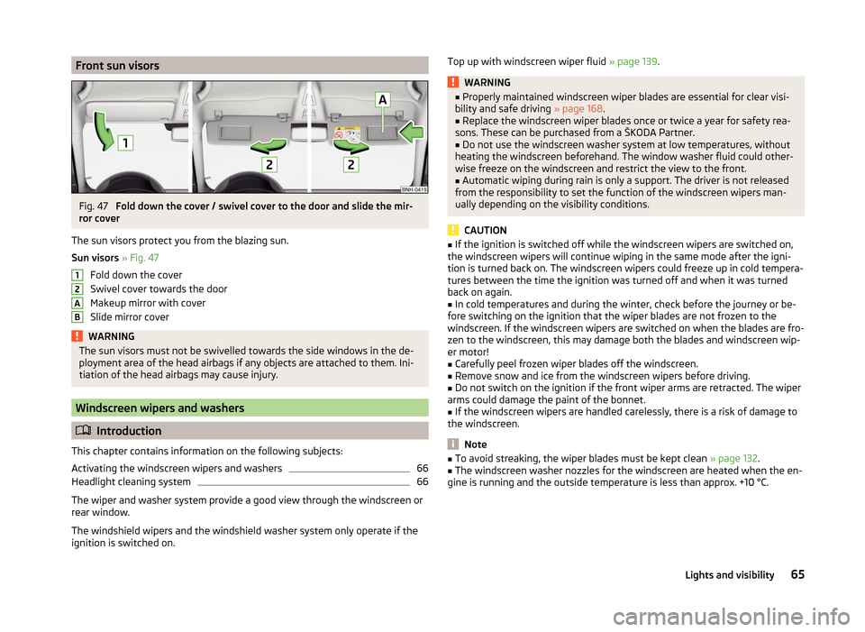
Fold down the cover / swivel cover to the door and slide the mir-
ror cover
The sun visors protect you from the blazing sun.
Sun visors » Fig. 47
Fold down the cover
Swivel cover towards the door
Makeup mirror with cover
Slide mirror cover
WARNINGThe sun visors must not be swivelled towards the side windows in the de-
ployment area of the head airbags if any objects are attached to them. Ini-
tiation of the head airbags may cause injury.
Windscreen wipers and washers
Introduction
This chapter contains information on the following subjects:
Activating the windscreen wipers and washers
66
Headlight cleaning system
66
The wiper and washer system provide a good view through the windscreen or
rear window.
The windshield wipers and the windshield washer system only operate if the
ignition is switched on.
12ABTop up with windscreen wiper fluid » page 139.WARNING■
Properly maintained windscreen wiper blades are essential for clear visi-
bility and safe driving » page 168.■
Replace the windscreen wiper blades once or twice a year for safety rea-
sons. These can be purchased from a ŠKODA Partner.
■
Do not use the windscreen washer system at low temperatures, without
heating the windscreen beforehand. The window washer fluid could other-
wise freeze on the windscreen and restrict the view to the front.
■
Automatic wiping during rain is only a support. The driver is not released
from the responsibility to set the function of the windscreen wipers man-
ually depending on the visibility conditions.
CAUTION
■ If the ignition is switched off while the windscreen wipers are switched on,
the windscreen wipers will continue wiping in the same mode after the igni-
tion is turned back on. The windscreen wipers could freeze up in cold tempera-
tures between the time the ignition was turned off and when it was turned
back on again.■
In cold temperatures and during the winter, check before the journey or be-
fore switching on the ignition that the wiper blades are not frozen to the
windscreen. If the windscreen wipers are switched on when the blades are fro-
zen to the windscreen, this may damage both the blades and windscreen wip-
er motor!
■
Carefully peel frozen wiper blades off the windscreen.
■
Remove snow and ice from the windscreen wipers before driving.
■
Do not switch on the ignition if the front wiper arms are retracted. The wiper
arms could damage the paint of the bonnet.
■
If the windscreen wipers are handled carelessly, there is a risk of damage to
the windscreen.
Note
■ To avoid streaking, the wiper blades must be kept clean » page 132.■The windscreen washer nozzles for the windscreen are heated when the en-
gine is running and the outside temperature is less than approx. +10 °C.65Lights and visibility
Page 82 of 200
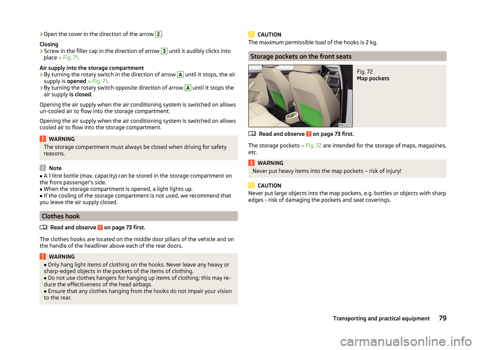
›Open the cover in the direction of the arrow 2.
Closing›
Screw in the filler cap in the direction of arrow
3
until it audibly clicks into
place » Fig. 71 .
Air supply into the storage compartment
›
By turning the rotary switch in the direction of arrow
A
until it stops, the air
supply is opened » Fig. 71 .
›
By turning the rotary switch opposite direction of arrow
A
until it stops the
air supply is closed.
Opening the air supply when the air conditioning system is switched on allows un-cooled air to flow into the storage compartment.
Opening the air supply when the air conditioning system is switched on allows cooled air to flow into the storage compartment.
WARNINGThe storage compartment must always be closed when driving for safety
reasons.
Note
■ A 1 litre bottle (max. capacity) can be stored in the storage compartment on
the front passenger's side.■
When the storage compartment is opened, a light lights up.
■
If the cooling of the storage compartment is not used, we recommend that
you leave the air supply closed.
Clothes hook
Read and observe
on page 73 first.
The clothes hooks are located on the middle door pillars of the vehicle and on
the handle of the headliner above each of the rear doors.
WARNING■ Only hang light items of clothing on the hooks. Never leave any heavy or
sharp-edged objects in the pockets of the items of clothing.■
Do not use clothes hangers for hanging up items of clothing; this may re-
duce the effectiveness of the head airbags.
■
Ensure that any clothes hanging from the hooks do not impair your vision
to the rear.
CAUTIONThe maximum permissible load of the hooks is 2 kg.
Storage pockets on the front seats
Fig. 72
Map pockets
Read and observe on page 73 first.
The storage pockets » Fig. 72 are intended for the storage of maps, magazines,
etc.
WARNINGNever put heavy items into the map pockets – risk of injury!
CAUTION
Never put large objects into the map pockets, e.g. bottles or objects with sharp
edges - risk of damaging the pockets and seat coverings.79Transporting and practical equipment
Page 88 of 200
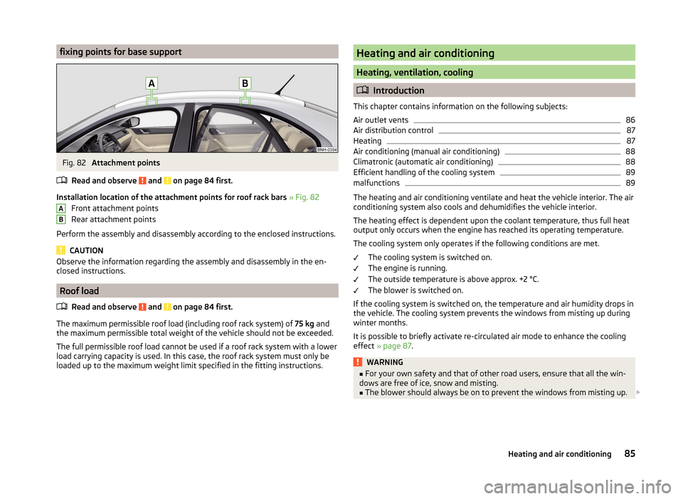
fixing points for base supportFig. 82
Attachment points
Read and observe
and on page 84 first.
Installation location of the attachment points for roof rack bars » Fig. 82
Front attachment points
Rear attachment points
Perform the assembly and disassembly according to the enclosed instructions.
CAUTION
Observe the information regarding the assembly and disassembly in the en-
closed instructions.
Roof load
Read and observe
and on page 84 first.
The maximum permissible roof load (including roof rack system) of 75 kg and
the maximum permissible total weight of the vehicle should not be exceeded.
The full permissible roof load cannot be used if a roof rack system with a lower
load carrying capacity is used. In this case, the roof rack system must only be
loaded up to the maximum weight limit specified in the fitting instructions.
ABHeating and air conditioning
Heating, ventilation, cooling
Introduction
This chapter contains information on the following subjects:
Air outlet vents
86
Air distribution control
87
Heating
87
Air conditioning (manual air conditioning)
88
Climatronic (automatic air conditioning)
88
Efficient handling of the cooling system
89
malfunctions
89
The heating and air conditioning ventilate and heat the vehicle interior. The air
conditioning system also cools and dehumidifies the vehicle interior.
The heating effect is dependent upon the coolant temperature, thus full heat
output only occurs when the engine has reached its operating temperature.
The cooling system only operates if the following conditions are met. The cooling system is switched on.
The engine is running.
The outside temperature is above approx. +2 °C.
The blower is switched on.
If the cooling system is switched on, the temperature and air humidity drops in
the vehicle. The cooling system prevents the windows from misting up during
winter months.
It is possible to briefly activate re-circulated air mode to enhance the cooling
effect » page 87 .
WARNING■
For your own safety and that of other road users, ensure that all the win-
dows are free of ice, snow and misting.■
The blower should always be on to prevent the windows from misting up.
85Heating and air conditioning
Page 89 of 200
WARNING (Continued)■Under certain circumstances, air at a temperature of about 5 °C can flow
out of the vents when the cooling system is switched on.■
To reduce health risks (e.g. common colds), the following instructions for
the use of the cooling system are to be observed. ■The difference between the indoor temperature and the outdoor air
temperature should not be greater than about 5 ° C.
■ The cooling system is to be turned off about 10 minutes before the end
of the journey.
■ Once a year, a disinfection of the air conditioner or the Climatronic is to
be carried out by a specialist company.
CAUTION
■ The air inlet in front of the windscreen must be free from ice, snow or leaves,
for example, to ensure that the heating and cooling system works properly.■
After switching on the cooling Condensation from the evaporator of the air
conditioning may drip down and form a puddle below the vehicle. This is not a
leak!
■
If the coolant temperature is too high, the cooling system is switched off to
ensure that the engine cools down.
Note
The used air streams out through the vents in the luggage compartment.
Air outlet vents
Fig. 83
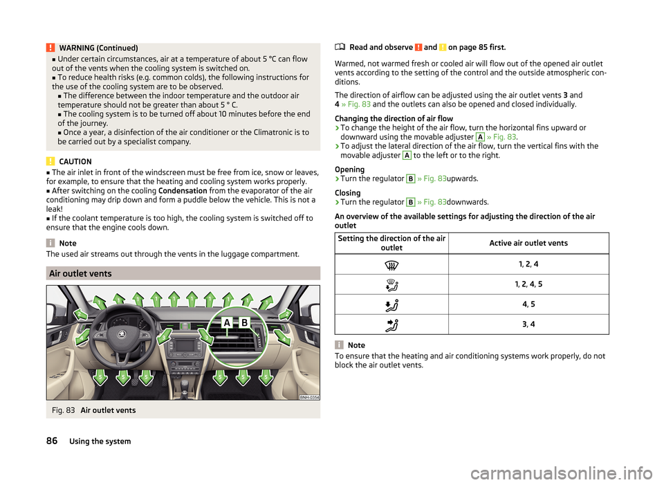
Air outlet vents
Read and observe and on page 85 first.
Warmed, not warmed fresh or cooled air will flow out of the opened air outlet vents according to the setting of the control and the outside atmospheric con-
ditions.
The direction of airflow can be adjusted using the air outlet vents 3 and
4 » Fig. 83 and the outlets can also be opened and closed individually.
Changing the direction of air flow
›
To change the height of the air flow, turn the horizontal fins upward or
downward using the movable adjuster
A
» Fig. 83 .
›
To adjust the lateral direction of the air flow, turn the vertical fins with the
movable adjuster
A
to the left or to the right.
Opening
›
Turn the regulator
B
» Fig. 83 upwards.
Closing
›
Turn the regulator
B
» Fig. 83 downwards.
An overview of the available settings for adjusting the direction of the air
outlet
Setting the direction of the air outletActive air outlet vents1, 2 , 41, 2 , 4 , 54 , 53 , 4
Note
To ensure that the heating and air conditioning systems work properly, do not
block the air outlet vents.86Using the system
Page 90 of 200
Air distribution controlRead and observe
and on page 85 first.
Recirculated air mode mostly prevents polluted air outside the vehicle fromgetting into the vehicle, for example when driving through a tunnel or when
standing in a traffic jam.
In recirculated air mode air is sucked out of the interior of the vehicle and then
fed back into the interior.
Heating and air conditioning (manual air conditioning)
To turn the recirculation mode on or off, press the Symbol key
.
The air recirculation mode is automatically turned off by turning the air distri-
bution control
C
to position
» Fig. 84 on page 87 or » Fig. 85 on
page 88 .
Recirculated air mode can be switched on again from this setting by repeatedly
pressing the symbol button .
Climatronic (automatic air conditioning)
To switch on press the Symbol key
. The symbol
(pos.
7
» Fig. 86 on
page 88 ) appears in the display.
To switch off press the symbol key
again. The
symbol in the display
goes out.
WARNINGThe recirculation system cannot be switched on for a longer period of time,
because there is no supply of fresh air from the outside. “Stale air” may re-
sult in fatigue in the driver and occupants, reduce attention levels and also
cause the windows to mist up. The risk of having an accident increases.
Switch off recirculated air mode as soon as the windows start to mist up.
CAUTION
We recommend not smoking in the vehicle when the recirculating air operation
is switched on. The smoke sucked from inside the vehicle is deposited on the
evaporator of the air conditioner. This produces a permanent odour when the
air conditioning system is operating which can only be eliminated through con-
siderable effort and expense (replacement of compressor).NoteIf recirculated air mode is switched on for around 15 minutes, the symbol
will begin to flash in the Climatronic display as a sign that the recirculated air
mode is switched on long-term. If the recirculated air mode is not switched off,
the symbol flashes for around 5 minutes.
Heating
Fig. 84
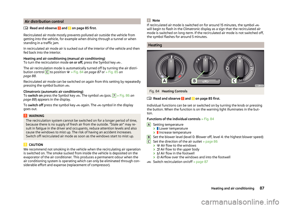
Heating Controls
Read and observe
and on page 85 first.
Individual functions can be set or switched on by turning the knob or pressing the button. When the function is on the warning light illuminates in the but-
ton.
Functions of the individual controls » Fig. 84
Setting temperature ›
Lower temperature
›
Increase temperature
Set the blower level (level 0: Blower off, level 4: the highest blower speed)
Set the direction of the air outlet » page 86
›
Air flow to the windows
›
Air flow to the upper body
›
Air flow in the footwell
›
Airflow over the windows and into the footwell
Switch recirculation on/off » page 87
ABC87Heating and air conditioning
Page 91 of 200
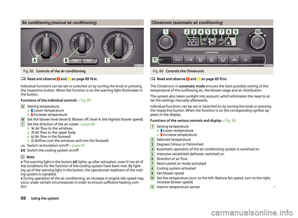
Air conditioning (manual air conditioning)Fig. 85
Controls of the air conditioning
Read and observe
and on page 85 first.
Individual functions can be set or switched on by turning the knob or pressing the respective button. When the function is on the warning light illuminates in
the button.
Functions of the individual controls » Fig. 85
Setting temperature ›
Lower temperature
›
Increase temperature
Set the blower level (level 0: Blower off, level 4: the highest blower speed)
Set the direction of the air outlet » page 86
›
Air flow to the windows
›
Air flow to the upper body
›
Air flow in the footwell
›
Airflow over the windows and into the footwell
Switch recirculation on/off » page 87
Switch the cooling system on/off
Note
■ The warning light in the button lights up after activation, even if not all of
the conditions for the function of the cooling system have been met. By light-
ing up of the warning light in the button, the operational readiness of the cool-
ing system is signalled.■
During operation of the air conditioning, an increase in engine idle speed may
occur under certain circumstances in order to ensure sufficient heating com-
fort.
ABCClimatronic (automatic air conditioning)Fig. 86
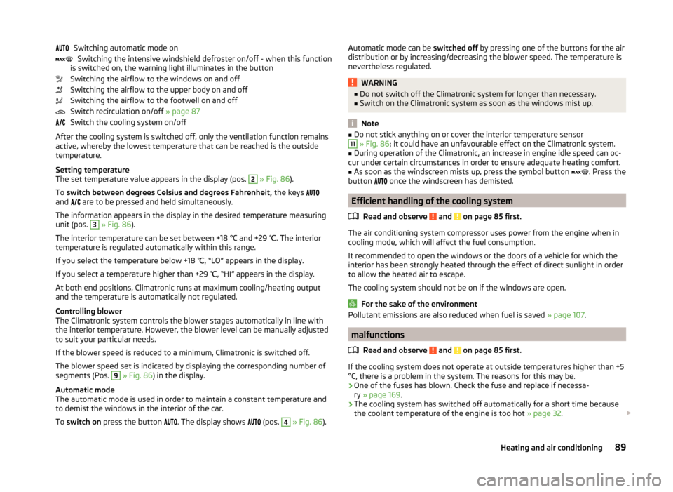
Controls the Climatronic
Read and observe
and on page 85 first.
The Climatronic in automatic mode ensures the best-possible setting of the
temperature of the outflowing air, the blower stage and air distribution.
The system also takes sunlight into account, which eliminates the need to al-
ter the settings manually afterwards.
Individual functions can be set or switched on by turning the knob or pressing
the respective button. When the function is on the corresponding symbol ap-
pears in the display.
Functions of the various controls and display » Fig. 86
Setting temperature ›
Lower temperature
›
Increase temperature
Selected temperature
Degrees Celsius or Fahrenheit
Automatic operation of the air conditioning system is switched on
Intensive windshield defroster switched on
Direction of air flow
Recirculated air mode activated
Cooling system activated
Set blower speed
Set the temperature (turn to the left: Reduce fan speed, turn to the right:
Increase blower speed)
Interior temperature sensor
123456789101188Using the system
Page 92 of 200
Switching automatic mode onSwitching the intensive windshield defroster on/off - when this function
is switched on, the warning light illuminates in the button
Switching the airflow to the windows on and off
Switching the airflow to the upper body on and off
Switching the airflow to the footwell on and off
Switch recirculation on/off » page 87
Switch the cooling system on/off
After the cooling system is switched off, only the ventilation function remains active, whereby the lowest temperature that can be reached is the outside
temperature.
Setting temperature
The set temperature value appears in the display (pos. 2
» Fig. 86 ).
To switch between degrees Celsius and degrees Fahrenheit, the keys
and are to be pressed and held simultaneously.
The information appears in the display in the desired temperature measuring
unit (pos.
3
» Fig. 86 ).
The interior temperature can be set between +18 °C and +29 ℃. The interior
temperature is regulated automatically within this range.
If you select the temperature below +18 ℃, “LO” appears in the display.
If you select a temperature higher than +29 ℃, “HI” appears in the display.
At both end positions, Climatronic runs at maximum cooling/heating output
and the temperature is automatically not regulated.
Controlling blower
The Climatronic system controls the blower stages automatically in line with the interior temperature. However, the blower level can be manually adjusted
to suit your particular needs.
If the blower speed is reduced to a minimum, Climatronic is switched off.
The blower speed set is indicated by displaying the corresponding number of
segments (Pos.
9
» Fig. 86 ) in the display.
Automatic mode
The automatic mode is used in order to maintain a constant temperature and to demist the windows in the interior of the car.
To switch on press the button
. The display shows
(pos.
4
» Fig. 86 ).
Automatic mode can be
switched off by pressing one of the buttons for the air
distribution or by increasing/decreasing the blower speed. The temperature is
nevertheless regulated.WARNING■ Do not switch off the Climatronic system for longer than necessary.■Switch on the Climatronic system as soon as the windows mist up.
Note
■Do not stick anything on or cover the interior temperature sensor11 » Fig. 86 ; it could have an unfavourable effect on the Climatronic system.■
During operation of the Climatronic, an increase in engine idle speed can oc-
cur under certain circumstances in order to ensure adequate heating comfort.
■
As soon as the windscreen mists up, press the symbol button
. Press the
button
once the windscreen has demisted.
Efficient handling of the cooling system
Read and observe
and on page 85 first.
The air conditioning system compressor uses power from the engine when incooling mode, which will affect the fuel consumption.
It recommended to open the windows or the doors of a vehicle for which the
interior has been strongly heated through the effect of direct sunlight in order
to allow the heated air to escape.
The cooling system should not be on if the windows are open.
For the sake of the environment
Pollutant emissions are also reduced when fuel is saved » page 107.
malfunctions
Read and observe
and on page 85 first.
If the cooling system does not operate at outside temperatures higher than +5°C, there is a problem in the system. The reasons for this may be.
› One of the fuses has blown. Check the fuse and replace if necessa-
ry » page 169 .
› The cooling system has switched off automatically for a short time because
the coolant temperature of the engine is too hot » page 32.
89Heating and air conditioning
Page 101 of 200
AUX input
For vehicles with an AUX input this depends on the equipment and is located
at one of the following locations.
› Between the front seats in the centre console
» Fig. 90 -
.
› Above the storage box of the front centre console
» Fig. 90 –
.
› On the front of the Amundsen+ navigation system.
The AUX input is indicated with the lettering
.
Audio devices can be connected via the standard 3.5 mm jack plug to the input.
USB input
If vehicles are equipped with the USB input, this will be located above the stor-
age compartment in the front centre console » Fig. 90 -
.
The USB input is indicated with the symbol .
USB devices can be connected at the input (such as storage sources).
SmartGate
Introduction
This chapter contains information on the following subjects:
Connection with SmartGate
98
Smart Gate website
99
Password Management
99
SmartGate is a system which transmits vehicle data via Wi-Fi.
The ŠKODA applications installed in a connected communications device (e.g.
phone, tablet, notebook) 1)
offer the possibility to further process the received
data.
Available applications and further information can be found on the ŠKODA
website..
WARNING■ The national legal regulations for using mobile communication devices in
a vehicle must be observed.■
Do not fit the equipment or mounts to be connected onto airbag covers
or within the immediate deployment range of the airbags.
■
Never leave a connected device in the deployment area of an airbag, on a
seat, on the dash panel or any another area, from which it can be thrown
during a sudden braking manoeuvre, an accident or a collision - there is a
risk of injury.
Note
The Wi-Fi range is limited to the interior of the vehicle.
Connection with SmartGate
Read and observe
on page 98 first.
For a successful connection the following conditions must be met. Wi-Fi is turned on in the device to be connected.
The ignition is switched on.
Connect
›
Can enable the connected device to search for available Wi-Fi networks (see
operating instructions for the connected device).
›
In the found networks menu, select the connection to the
“SmartGate_ ... ”network 2)
.
›
Enter the password (the password is preset at the factory to the complete
Vehicle Identification Number - enter capital letters).
Disconnecting the connection
The connection to SmartGate can be ended in the following ways.
›
By disconnecting the connected device from SmartGate.
›
By turning off the Wi-Fi in the connected device.
›
By switching off the ignition and removing the key for more than 5 s (for ve-
hicles with starter button - by turning off the engine and opening the driver's
door).
1)
The applications support communication devices with the Android operating system version 4.0.x and
later and iOS 7.xx and higher.
2)
The last six symbols of the VIN vehicle identification number of your vehicle are displayed at position ....
98Using the system
Page 105 of 200
The engine and the ignition are switched off simultaneously.
For vehicles with automatic transmission, the ignition key can only be removed if the selector lever is in position P .
CAUTION
Do not switch the engine off immediately at the end of your journey after the
engine has been operated over a prolonged period at high loads but leave it to
run at an idling speed for about 1 minute. This prevents any possible accumula-
tion of heat when the engine is switched off.
Note
After switching off the ignition, the radiator fan may intermittently continue to
operate for approx. 10 minutes.
Brakes and parking
Introduction
This chapter contains information on the following subjects:
Information on braking
102
Handbrake
103
Parking
103WARNING■ Greater physical effort is required for braking when the engine is switch-
ed off – risk of accident!■
The clutch pedal must be actuated when braking on a vehicle with man-
ual transmission, when the vehicle is in gear and at low revs. Otherwise,
the functionality of the brake system may be impaired – risk of accident!
■
When leaving the vehicle, never leave persons who might, for example,
release the handbrake or take the vehicle out of gear unattended in the ve-
hicle. The vehicle could then start to move – risk of accident!
■
Observe the recommendations on the new brake pads » page 107, New
brake pads .
CAUTION
Never let the brakes slip with light pressure on the pedal if braking is not nec-
essary. This causes the brakes to overheat and can also result in a longer brak-
ing distance and excessive wear.Information on braking
Read and observe
and on page 102 first.
Wear-and-tear
The wear of the brake pads is dependent on the operating conditions and driv-
ing style.
The brake pads wear more quickly if a lot of journeys are completed in towns
and over short distances or if a very sporty style of driving is adopted.
Under these severe conditions , the thickness of the brake pads must also be
checked by a specialist garage between service intervals.
Wet roads or road salt
The performance of the brakes can be delayed as the brake discs and brake
pads may be moist or have a coating of ice or layer of salt on them in winter.
The brakes are cleaned and dried by applying the brakes several times »
.
Corrosion
Corrosion on the brake discs and dirt on the bake pads occur if the vehicle has
been parked for a long period and if you do not make much use of the braking
system. The brakes are cleaned by applying the brakes several times »
.
Long or steep slopes
Before travelling a long distance with a steep gradient, reduce speed and shift
into the next lowest gear. As a result, the braking effect of the engine will be
used, reducing the load on the brakes. Any additional braking should be com-
pleted intermittently, not continuously.
Emergency brake display
If the brakes are applied in full and the control unit for the braking system con-
siders the situation to be dangerous for the following traffic, the brake light
flashes automatically.
After the speed was reduced below around 10 km/h or the vehicle was stop-
ped, the brake light stops flashing and the hazard warning light system
switches on. The hazard warning light system is switched off automatically af- ter accelerating or driving off again.
Faults in the brake surface
If it is found that the braking distance has suddenly become longer and that
the brake pedal can be depressed further, the brake system may be faulty.
Visit a specialist garage immediately and adjust your style of driving appropri-
ately, as you will not know the exact extent of the damage.
102Driving