key SKODA RAPID 2014 1.G Owner's Guide
[x] Cancel search | Manufacturer: SKODA, Model Year: 2014, Model line: RAPID, Model: SKODA RAPID 2014 1.GPages: 200, PDF Size: 25.57 MB
Page 140 of 200
All diesel engines can be operated using diesel fuel with at most 7% biodiesel
(B7) 1)
.
Operation in winter – Winter-grade diesel fuel
In the cold season, only use “winter-grade diesel fuel” which will still operate
properly even at a temperature of -20 °C.
It is often the case in countries with different climatic conditions that diesel
fuels available have a different temperature characteristic. ŠKODA Partners
and filling stations in the relevant country will be able to provide you with in-
formation regarding the diesel fuels available.
Diesel fuel additives
The diesel fuel in accordance with the prescribed standards meets all the con-
ditions for a smooth running engine. We therefore recommend that no diesel
fuel additives are used. This can result in considerable damage to parts of the
engine or the exhaust system.
CAUTION
■ Just filling the tank once with diesel fuel that does not comply with the
standard, can cause severe damage to parts of the engine, the fuel and ex-
haust system!■
If a different fuel other than diesel fuel, which complies to the above men-
tioned standards (e.g. petrol) is used, do not start the engine or switch on the
ignition! Extensive damage to engine parts can occur!
■
Water which has collected in the fuel filter can cause engine faults.
CAUTION
■ The vehicle cannot be operated with bio fuel RME, therefore this fuel must
not be filled in the tank and used for driving the vehicle. The use of biofuel
RME can cause considerable damage to parts of the engine or fuel system.■
Do not mix any fuel additives, so-called “flow improvers” (petrol and similar
agents) into the diesel. This can result in considerable damage to parts of the
engine or the exhaust system.
Engine compartment
Introduction
This chapter contains information on the following subjects:
Opening and closing the bonnet
138
Engine compartment overview
139
Radiator fan
139
Windscreen washer system
139WARNINGInjuries or scolding or risks of accident or fire may occur when working in
the engine compartment. For this reason, it is essential to comply with the
warning instructions outlined below and with the general applicable safety
rules. The engine compartment of your car is a hazardous area!WARNINGInstructions before beginning work in the engine compartment■Turn off the engine and withdraw the ignition key.■
Firmly apply the handbrake.
■
For vehicles with manual transmission the lever into the neutral position.
■
On vehicles with automatic transmission, shift the selector lever into the
P position.
■
Allow the engine to cool.
■
Never open the bonnet if you can see steam or coolant escaping from the
engine compartment – risk of scalding! Wait until no more steam or coolant
is escaping.
WARNINGInformation for working in the engine compartment■Keep all people, especially children, away from the engine compartment.■
Never touch the radiator fan while the engine is still warm. The fan might
suddenly start running!
■
Do not touch any hot engine parts – risk of burns!
1)
In Germany according to the DIN 52638 standard, in Austria ÖNORM C 1590, in France EN 590.
137Inspecting and replenishing
Page 158 of 200
›Remove the fire extinguisher.›For mounting, fit the fire extinguisher back into the holder and secure it with
straps.
Please read carefully the instructions which are attached to the fire extin-
guisher.
The fire extinguisher must be checked by an authorised person once a year.
The national legal requirements must be observed.WARNINGThe fire extinguisher must always be secured safely so that they do not
come loose when making an emergency braking or in a vehicle collision
which could cause injuries to occupants.
Note
■ The fire extinguisher must comply with national legal requirements.■Pay attention to the expiration date of the fire extinguisher. Proper function-
ing of the fire extinguisher is not assured once it has passed its expiry date.■
The fire extinguisher is part of the scope of delivery in certain countries only.
Vehicle tool kit
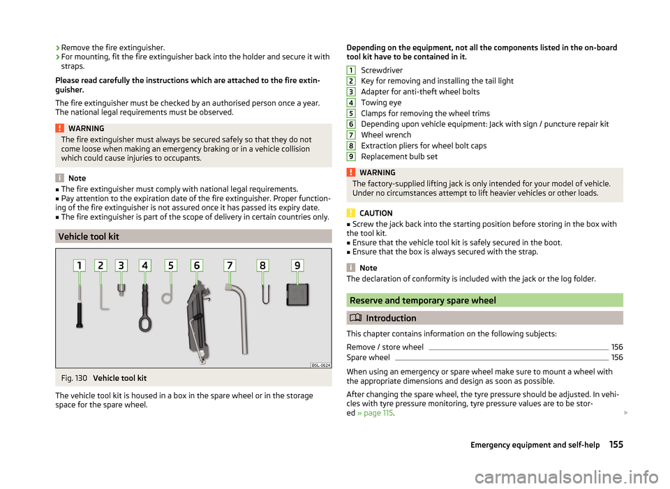
Fig. 130
Vehicle tool kit
The vehicle tool kit is housed in a box in the spare wheel or in the storage
space for the spare wheel.
Depending on the equipment, not all the components listed in the on-board
tool kit have to be contained in it.
Screwdriver
Key for removing and installing the tail light
Adapter for anti-theft wheel bolts
Towing eye
Clamps for removing the wheel trims
Depending upon vehicle equipment: Jack with sign / puncture repair kit
Wheel wrench
Extraction pliers for wheel bolt caps
Replacement bulb setWARNINGThe factory-supplied lifting jack is only intended for your model of vehicle.
Under no circumstances attempt to lift heavier vehicles or other loads.
CAUTION
■ Screw the jack back into the starting position before storing in the box with
the tool kit.■
Ensure that the vehicle tool kit is safely secured in the boot.
■
Ensure that the box is always secured with the strap.
Note
The declaration of conformity is included with the jack or the log folder.
Reserve and temporary spare wheel
Introduction
This chapter contains information on the following subjects:
Remove / store wheel
156
Spare wheel
156
When using an emergency or spare wheel make sure to mount a wheel with
the appropriate dimensions and design as soon as possible.
After changing the spare wheel, the tyre pressure should be adjusted. In vehi- cles with tyre pressure monitoring, tyre pressure values are to be stor-
ed » page 115 .
123456789155Emergency equipment and self-help
Page 169 of 200
CAUTIONThe detachable ball rod and/or the vehicle can be damaged if an unsuitable
tow bar is used.
Remote control
Introduction
This chapter contains information on the following subjects:
Replacing the battery in the remote control key
166
Synchronising the remote control
166
CAUTION
■ The replacement battery must have the same specification as the original
battery.■
We recommend having faulty rechargeable batteries replaced by a ŠKODA
service partner.
■
Pay attention to the correct polarity when changing the battery.
For the sake of the environment
Dispose of the used battery in accordance with national legal provisions.
Replacing the battery in the remote control key
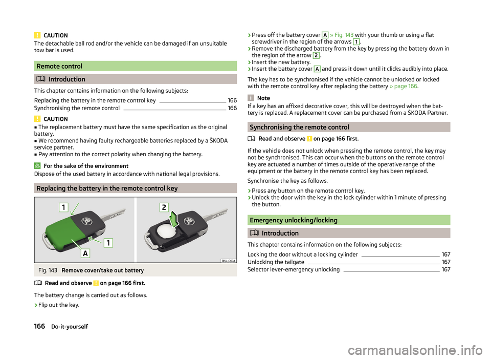
Fig. 143
Remove cover/take out battery
Read and observe
on page 166 first.
The battery change is carried out as follows.
›
Flip out the key.
› Press off the battery cover A
» Fig. 143 with your thumb or using a flat
screwdriver in the region of the arrows 1.›
Remove the discharged battery from the key by pressing the battery down in
the region of the arrow
2
.
›
Insert the new battery.
›
Insert the battery cover
A
and press it down until it clicks audibly into place.
The key has to be synchronised if the vehicle cannot be unlocked or locked
with the remote control key after replacing the battery » page 166.
Note
If a key has an affixed decorative cover, this will be destroyed when the bat-
tery is replaced. A replacement cover can be purchased from a ŠKODA Partner.
Synchronising the remote control
Read and observe
on page 166 first.
If the vehicle does not unlock when pressing the remote control, the key may
not be synchronised. This can occur when the buttons on the remote control
key are actuated a number of times outside of the operative range of the
equipment or the battery in the remote control key has been replaced.
Synchronise the key as follows.
›
Press any button on the remote control key.
›
Unlock the door with the key in the lock cylinder within 1 minute of pressing the button.
Emergency unlocking/locking
Introduction
This chapter contains information on the following subjects:
Locking the door without a locking cylinder
167
Unlocking the tailgate
167
Selector lever-emergency unlocking
167166Do-it-yourself
Page 170 of 200
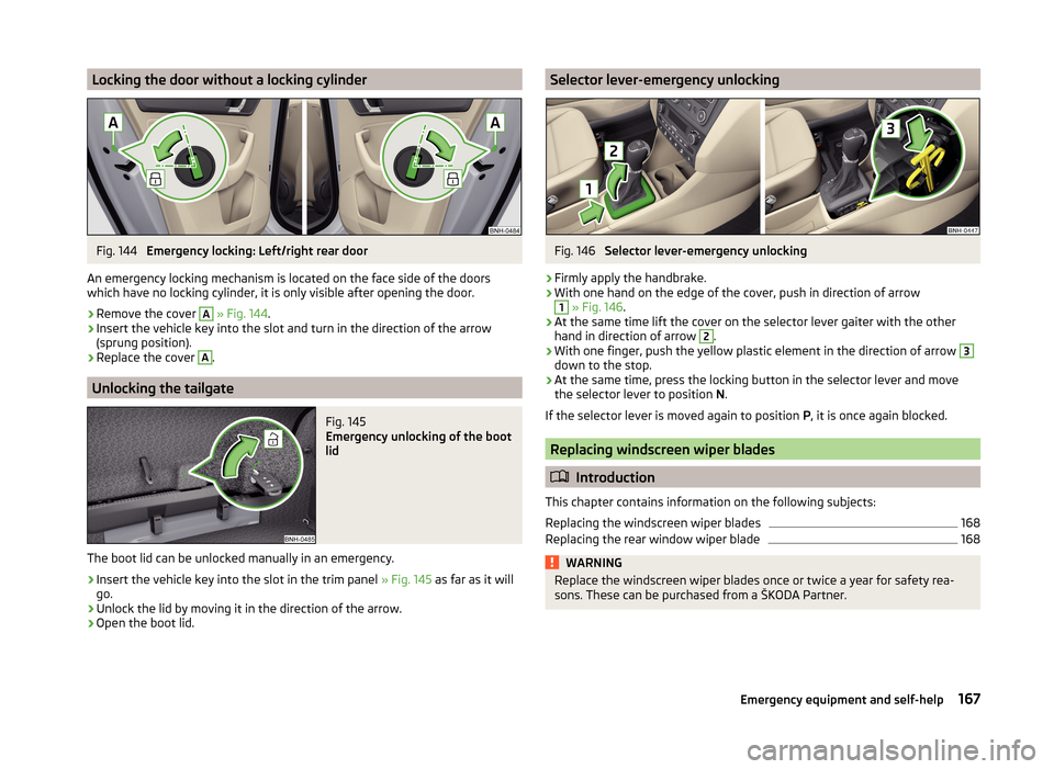
Locking the door without a locking cylinderFig. 144
Emergency locking: Left/right rear door
An emergency locking mechanism is located on the face side of the doors
which have no locking cylinder, it is only visible after opening the door.
›
Remove the cover
A
» Fig. 144 .
›
Insert the vehicle key into the slot and turn in the direction of the arrow
(sprung position).
›
Replace the cover
A
.
Unlocking the tailgate
Fig. 145
Emergency unlocking of the boot
lid
The boot lid can be unlocked manually in an emergency.
›
Insert the vehicle key into the slot in the trim panel » Fig. 145 as far as it will
go.
›
Unlock the lid by moving it in the direction of the arrow.
›
Open the boot lid.
Selector lever-emergency unlockingFig. 146
Selector lever-emergency unlocking
›
Firmly apply the handbrake.
›
With one hand on the edge of the cover, push in direction of arrow
1
» Fig. 146 .
›
At the same time lift the cover on the selector lever gaiter with the other
hand in direction of arrow
2
.
›
With one finger, push the yellow plastic element in the direction of arrow
3
down to the stop.
›
At the same time, press the locking button in the selector lever and movethe selector lever to position N.
If the selector lever is moved again to position P, it is once again blocked.
Replacing windscreen wiper blades
Introduction
This chapter contains information on the following subjects:
Replacing the windscreen wiper blades
168
Replacing the rear window wiper blade
168WARNINGReplace the windscreen wiper blades once or twice a year for safety rea-
sons. These can be purchased from a ŠKODA Partner.167Emergency equipment and self-help
Page 173 of 200
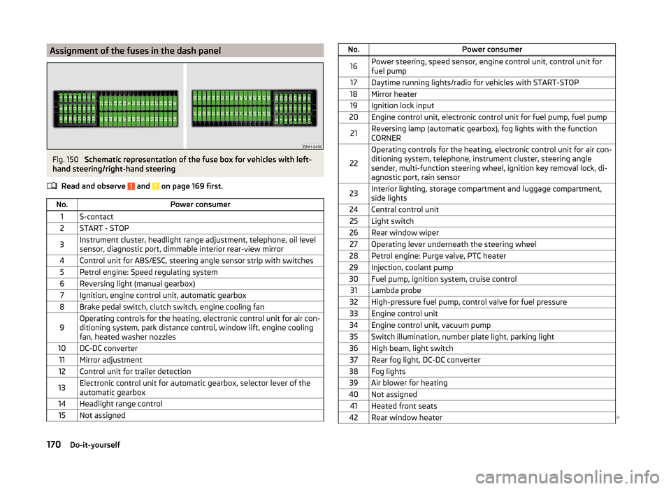
Assignment of the fuses in the dash panelFig. 150
Schematic representation of the fuse box for vehicles with left-
hand steering/right-hand steering
Read and observe
and on page 169 first.
No.Power consumer1S-contact2START - STOP3Instrument cluster, headlight range adjustment, telephone, oil level
sensor, diagnostic port, dimmable interior rear-view mirror4Control unit for ABS/ESC, steering angle sensor strip with switches5Petrol engine: Speed regulating system6Reversing light (manual gearbox)7Ignition, engine control unit, automatic gearbox8Brake pedal switch, clutch switch, engine cooling fan9Operating controls for the heating, electronic control unit for air con-
ditioning system, park distance control, window lift, engine cooling
fan, heated washer nozzles10DC-DC converter11Mirror adjustment12Control unit for trailer detection13Electronic control unit for automatic gearbox, selector lever of the
automatic gearbox14Headlight range control15Not assignedNo.Power consumer16Power steering, speed sensor, engine control unit, control unit for
fuel pump17Daytime running lights/radio for vehicles with START-STOP18Mirror heater19Ignition lock input20Engine control unit, electronic control unit for fuel pump, fuel pump21Reversing lamp (automatic gearbox), fog lights with the function
CORNER
22
Operating controls for the heating, electronic control unit for air con-
ditioning system, telephone, instrument cluster, steering angle
sender, multi-function steering wheel, ignition key removal lock, di-
agnostic port, rain sensor23Interior lighting, storage compartment and luggage compartment,
side lights24Central control unit25Light switch26Rear window wiper27Operating lever underneath the steering wheel28Petrol engine: Purge valve, PTC heater29Injection, coolant pump30Fuel pump, ignition system, cruise control31Lambda probe32High-pressure fuel pump, control valve for fuel pressure33Engine control unit34Engine control unit, vacuum pump35Switch illumination, number plate light, parking light36High beam, light switch37Rear fog light, DC-DC converter38Fog lights39Air blower for heating40Not assigned41Heated front seats42Rear window heater 170Do-it-yourself
Page 177 of 200
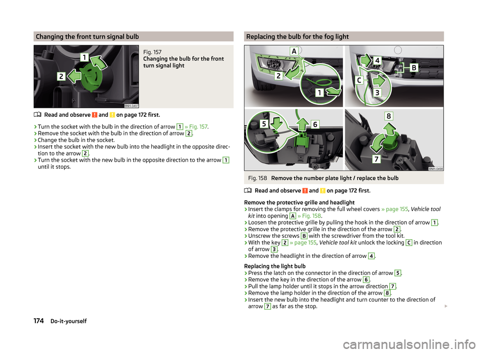
Changing the front turn signal bulbFig. 157
Changing the bulb for the front
turn signal light
Read and observe and on page 172 first.
›
Turn the socket with the bulb in the direction of arrow
1
» Fig. 157 .
›
Remove the socket with the bulb in the direction of arrow
2
.
›
Change the bulb in the socket.
›
Insert the socket with the new bulb into the headlight in the opposite direc-
tion to the arrow
2
.
›
Turn the socket with the new bulb in the opposite direction to the arrow
1
until it stops.
Replacing the bulb for the fog lightFig. 158
Remove the number plate light / replace the bulb
Read and observe
and on page 172 first.
Remove the protective grille and headlight
›
Insert the clamps for removing the full wheel covers » page 155, Vehicle tool
kit into opening
A
» Fig. 158 .
›
Loosen the protective grille by pulling the hook in the direction of arrow
1
.
›
Remove the protective grille in the direction of the arrow
2
.
›
Unscrew the screws
B
with the screwdriver from the tool kit.
›
With the key
2
» page 155 , Vehicle tool kit unlock the locking
C
in direction
of arrow
3
.
›
Remove the headlight in the direction of arrow
4
.
Replacing the light bulb
›
Press the latch on the connector in the direction of arrow
5
.
›
Remove the key in the direction of the arrow
6
.
›
Pull the lamp holder until it stops in the arrow direction
7
.
›
Remove the lamp holder in the direction of the arrow
8
.
›
Insert the new bulb into the headlight and turn counter to the direction of
arrow
7
as far as the stop.
174Do-it-yourself
Page 178 of 200

›Attach the connector.
Refit the headlight and grille›
Replace the fog light by inserting it in the opposite direction of the arrow
4
» Fig. 158 and tightening.
›
Insert the protective grille and carefully press it in.
The protective grille must engage firmly.
Replacing the bulb for the licence plate light
Fig. 159
Remove the number plate light/replace the bulb
Read and observe
and on page 172 first.
›
Open the boot lid.
›
Push in the lamp in the direction of the arrow
1
» Fig. 159 .
The lamp comes loose.
›
Swivel out the lamp in the direction of the arrow
2
and remove it.
›
Remove the faulty bulb from the holder in the direction of the arrow
3
.
›
Insert a new bulb into the holder.
›
Reinsert the lamp in the opposite direction to the arrow
1
.
›
Push on the light until the spring clicks into place.
Check that the light is securely inserted.
Rear LightFig. 160
Remove light / pull out connector
Read and observe
and on page 172 first.
Removing
›
Open the boot lid.
›
Insert the clamps for removing the full wheel covers » page 155, Vehicle tool
kit into opening
A
» Fig. 160 .
›
Remove the cover by pulling the hook in the direction of arrow
1
.
›
Unscrew the screws
B
with the key from the tool kit.
›
Grasp the lamp and carefully remove in the direction of arrow
2
.
›
Press the latch on the connector in the direction of arrow
3
.
›
Carefully remove the connector from the tail lamp assembly in the direction
of the arrow
4
.
Fitting
›
Insert the bulb holder into the lamp.
The lock on the plug must be inserted securely.
›
Insert the lamp with the pin
B
» Fig. 161 on page 176 into the recesses
C
» Fig. 160 in the body.
175Fuses and light bulbs
Page 188 of 200
Index
A
abroad lead-free petrol
135
Abroad Headlights
63
ABS Function
109
Warning light37
Acceptance and recycling of used vehicles127
Accessories124
Adjusting Belt height
15
Exterior mirror68
head restraints70
Interior mirror67
Seat69
Steering wheel10
Adjusting the seats9
Adjustment Beam range
58
Air-conditioning system Air outlet vents
86
Airbag16
Deactivating20
Deactivating the front passenger airbag20
Deployment16
Front airbag17
Head airbag19
Indicator light39
Modifications and damage to the airbag system 126 Side airbag
18
Airbag system16
Air conditioning85
Air distribution control87
Climatronic88
manual air conditioning88
Air distribution control87
Air outlet vents86
Alarm Switching off
53
Triggering53
Alcantara cleaning
133
Anti-theft alarm system Activating/deactivating
54
Trailer122
Anti-theft wheel bolts160
Antilock Braking System109
Armrest Front
72
Rear72
artificial leather133
Ashtray76
ASR warning light
37
Assembling the bar ball, Step 1
118
bar ball, Step 2118
Assist system ABS
109
Assist systems109
ABS37
ASR37
Cruise Control System111
EDL110
ESC37, 109
HBA110
HHC110
Parking aid110
START-STOP112
TCS109
Audio see radio / navigation system
4
Auto Check Control33
Automatic driving lamp control60
Automatic gearbox104
Manual shifting of gears106
Selector lever-emergency unlocking167
Selector lever lock105
Starting-off and driving106
Tiptronic106
Using the selector lever105
Automatic gearbox modes105
Automatic load deactivation147
automatic transmission selector lever lock defect
106
Automatic transmission Kickdown
106
Selector lever lock105
AUX97
B
Ball head Check fitting
119
Ready position117
Battery In the remote control key
166
Belts12
Belt tensioners15
Bonnet Closing
138
Opening138
Boot Cargo element
83
Class N1 vehicles84
Double-sided floor covering84
Hooks82
See Boot lid55
Storage compartments83
Boot cover Parking position
83
Boot lid automatic locking
55
Closing55
Opening55
185Index
Page 192 of 200
I
Ice scrapers
130
Ignition101
Ignition lock101
Immobilizer100
Indicator lights34
Individual settings Locking
52
Unlocking52
Inertia reels15
Information system41
Compass point display47
Display a low temperature42
Door warning43
Gear recommendation43
MAXI DOT display46
Multifunction display43
Operation42
Service interval display47
instrument cluster Auto Check Control
33
Instrument cluster30
Counter for distance driven33
Display31
Display of the second speed33
Fuel gauge32
Indicator lights34
Overview30
Revolution counter31
see instrument cluster30
Speedometer31
Temperature gauge32
Interior care132
Natural leather132
interior light Front
63
Interior monitor54
ISOFIX25
J
Jack
155
Maintenance131
Jacking points Raise vehicle
159
Jump-starting162, 163
K
Key Lock
50
Start engine101
Unlock50
L
lamp failure warning lamp
38
lamps warning lamp
38
Leather Natural leather care
132
LEAVING HOME62
Lever Main beam
60
Turn signal60
Windscreen wipers66
lever lock selection (automatic gearbox) indicator light
41
Light COMING HOME / LEAVING HOME
62
Daytime running lights59
Fog lights with CORNER function61
Parking light63
Lighting Luggage compartment
80
Lights58
Automatic driving lamp control60
Beam range adjustment58
Cockpit63
Fog lights61
Hazard warning light system62
Headlight flasher60
Indicator lights34
Low beam58
Main beam60
Parking light58
Rear fog light61
Replacing bulbs172
switching on/off58
Turn signal60
Lock Key
50
Lock/unlock steering lock101
Locking Individual settings
52
Remote control50
Locking and unlocking the vehicle from the in- side
52
Locking the door without a locking cylinder Emergency
167
Low beam58
Low tyre pressure warning refer to the tyre pressure monitoring
115
Luggage compartment80
Cover82
Emergency unlocking167
Fastening elements81
Fixing nets81
Lighting80
Unlocking the tailgate167
Luggage compartment cover82
Luggage compartment lid54
M
Main beam
60
Warning light41
Maintenance see vehicle care
129
189Index
Page 194 of 200
Refuelling135
Fuel135
Remote control Locking
50
Replacing the battery166
Synchronisation process166
Unlocking50
Remote control key Replacing the battery
166
Removing the bar ball, Step 1
119
bar ball, Step 2119
Repairs and technical alterations124
Replacing Bulb for main beam, daytime running lights andparking light
173
Bulb for the fog light174
Bulb for the licence plate light175
Bulb in rear light176
Fuses169
Fuses in the dash panel169
Fuses in the engine compartment171
High beam bulb (halogen headlights)173
Rear window wiper blade168
Vehicle battery147
windscreen wiper blades168
Replenishing Coolant
143
Engine oil142
Windscreen washer fluid139
Retraction and economical driving107
Revolution counter31
Roof Load
85
Roof rack84
mounting points85
Roof load85
Rubber seals129
S
SAFE See Safe securing system
51
SAFELOCK See Safe securing system
51
Safe securing system51
Safety8
Child safety22
Child safety seats22
Correct seated position9
Head restraints70
ISOFIX25
TOP TETHER26
Save electrical energy107
Save fuel107
Seals Vehicle care
129
Seat Adjusting
69
Seat belt warning light
35
Seat belts12
Belt tensioners15
fastening and unfastening14
Height adjustment15
Inertia reels15
The physical principle of a frontal collision13
Seat features71
Seats Front armrest
72
Head restraints70
Heating71
Rear armrest72
Seat backrests72
Seats and head restraint69
Selector lever Refer to Selector lever
105
Service125
Service interval display47
Setting33
seats and head restraints69
Setting the33
Side airbag18
SmartGate connection
98
Password99
Settings99
Smart Gate Website
99
Snow chains153
Spare change
156
spare wheel155
change156
instructions156
Speedometer31
See speedometer31
Speed symbol See Wheels
151
Spoiler126
Staring engine Jump-starting
163
START-STOP112
Jump-starting163
Manually deactivating/activating the system114
Operating conditions of the system113
operation in vehicles with automatic gearbox113
operation in vehicles with manual gearbox113
system-related automatic start-up114
Start engine101
Starting engine Jump-starting
162
START STOP Information messages
114
Stating and turning off the engine100
Steering wheel10
Stopping103
Storage73
191Index