SKODA RAPID 2014 1.G Manual Online
Manufacturer: SKODA, Model Year: 2014, Model line: RAPID, Model: SKODA RAPID 2014 1.GPages: 200, PDF Size: 25.57 MB
Page 81 of 200
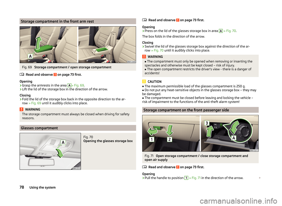
Storage compartment in the front arm restFig. 69
Storage compartment / open storage compartment
Read and observe
on page 73 first.
Opening
›
Grasp the armrests in the area
A
» Fig. 69 .
›
Lift the lid of the storage box in the direction of the arrow.
Closing
›
Fold the lid of the storage box back in the opposite direction to the ar-
row » Fig. 69 until it audibly clicks into place.
WARNINGThe storage compartment must always be closed when driving for safety
reasons.
Glasses compartment
Fig. 70
Opening the glasses storage box
Read and observe on page 73 first.
Opening
›
Press on the lid of the glasses storage box in area
A
» Fig. 70 .
The box folds in the direction of the arrow.
Closing
›
Swivel the lid of the glasses storage box against the direction of the ar-
row » Fig. 70 until it audibly clicks into place.
WARNING■
The compartment must only be opened when removing or inserting the
spectacles and otherwise must be kept closed – risk of injury.■
The open compartment restricts the driver's view - there is a danger of
accidents!
CAUTION
■ The maximum permissible load of the glasses compartment is 250 g.■Do not put any heat-sensitive objects in the glasses storage box – they may
be damaged.■
The compartment must be closed before leaving and locking the vehicle –
risk of impairment to the functions of the anti-theft alarm system!
Storage compartment on the front passenger side
Fig. 71
Open storage compartment / close storage compartment and
open air supply
Read and observe
on page 73 first.
Opening
›
Pull the handle to position
1
» Fig. 71 in the direction of the arrow.
78Using the system
Page 82 of 200
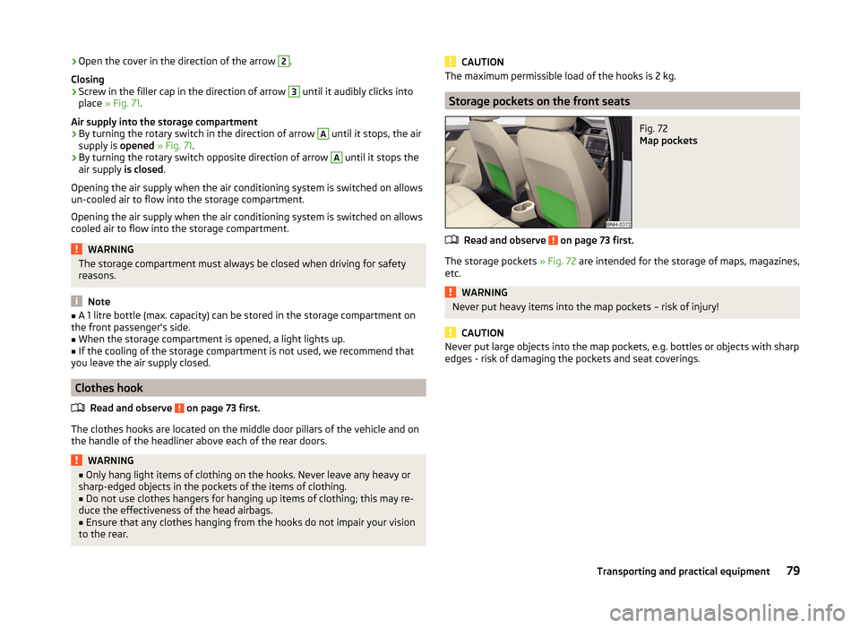
›Open the cover in the direction of the arrow 2.
Closing›
Screw in the filler cap in the direction of arrow
3
until it audibly clicks into
place » Fig. 71 .
Air supply into the storage compartment
›
By turning the rotary switch in the direction of arrow
A
until it stops, the air
supply is opened » Fig. 71 .
›
By turning the rotary switch opposite direction of arrow
A
until it stops the
air supply is closed.
Opening the air supply when the air conditioning system is switched on allows un-cooled air to flow into the storage compartment.
Opening the air supply when the air conditioning system is switched on allows cooled air to flow into the storage compartment.
WARNINGThe storage compartment must always be closed when driving for safety
reasons.
Note
■ A 1 litre bottle (max. capacity) can be stored in the storage compartment on
the front passenger's side.■
When the storage compartment is opened, a light lights up.
■
If the cooling of the storage compartment is not used, we recommend that
you leave the air supply closed.
Clothes hook
Read and observe
on page 73 first.
The clothes hooks are located on the middle door pillars of the vehicle and on
the handle of the headliner above each of the rear doors.
WARNING■ Only hang light items of clothing on the hooks. Never leave any heavy or
sharp-edged objects in the pockets of the items of clothing.■
Do not use clothes hangers for hanging up items of clothing; this may re-
duce the effectiveness of the head airbags.
■
Ensure that any clothes hanging from the hooks do not impair your vision
to the rear.
CAUTIONThe maximum permissible load of the hooks is 2 kg.
Storage pockets on the front seats
Fig. 72
Map pockets
Read and observe on page 73 first.
The storage pockets » Fig. 72 are intended for the storage of maps, magazines,
etc.
WARNINGNever put heavy items into the map pockets – risk of injury!
CAUTION
Never put large objects into the map pockets, e.g. bottles or objects with sharp
edges - risk of damaging the pockets and seat coverings.79Transporting and practical equipment
Page 83 of 200
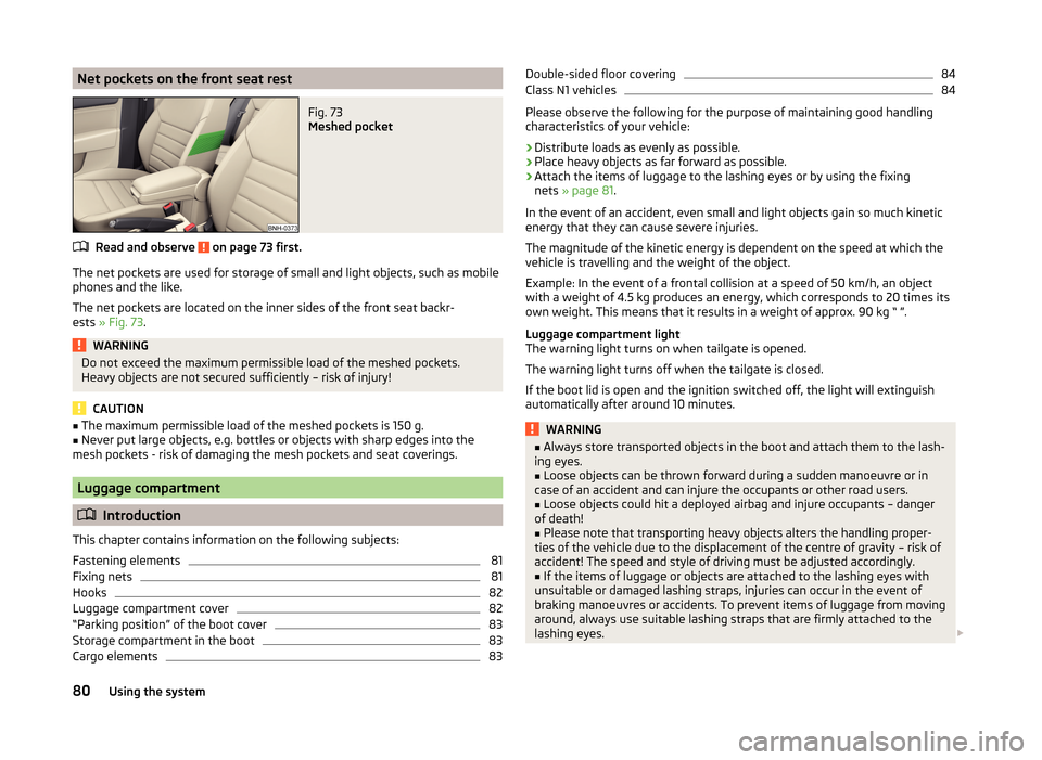
Net pockets on the front seat restFig. 73
Meshed pocket
Read and observe on page 73 first.
The net pockets are used for storage of small and light objects, such as mobile
phones and the like.
The net pockets are located on the inner sides of the front seat backr-
ests » Fig. 73 .
WARNINGDo not exceed the maximum permissible load of the meshed pockets.
Heavy objects are not secured sufficiently – risk of injury!
CAUTION
■ The maximum permissible load of the meshed pockets is 150 g.■Never put large objects, e.g. bottles or objects with sharp edges into the
mesh pockets - risk of damaging the mesh pockets and seat coverings.
Luggage compartment
Introduction
This chapter contains information on the following subjects:
Fastening elements
81
Fixing nets
81
Hooks
82
Luggage compartment cover
82
“Parking position” of the boot cover
83
Storage compartment in the boot
83
Cargo elements
83Double-sided floor covering84Class N1 vehicles84
Please observe the following for the purpose of maintaining good handling
characteristics of your vehicle:
›
Distribute loads as evenly as possible.
›
Place heavy objects as far forward as possible.
›
Attach the items of luggage to the lashing eyes or by using the fixing
nets » page 81 .
In the event of an accident, even small and light objects gain so much kinetic
energy that they can cause severe injuries.
The magnitude of the kinetic energy is dependent on the speed at which the
vehicle is travelling and the weight of the object.
Example: In the event of a frontal collision at a speed of 50 km/h, an object
with a weight of 4.5 kg produces an energy, which corresponds to 20 times its
own weight. This means that it results in a weight of approx. 90 kg “ ”.
Luggage compartment light
The warning light turns on when tailgate is opened.
The warning light turns off when the tailgate is closed.
If the boot lid is open and the ignition switched off, the light will extinguish
automatically after around 10 minutes.
WARNING■ Always store transported objects in the boot and attach them to the lash-
ing eyes.■
Loose objects can be thrown forward during a sudden manoeuvre or in
case of an accident and can injure the occupants or other road users.
■
Loose objects could hit a deployed airbag and injure occupants – danger
of death!
■
Please note that transporting heavy objects alters the handling proper-
ties of the vehicle due to the displacement of the centre of gravity – risk of
accident! The speed and style of driving must be adjusted accordingly.
■
If the items of luggage or objects are attached to the lashing eyes with
unsuitable or damaged lashing straps, injuries can occur in the event of
braking manoeuvres or accidents. To prevent items of luggage from moving
around, always use suitable lashing straps that are firmly attached to the
lashing eyes.
80Using the system
Page 84 of 200
WARNING (Continued)■The transported items must be stowed in such a way that no objects are
able to slip forward on sudden driving or braking manoeuvres – risk of in-
jury!■
When transporting objects in the luggage compartment that has been en-
larged by folding the rear seats forward, ensure the safety of the passen-
gers transported on the other rear seats » page 11, Correct seated position
for the passengers in the rear seats .
■
If the rear seat next to the folded forward seat is occupied, ensure maxi-
mum safety, e.g. by placing the goods to be transported in such a way that
the seat is prevented from folding back in case of a rear collision.
■
Do not drive with the luggage compartment lid open or unlatched, other-
wise exhaust gases may get into the interior of the vehicle – risk of poison-
ing!
■
Do not exceed the permissible axle loads and permissible gross weight of
the vehicle – risk of accident!
■
Do not transport people in the boot!
CAUTION
■ Please ensure that the heating elements for the rear window heater are not
damaged as a result of abrasive objects.■
Tyre pressure must be adjusted to the load » page 149.
Fastening elements
Fig. 74
Fasteners
Read and observe and on page 80 first.
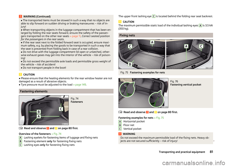
Overview of the fasteners » Fig. 74
Lashing eyelets for fastening items of luggage and fixing nets
Fastening element only for fastening fixing nets
Lashing eyes only for fastening fixing nets
ABCThe upper front lashing eye C is located behind the folding rear seat backrest.
CAUTION
The maximum permissible static load of the individual lashing eyes A is 3.5 kN
(350 kg).
Fixing nets
Fig. 75
Fastening examples for nets
Fig. 76
Fastening vertical pocket
Read and observe and on page 80 first.
Fastening examples for nets » Fig. 75
Horizontal pocket
Floor net
Vertical pocket
WARNINGDo not exceed the maximum permissible load of the fixing nets. Heavy ob-
jects are not secured sufficiently – risk of injury! ABC81Transporting and practical equipment
Page 85 of 200
CAUTION■The maximum permissible load of the fixing nets is 1.5 kg.■Do not place any sharp objects in the nets – risk of net damage.
Hooks
Fig. 77
Hooks
Read and observe and on page 80 first.
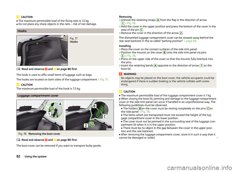
The hook is used to affix small items of luggage such as bags.
The hooks are located on both sides of the luggage compartment » Fig. 77.
CAUTION
The maximum permissible load of the hook is 7.5 kg.
Luggage compartment cover
Fig. 78
Removing the boot cover
Read and observe
and on page 80 first.
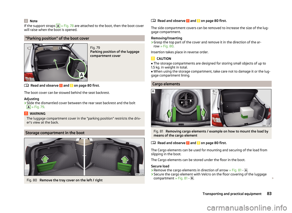
The boot cover can be removed if you want to transport bulky goods.
Removing›Unhook the retaining straps A from the flap in the direction of arrow1
» Fig. 78 .
›
Hold the cover in the upper position and press the bottom of the cover in the
area of the pin
C
.
›
Remove the cover in the direction of the arrow
2
.
The dismantled luggage compartment cover can be stowed away behind the
rear seat backrest in the so called “parking position” » page 83.
Installing
›
Place the cover on the contact surfaces of the side trim panel.
›
Position the mounts on the cover
B
onto the side trim panel via pins
C
» Fig. 78 .
›
Press on the upper side of the cover so that the mounts fully interlock into
the pins.
›
Insert the retaining bands
A
opposite to the direction of arrow
1
on the
boot lid.
WARNINGNo objects may be placed on the boot cover, the vehicle occupants could be
endangered if there is sudden braking or the vehicle collides with some-
thing.
CAUTION
■ The maximum permissible load of the luggage compartment cover is 1 kg.■When closing the boot lid, jamming and damage to the luggage compartment
cover or the side trim panel can occur if handled in an unprofessional way. The
following guidelines must be observed. ■ The holders B
on the cover must be resting completely on the pins
C
on
the side panel » Fig. 78.
■ The items which are transported must not exceed the height of the lug-
gage compartment cover in the lower position.
■ The cover must not be jammed in the surrounding seal of the luggage com-
partment lid when it is in the upper position.
■ There must be no object in the gap between the cover in the upper posi-
tion and the rear backrest.
■
After removing the luggage compartment cover, store it in such a way that it
cannot be damaged or soiled.
82Using the system
Page 86 of 200
NoteIf the support straps A » Fig. 78 are attached to the boot, then the boot cover
will raise when the boot is opened.
“Parking position” of the boot cover
Fig. 79
Parking position of the luggage
compartment cover
Read and observe and on page 80 first.
The boot cover can be stowed behind the seat backrest.
Adjusting
›
Slide the dismantled cover between the rear seat backrest and the bolt
A
» Fig. 79 .
WARNINGThe luggage compartment cover in the “parking position” restricts the driv-
er's view at the back.
Storage compartment in the boot
Fig. 80
Remove the tray cover on the left / right
Read and observe and on page 80 first.
The side compartment covers can be removed to increase the size of the lug-gage compartment.
Removing/Inserting
›
Grasp the top part of the cover and remove it in the direction of the ar-
row » Fig. 80 .
Insertion takes place in reverse order.
CAUTION
■ The storage compartments are designed for storing small objects of up to
1.5 kg. in weight in total.■
When using the storage compartment, take care not to damage it or the lug-
gage compartment lining.
Cargo elements
Fig. 81
Removing cargo elements / example on how to mount the load by
means of the cargo element
Read and observe
and on page 80 first.
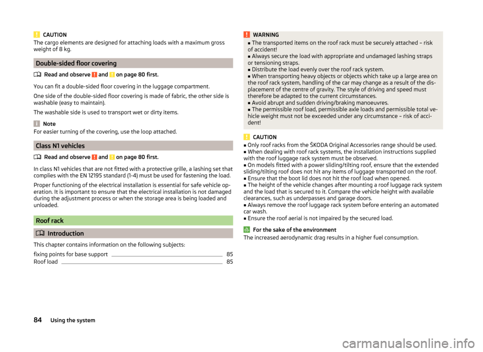
The Cargo elements can be used for mounting and securing of the load from
slipping in the boot.
The Cargo elements can be stored under the floor in the boot.
Secure load
›
Remove the cargo elements in direction of arrow » Fig. 81 -
.
›
Secure the cargo element with Velcro on the floor covering of the luggage
compartment » Fig. 81 -
.
83Transporting and practical equipment
Page 87 of 200
CAUTIONThe cargo elements are designed for attaching loads with a maximum gross
weight of 8 kg.
Double-sided floor covering
Read and observe
and on page 80 first.
You can fit a double-sided floor covering in the luggage compartment.
One side of the double-sided floor covering is made of fabric, the other side is
washable (easy to maintain).
The washable side is used to transport wet or dirty items.
Note
For easier turning of the covering, use the loop attached.
Class N1 vehicles
Read and observe
and on page 80 first.
In class N1 vehicles that are not fitted with a protective grille, a lashing set that
complies with the EN 12195 standard (1-4) must be used for fastening the load.
Proper functioning of the electrical installation is essential for safe vehicle op-
eration. It is important to ensure that the electrical installation is not damaged
during the adjustment process or when the storage area is being loaded and
unloaded.
Roof rack
Introduction
This chapter contains information on the following subjects:
fixing points for base support
85
Roof load
85WARNING■ The transported items on the roof rack must be securely attached – risk
of accident!■
Always secure the load with appropriate and undamaged lashing straps
or tensioning straps.
■
Distribute the load evenly over the roof rack system.
■
When transporting heavy objects or objects which take up a large area on
the roof rack system, handling of the car may change as a result of the dis-
placement of the centre of gravity. The style of driving and speed must
therefore be adapted to the current circumstances.
■
Avoid abrupt and sudden driving/braking manoeuvres.
■
The permissible roof load, permissible axle loads and permissible total ve-
hicle weight must not be exceeded under any circumstance – risk of acci-
dent!
CAUTION
■ Only roof racks from the ŠKODA Original Accessories range should be used.■When dealing with roof rack systems, the installation instructions supplied
with the roof luggage rack system must be observed.■
On models fitted with a power sliding/tilting roof, ensure that the extended
sliding/tilting roof does not hit any items of luggage transported on the roof.
■
Ensure that the boot lid does not hit the roof load when opened.
■
The height of the vehicle changes after mounting a roof luggage rack system
and the load that is secured to it. Compare the vehicle height with available
clearances, such as underpasses and garage doors.
■
Always remove the roof luggage rack system before entering an automated
car wash.
■
Ensure the roof aerial is not impaired by the secured load.
For the sake of the environment
The increased aerodynamic drag results in a higher fuel consumption.84Using the system
Page 88 of 200
fixing points for base supportFig. 82
Attachment points
Read and observe
and on page 84 first.
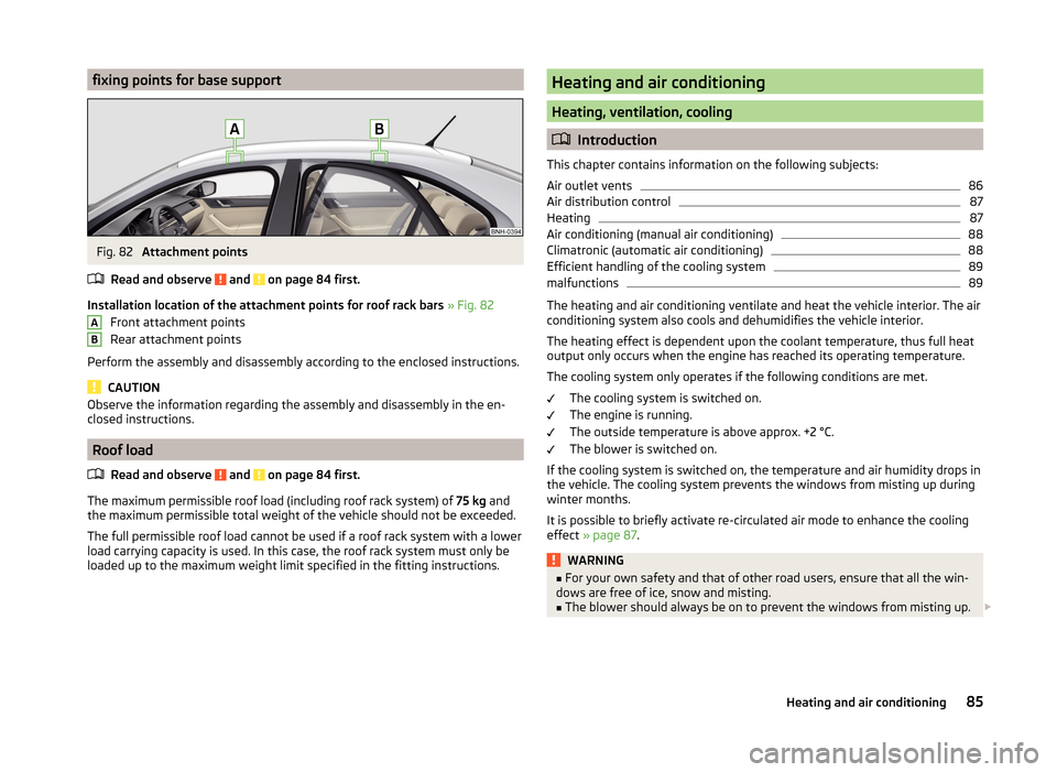
Installation location of the attachment points for roof rack bars » Fig. 82
Front attachment points
Rear attachment points
Perform the assembly and disassembly according to the enclosed instructions.
CAUTION
Observe the information regarding the assembly and disassembly in the en-
closed instructions.
Roof load
Read and observe
and on page 84 first.
The maximum permissible roof load (including roof rack system) of 75 kg and
the maximum permissible total weight of the vehicle should not be exceeded.
The full permissible roof load cannot be used if a roof rack system with a lower
load carrying capacity is used. In this case, the roof rack system must only be
loaded up to the maximum weight limit specified in the fitting instructions.
ABHeating and air conditioning
Heating, ventilation, cooling
Introduction
This chapter contains information on the following subjects:
Air outlet vents
86
Air distribution control
87
Heating
87
Air conditioning (manual air conditioning)
88
Climatronic (automatic air conditioning)
88
Efficient handling of the cooling system
89
malfunctions
89
The heating and air conditioning ventilate and heat the vehicle interior. The air
conditioning system also cools and dehumidifies the vehicle interior.
The heating effect is dependent upon the coolant temperature, thus full heat
output only occurs when the engine has reached its operating temperature.
The cooling system only operates if the following conditions are met. The cooling system is switched on.
The engine is running.
The outside temperature is above approx. +2 °C.
The blower is switched on.
If the cooling system is switched on, the temperature and air humidity drops in
the vehicle. The cooling system prevents the windows from misting up during
winter months.
It is possible to briefly activate re-circulated air mode to enhance the cooling
effect » page 87 .
WARNING■
For your own safety and that of other road users, ensure that all the win-
dows are free of ice, snow and misting.■
The blower should always be on to prevent the windows from misting up.
85Heating and air conditioning
Page 89 of 200
WARNING (Continued)■Under certain circumstances, air at a temperature of about 5 °C can flow
out of the vents when the cooling system is switched on.■
To reduce health risks (e.g. common colds), the following instructions for
the use of the cooling system are to be observed. ■The difference between the indoor temperature and the outdoor air
temperature should not be greater than about 5 ° C.
■ The cooling system is to be turned off about 10 minutes before the end
of the journey.
■ Once a year, a disinfection of the air conditioner or the Climatronic is to
be carried out by a specialist company.
CAUTION
■ The air inlet in front of the windscreen must be free from ice, snow or leaves,
for example, to ensure that the heating and cooling system works properly.■
After switching on the cooling Condensation from the evaporator of the air
conditioning may drip down and form a puddle below the vehicle. This is not a
leak!
■
If the coolant temperature is too high, the cooling system is switched off to
ensure that the engine cools down.
Note
The used air streams out through the vents in the luggage compartment.
Air outlet vents
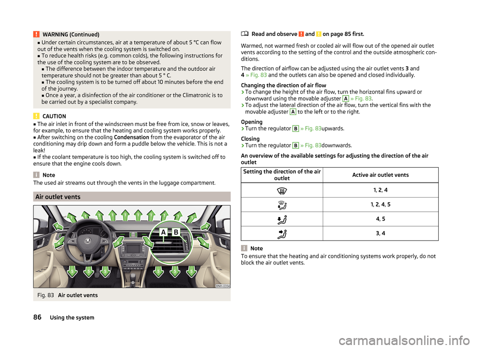
Fig. 83
Air outlet vents
Read and observe and on page 85 first.
Warmed, not warmed fresh or cooled air will flow out of the opened air outlet vents according to the setting of the control and the outside atmospheric con-
ditions.
The direction of airflow can be adjusted using the air outlet vents 3 and
4 » Fig. 83 and the outlets can also be opened and closed individually.
Changing the direction of air flow
›
To change the height of the air flow, turn the horizontal fins upward or
downward using the movable adjuster
A
» Fig. 83 .
›
To adjust the lateral direction of the air flow, turn the vertical fins with the
movable adjuster
A
to the left or to the right.
Opening
›
Turn the regulator
B
» Fig. 83 upwards.
Closing
›
Turn the regulator
B
» Fig. 83 downwards.
An overview of the available settings for adjusting the direction of the air
outlet
Setting the direction of the air outletActive air outlet vents1, 2 , 41, 2 , 4 , 54 , 53 , 4
Note
To ensure that the heating and air conditioning systems work properly, do not
block the air outlet vents.86Using the system
Page 90 of 200
Air distribution controlRead and observe
and on page 85 first.
Recirculated air mode mostly prevents polluted air outside the vehicle fromgetting into the vehicle, for example when driving through a tunnel or when
standing in a traffic jam.
In recirculated air mode air is sucked out of the interior of the vehicle and then
fed back into the interior.
Heating and air conditioning (manual air conditioning)
To turn the recirculation mode on or off, press the Symbol key
.
The air recirculation mode is automatically turned off by turning the air distri-
bution control
C
to position
» Fig. 84 on page 87 or » Fig. 85 on
page 88 .
Recirculated air mode can be switched on again from this setting by repeatedly
pressing the symbol button .
Climatronic (automatic air conditioning)
To switch on press the Symbol key
. The symbol
(pos.
7
» Fig. 86 on
page 88 ) appears in the display.
To switch off press the symbol key
again. The
symbol in the display
goes out.
WARNINGThe recirculation system cannot be switched on for a longer period of time,
because there is no supply of fresh air from the outside. “Stale air” may re-
sult in fatigue in the driver and occupants, reduce attention levels and also
cause the windows to mist up. The risk of having an accident increases.
Switch off recirculated air mode as soon as the windows start to mist up.
CAUTION
We recommend not smoking in the vehicle when the recirculating air operation
is switched on. The smoke sucked from inside the vehicle is deposited on the
evaporator of the air conditioner. This produces a permanent odour when the
air conditioning system is operating which can only be eliminated through con-
siderable effort and expense (replacement of compressor).NoteIf recirculated air mode is switched on for around 15 minutes, the symbol
will begin to flash in the Climatronic display as a sign that the recirculated air
mode is switched on long-term. If the recirculated air mode is not switched off,
the symbol flashes for around 5 minutes.
Heating
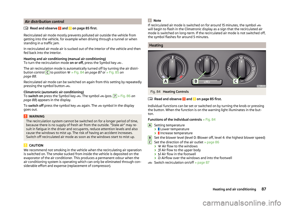
Fig. 84
Heating Controls
Read and observe
and on page 85 first.
Individual functions can be set or switched on by turning the knob or pressing the button. When the function is on the warning light illuminates in the but-
ton.
Functions of the individual controls » Fig. 84
Setting temperature ›
Lower temperature
›
Increase temperature
Set the blower level (level 0: Blower off, level 4: the highest blower speed)
Set the direction of the air outlet » page 86
›
Air flow to the windows
›
Air flow to the upper body
›
Air flow in the footwell
›
Airflow over the windows and into the footwell
Switch recirculation on/off » page 87
ABC87Heating and air conditioning