clutch SKODA RAPID 2014 1.G Owner's Manual
[x] Cancel search | Manufacturer: SKODA, Model Year: 2014, Model line: RAPID, Model: SKODA RAPID 2014 1.GPages: 200, PDF Size: 25.57 MB
Page 10 of 200
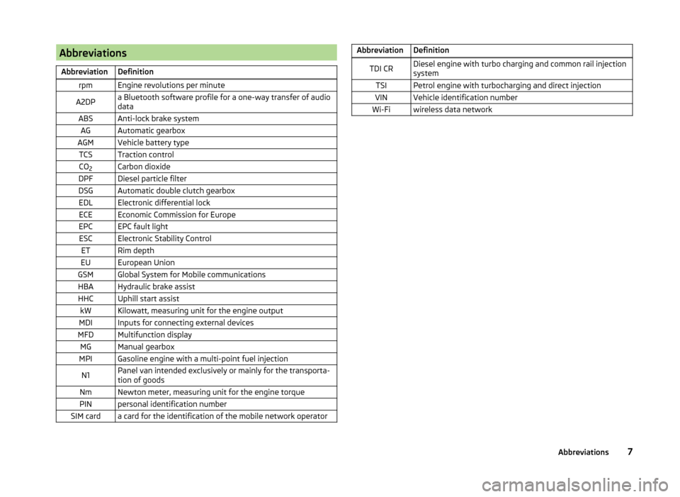
AbbreviationsAbbreviationDefinitionrpmEngine revolutions per minuteA2DPa Bluetooth software profile for a one-way transfer of audio
dataABSAnti-lock brake systemAGAutomatic gearboxAGMVehicle battery typeTCSTraction controlCO 2Carbon dioxideDPFDiesel particle filterDSGAutomatic double clutch gearboxEDLElectronic differential lockECEEconomic Commission for EuropeEPCEPC fault lightESCElectronic Stability ControlETRim depthEUEuropean UnionGSMGlobal System for Mobile communicationsHBAHydraulic brake assistHHCUphill start assistkWKilowatt, measuring unit for the engine outputMDIInputs for connecting external devicesMFDMultifunction displayMGManual gearboxMPIGasoline engine with a multi-point fuel injectionN1Panel van intended exclusively or mainly for the transporta-
tion of goodsNmNewton meter, measuring unit for the engine torquePINpersonal identification numberSIM carda card for the identification of the mobile network operatorAbbreviationDefinitionTDI CRDiesel engine with turbo charging and common rail injection
systemTSIPetrol engine with turbocharging and direct injectionVINVehicle identification numberWi-Fiwireless data network7Abbreviations
Page 13 of 200
WARNING■Always assume the correct seated position before setting off and do not
change this position while driving. Also advise your passengers to adopt
the correct seated position and not to change this position while the car is
moving.■
Maintain a distance of at least 25 cm to the steering wheel. Not maintain-
ing this minimum distance will mean that the airbag system will not be able
to properly protect you – hazard!
■
When driving, hold the steering wheel with both hands firmly on the out-
er edge in the “9 o'clock” and “3 o'clock” position. Never hold the steering
wheel in the “12 o'clock” position or in any other way (e.g. in the middle or
inner edge of the steering wheel). In such cases, you could severely injure
the arms, hands and head when the driver airbag is deployed.
■
Ensure that there are no objects in the driver's footwell as they may get
caught behind the pedals when driving or applying the braking. You would
then no longer be able to operate the clutch, brake or acceleration pedals.
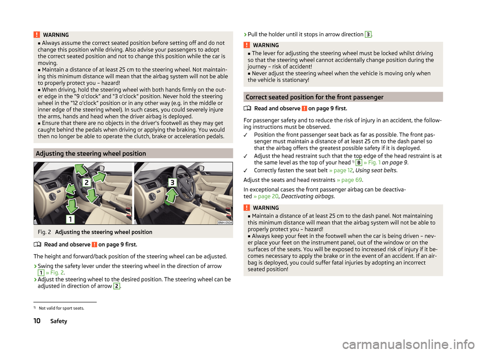
Adjusting the steering wheel position
Fig. 2
Adjusting the steering wheel position
Read and observe
on page 9 first.
The height and forward/back position of the steering wheel can be adjusted.
›
Swing the safety lever under the steering wheel in the direction of arrow
1
» Fig. 2 .
›
Adjust the steering wheel to the desired position. The steering wheel can be
adjusted in direction of arrow
2
.
› Pull the holder until it stops in arrow direction 3.WARNING■
The lever for adjusting the steering wheel must be locked whilst driving
so that the steering wheel cannot accidentally change position during the
journey – risk of accident!■
Never adjust the steering wheel when the vehicle is moving only when
the vehicle is stationary!
Correct seated position for the front passenger
Read and observe
on page 9 first.
For passenger safety and to reduce the risk of injury in an accident, the follow-ing instructions must be observed.
Position the front passenger seat back as far as possible. The front pas-
senger must maintain a distance of at least 25 cm to the dash panel so
that the airbag offers the greatest possible safety if it is deployed.
Adjust the head restraint such that the top edge of the head restraint is at
the same level as the top of your head 1)
B
» Fig. 1 on page 9 .
Correctly fasten the seat belt » page 12, Using seat belts .
Adjust the seats and head restraints » page 69.
In exceptional cases the front passenger airbag can be deactiva-
ted » page 20 , Deactivating airbags .
WARNING■
Maintain a distance of at least 25 cm to the dash panel. Not maintaining
this minimum distance will mean that the airbag system will not be able to
properly protect you – hazard!■
Always keep your feet in the footwell when the car is being driven – nev-
er place your feet on the instrument panel, out of the window or on the
surfaces of the seats. You will be exposed to increased risk of injury if it be-
comes necessary to apply the brake or in the event of an accident. If an air-
bag is deployed, you could suffer fatal injuries by adopting an incorrect
seated position!
1)
Not valid for sport seats.
10Safety
Page 37 of 200
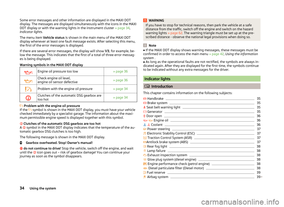
Some error messages and other information are displayed in the MAXI DOT
display. The messages are displayed simultaneously with the icons in the MAXI
DOT display or with the warning lights in the instrument cluster » page 34,
Indicator lights .
The menu item Vehicle status is shown in the main menu of the MAXI DOT
display whenever at least one fault message exists. After selecting this menu,
the first of the error messages is displayed.
If there are several error messages, the display will show 1/3, for example, be-
low the message. This indicates that the first of a total of three error messag-
es is being displayed.
Warning symbols in the MAXI DOT displayEngine oil pressure too low» page 36Check engine oil level,
engine oil sensor defective» page 36Problem with the engine oil pressure» page 34Clutches of the automatic DSG gearbox are
too hot» page 34
Problem with the engine oil pressure
If the symbol is shown in the MAXI DOT display, you must have your vehicle
checked immediately by a specialist garage. The information about the maxi-
mum permissible engine speed is displayed together with this symbol.
Clutches of the automatic DSG gearbox are too hot
A symbol in the MAXI DOT display indicates that the temperature of the au-
tomatic gearbox DSG clutches is too high.
The following message is shown in the MAXI DOT display. Gearbox overheated. Stop! Owner's manual!
do not continue to drive! Stop the vehicle, switch off the engine, and wait
until the icon goes out – risk of gearbox damage! You can continue your
journey as soon as the symbol disappears.
WARNINGIf you have to stop for technical reasons, then park the vehicle at a safe
distance from the traffic, switch off the engine and switch on the hazard
warning lights » page 62. The warning triangle must be set up at the pre-
scribed distance - observe the national legal provisions when doing so.
Note
■ If the MAXI DOT display shows warning messages, these messages must be
confirmed in order to access the main menu » page 42, Using the information
system .■
As long as the operational faults are not rectified, the symbols are always in-
dicated again. After they are displayed for the first time, the symbols continue
to be indicated without any extra messages for the driver.
Indicator lights
Introduction
This chapter contains information on the following subjects:
Handbrake
35
Brake system
35
Seat belt warning light
35
Generator
35
Door open
36
Engine oil
36
Coolant
36
Power steering
37
Electronic Stability Control (ESC)
37
Traction Control System (ASR)
37
Antilock brake system (ABS)
37
Rear fog light
38
Lamp failure
38
Exhaust inspection system
38
Glow plug system (diesel engine)
38
Engine performance check (petrol engine)
38
Diesel particulate filter (Diesel motor)
38
Fuel reserve
39
Airbag system
39
34Using the system
Page 76 of 200
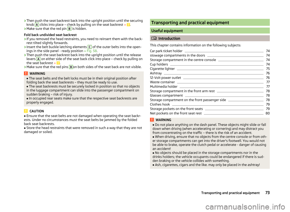
›Then push the seat backrest back into the upright position until the securing
knob A clicks into place – check by pulling on the seat backrest » .›
Make sure that the red pin
B
is hidden.
Fold back undivided seat backrest
›
If you removed the head restraints, you need to reinsert them with the back-
rest tilted slightly forwards.
›
Insert the belt buckle latching elements
C
of the outer belts into the open-
ings in the side panel - ready position » Fig. 58.
›
Then push the seat backrest back into the upright position until the release
levers
A
on either side of the seat back click into place – check by pulling on
the seat backrest » .
›
Make sure that the red pins
B
on both sides of the seat back are not visible.
WARNING■
The seat belts and the belt locks must be in their original position after
folding back the seat backrests – they must be ready to use.■
The seat backrests must be securely locked in position so that no objects
in the luggage compartment can slide into the passenger compartment on
sudden braking – risk of injury.
■
In occupied rear seats make sure that the respective seat backrests are
properly engaged.
CAUTION
■ Ensure that the seat belts are not damaged when operating the seat backr-
ests. Under no circumstances must the seat belts be jammed by the folded
back seat backrests.■
Store the head restraints that were removed in such a way that they are not
damaged or soiled.
Transporting and practical equipment
Useful equipment
Introduction
This chapter contains information on the following subjects:
Car park ticket holder
74
stowage compartments in the doors
74
Storage compartment in the centre console
74
Cup holders
74
Cigarette lighter
75
Ashtray
76
12-Volt power outlet
76
Waste container
77
Multimedia holder
77
Storage compartment in the front arm rest
78
Glasses compartment
78
Storage compartment on the front passenger side
78
Clothes hook
79
Storage pockets on the front seats
79
Net pockets on the front seat rest
80WARNING■ Do not place anything on the dash panel. These objects might slide or fall
down when driving (when accelerating or cornering) and may distract you
from concentrating on the traffic – there is the risk of an accident.■
When driving, ensure that no objects from the centre console or from oth-
er storage compartments can get into the driver's footwell. You would not
be able to brake, operate the clutch pedal or accelerate - danger of causing
an accident!
■
No objects should be placed in the storage compartments nor in the
drinks holders; the vehicle occupants could be endangered if there is sud-
den braking or the vehicle collides with something.
■
Ash, cigarettes, cigars and the like. may only be placed in the ashtray!
73Transporting and practical equipment
Page 104 of 200

Lock/unlock steering lockRead and observe
and on page 100 first.
The steering lock (steering lock) deters any attempted theft of your vehicle.
Locking
›
Withdraw the ignition key.
›
Turn the steering wheel to the left or right until the steering lock clicks into
place.
Unlocking
›
Insert the key into the ignition lock.
›
Switch on the ignition » page 101.
The steering lock is unlocked.
If the ignition switch cannot be turned on, then turn the steering wheel back and forth slightly and thereby unlock the steering lock.
Ignition on / off and start the engine
Fig. 91
Positions of the vehicle key in the ignition lock
Read and observe and on page 100 first.
Positions of the vehicle key in the ignition lock » Fig. 91
Ignition switched off, engine switched off
Ignition switched on
Starting engine
Switching ignition on/off
›
Turn key to position
2
.
The ignition is switched on.
›
Turn key to position
1
.
123The ignition is switched off.
Procedure for starting the engine›
Firmly apply the handbrake.
›
For vehicles with manual transmission , shift gear stick to neutral, depress
the clutch pedal and hold it there until the engine starts.
›
On vehicles with automatic transmission , place the selector lever in position
P or N and depress the brake pedal until the engine starts.
›
Turn the key into position
3
to the stop and release immediately after the
engine has been started – do not apply the accelerator.
After letting go, the vehicle key will return to position
2
.
For vehicles with diesel engines the glow plug warning light
goes on during
starting. The engine can be started after the indicator light goes out.
If the engine does not start within 10 seconds, turn the key to position
1
. Re-
peat the start-up process after approx. half a minute.
Vehicles with the START-STOP system and manual gearbox
The engine will not start if the clutch pedal is not depressed.
The following message is shown in the information cluster display. Depress clutch to start!
CLUTCH
Vehicles with the START-STOP system and automatic gearbox
The engine will not start if the brake pedal is not depressed.
The following message is shown in the information cluster display. Depress brake to start.
BRAKE
Note
■ The engine running noises may louder at first be louder for a short time after
starting the cold engine. This is quite normal and is not an operating problem.■
You should not switch on any major electrical components during the heat-
ing period otherwise the vehicle battery will be drained unnecessarily.
Switching off the engine
Read and observe
and on page 100 first.
›
Stop the vehicle » page 103, Parking .
›
Turn key to position
1
» Fig. 91 on page 101 .
101Starting-off and Driving
Page 105 of 200
The engine and the ignition are switched off simultaneously.
For vehicles with automatic transmission, the ignition key can only be removed if the selector lever is in position P .
CAUTION
Do not switch the engine off immediately at the end of your journey after the
engine has been operated over a prolonged period at high loads but leave it to
run at an idling speed for about 1 minute. This prevents any possible accumula-
tion of heat when the engine is switched off.
Note
After switching off the ignition, the radiator fan may intermittently continue to
operate for approx. 10 minutes.
Brakes and parking
Introduction
This chapter contains information on the following subjects:
Information on braking
102
Handbrake
103
Parking
103WARNING■ Greater physical effort is required for braking when the engine is switch-
ed off – risk of accident!■
The clutch pedal must be actuated when braking on a vehicle with man-
ual transmission, when the vehicle is in gear and at low revs. Otherwise,
the functionality of the brake system may be impaired – risk of accident!
■
When leaving the vehicle, never leave persons who might, for example,
release the handbrake or take the vehicle out of gear unattended in the ve-
hicle. The vehicle could then start to move – risk of accident!
■
Observe the recommendations on the new brake pads » page 107, New
brake pads .
CAUTION
Never let the brakes slip with light pressure on the pedal if braking is not nec-
essary. This causes the brakes to overheat and can also result in a longer brak-
ing distance and excessive wear.Information on braking
Read and observe
and on page 102 first.
Wear-and-tear
The wear of the brake pads is dependent on the operating conditions and driv-
ing style.
The brake pads wear more quickly if a lot of journeys are completed in towns
and over short distances or if a very sporty style of driving is adopted.
Under these severe conditions , the thickness of the brake pads must also be
checked by a specialist garage between service intervals.
Wet roads or road salt
The performance of the brakes can be delayed as the brake discs and brake
pads may be moist or have a coating of ice or layer of salt on them in winter.
The brakes are cleaned and dried by applying the brakes several times »
.
Corrosion
Corrosion on the brake discs and dirt on the bake pads occur if the vehicle has
been parked for a long period and if you do not make much use of the braking
system. The brakes are cleaned by applying the brakes several times »
.
Long or steep slopes
Before travelling a long distance with a steep gradient, reduce speed and shift
into the next lowest gear. As a result, the braking effect of the engine will be
used, reducing the load on the brakes. Any additional braking should be com-
pleted intermittently, not continuously.
Emergency brake display
If the brakes are applied in full and the control unit for the braking system con-
siders the situation to be dangerous for the following traffic, the brake light
flashes automatically.
After the speed was reduced below around 10 km/h or the vehicle was stop-
ped, the brake light stops flashing and the hazard warning light system
switches on. The hazard warning light system is switched off automatically af- ter accelerating or driving off again.
Faults in the brake surface
If it is found that the braking distance has suddenly become longer and that
the brake pedal can be depressed further, the brake system may be faulty.
Visit a specialist garage immediately and adjust your style of driving appropri-
ately, as you will not know the exact extent of the damage.
102Driving
Page 107 of 200
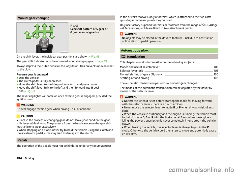
Manual gear changingFig. 93
Gearshift pattern of 5 gear or
6 gear manual gearbox
On the shift lever, the individual gear positions are shown » Fig. 93.
The gearshift indicator must be observed when changing gear » page 43.
Always depress the clutch pedal all the way down. This prevents uneven wear
to the clutch.
Reverse gear is engaged
›
Stop the vehicle.
›
The clutch pedal is fully depressed.
›
Move the shift lever to the idle position switch and press down.
›
Move the shift lever fully to the left and then forward into R posi-
tion » Fig. 93 .
The reversing lights will come on once reverse gear is engaged, provided the ignition is on.
WARNINGNever engage reverse gear when driving – risk of accident!
CAUTION
■ If not in the process of changing gear, do not leave your hand on the gear-
shift lever while driving. The pressure from the hand can cause the gearshift
mechanism to wear excessively.■
When stopping on a slope, never try to hold the vehicle using the clutch and
the accelerator pedal – this may lead to damage to the clutch.
Pedals
The operation of the pedals must not be hindered under any circumstances!
In the driver's footwell, only a footmat, which is attached to the two corre-
sponding attachment points may be used.
Only use factory-supplied footmats or footmats from the range of ŠKODAOrigi-
nal Accessories, which are fitted to two attachment points.WARNINGNo objects may be placed in the driver's footwell – risk due to obstruction
or limitation of pedal operation!
Automatic gearbox
Introduction
This chapter contains information on the following subjects:
Modes and use of selector lever
105
Selector lever lock
105
Manual shifting of gears (Tiptronic)
106
Starting-off and driving
106
The automatic transmission performs automatic gear changes.
The modes of the automatic transmission can be adjusted by the driver by
means of the selector lever.
WARNING■ No throttle when it is set before starting the mode for moving forward
with the selector lever - there is a risk of accident!■
Never move the selector lever to mode R or P when driving – risk of acci-
dent!
■
When the vehicle is stationary and the engine is running, the vehicle must
be held in mode D, S or R with the brake pedal. Even when the engine is
idling, the power transmission is never completely interrupted – the vehicle
crawls.
■
When leaving the vehicle, the selector lever is always to put in the P
mode. Otherwise the vehicle could then start to move and potentially cause
an accident.
104Driving
Page 115 of 200

WARNINGIf the engine power and engine braking effect is insufficient to maintain
the set speed, vehicle operation must be taken over!
Operating Description
Fig. 99
Operating lever: Cruise control
system controls
Read and observe on page 111 first.
Overview of the control elements of the CCS » Fig. 99ADeactivate CCS (delete stored speed) Interrupt control (sprung position) Activate CCS (control deactivated)BTake control again a)
/ Increase speedCLaunch control / reduce speeda)
If no speed stored, the current speed is adopted.
After starting the system, the current speed is stored and the instrument clus-
ter lights up the indicator light
on.
After the interruption in control, the stored speed can be resumed by pressing
the
B
button.
Automatic control interruption
Automatic control interruption occurs if any of the following conditions are
met.
› By pressing the brake or clutch pedal.
› When one of the brake assist systems (e.g. ESC) intervenes.
› Through an airbag deployment.
WARNING■
Always deactivate the cruise control system after use to prevent the sys-
tem being switched on unintentionally.■
Control may only be resumed if the stored speed is not too high for the
current traffic conditions.
Note
During control, speed can be increased by pressing the accelerator pedal. Re-
leasing the accelerator pedal will cause the speed to drop again to the set
speed.
START-STOP
Introduction
This chapter contains information on the following subjects:
Operating conditions of the system
113
Operation in vehicles with manual gearbox
113
Operation in vehicles with automatic gearbox
113
System related automatic start-up
114
Manually deactivating/activating the system
114
Information messages
114
The START-STOP system (hereinafter referred to as the system) saves fuel and
reduces polluting emissions and CO 2 emissions by turning the engine off, e.g.
when stopping at traffic lights, and starting the engine again when moving off.
WARNING■ Never let the vehicle roll with the engine switched off.■The brake servo unit and power steering only operate if the engine is run-
ning.112Driving
Page 116 of 200

Operating conditions of the systemFig. 100
MAXI DOT display: Engine is au-
tomatically switched off / auto-
matic engine cut off is not possi-
ble
Read and observe on page 112 first.
For system-dependent automatic engine shutdown
to work, the following conditions must be met.
The driver's door is closed.
The driver has fastened the seat belt.
The bonnet is closed.
The driving speed was higher than 4 km/h after the last stop.
No trailer is coupled.
Some additional conditions for the system to function correctly cannot be in-
fluenced or recognised by the driver. Therefore, the system can react differ-
ently in situations which are identical from the driver's perspective.
If after stopping the car, the message START-STOP NOT POSSIBLE appears in
the segment display or the MAXI DOT display shows the
» Fig. 100 warning
sign, then the conditions for automatic engine shutdown are not being met.
Running the engine is essential for the following reasons, for example.
› The engine temperature for the proper function of the system has not yet
been reached.
› The charge state of the vehicle battery is too low.
› The current consumption is too high.
› High air-conditioning or heating capacity (high fan speed, big difference be-
tween the desired and actual interior temperature).
Note■ If the vehicle remains outdoors for a long time in minus temperatures or in
direct sunlight, it can take several hours until the internal temperature of the
vehicle battery reaches a suitable temperature for proper operation of the
START STOP system.■
If the driver's seat belt is removed for more than approx. 30 seconds or the
driver's door is opened during stop mode, the engine will have to be started
manually.
■
After the manual engine start and with a manual gearbox the automatic en-
gine shutdown can take place only when a minimum distance required for the
system function has been covered.
Operation in vehicles with manual gearbox
Read and observe
on page 112 first.
In compliance with the operating conditions, automatic engine shutdown / au-
tomatic engine start takes place as described.
Automatic engine shutdown
›
Stop the vehicle.
›
Put the gear stick into Neutral.
›
Release the clutch pedal.
Automatic engine shutdown takes place, segment display shows START-STOP
ACTIVE or the MAXI DOT display shows the warning sign
» Fig. 100 on
page 113 .
Automatic engine start
›
Depress the clutch pedal.
The automatic start procedure takes place again.
Operation in vehicles with automatic gearbox
Read and observe
on page 112 first.
In compliance with the operating conditions, automatic engine shutdown / au-
tomatic engine start takes place as described.
Automatic engine shutdown
›
Bring the vehicle to a stop and depress the brake pedal.
113Assist systems
Page 167 of 200
WARNING■Do not clamp the jump-start cable to the negative terminal of the dis-
charged battery. There is the risk of detonating gas seeping out the battery
being ignited by the strong spark which results from the engine being star-
ted.■
The non-insulated parts of the terminal clamps must never touch each
other – there is a risk of short circuit.
■
The jump-start cable connected to the positive terminal of the battery
must not come into contact with electrically conducting parts of the vehicle
– there is a risk of short circuit.
■
Route the jump-start cables so that they cannot be caught by any rotat-
ing parts in the engine compartment.
■
There must not be any contact between the two vehicles otherwise cur-
rent may flow as soon as the negative terminals are connected.
Towing the vehicle
Introduction
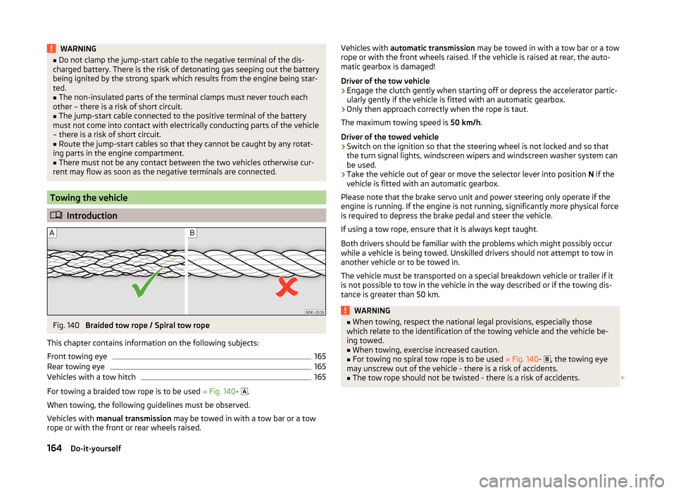
Fig. 140
Braided tow rope / Spiral tow rope
This chapter contains information on the following subjects:
Front towing eye
165
Rear towing eye
165
Vehicles with a tow hitch
165
For towing a braided tow rope is to be used » Fig. 140-
.
When towing, the following guidelines must be observed.
Vehicles with manual transmission may be towed in with a tow bar or a tow
rope or with the front or rear wheels raised.
Vehicles with automatic transmission may be towed in with a tow bar or a tow
rope or with the front wheels raised. If the vehicle is raised at rear, the auto-
matic gearbox is damaged!
Driver of the tow vehicle›
Engage the clutch gently when starting off or depress the accelerator partic-
ularly gently if the vehicle is fitted with an automatic gearbox.
›
Only then approach correctly when the rope is taut.
The maximum towing speed is 50 km/h.
Driver of the towed vehicle
›
Switch on the ignition so that the steering wheel is not locked and so that
the turn signal lights, windscreen wipers and windscreen washer system can
be used.
›
Take the vehicle out of gear or move the selector lever into position N if the
vehicle is fitted with an automatic gearbox.
Please note that the brake servo unit and power steering only operate if the
engine is running. If the engine is not running, significantly more physical force
is required to depress the brake pedal and steer the vehicle.
If using a tow rope, ensure that it is always kept taught.
Both drivers should be familiar with the problems which might possibly occur while a vehicle is being towed. Unskilled drivers should not attempt to tow in
another vehicle or to be towed in.
The vehicle must be transported on a special breakdown vehicle or trailer if it
is not possible to tow in the vehicle in the way described or if the towing dis-
tance is greater than 50 km.
WARNING■ When towing, respect the national legal provisions, especially those
which relate to the identification of the towing vehicle and the vehicle be- ing towed.■
When towing, exercise increased caution.
■
For towing no spiral tow rope is to be used » Fig. 140-
, the towing eye
may unscrew out of the vehicle - there is a risk of accidents.
■
The tow rope should not be twisted - there is a risk of accidents.
164Do-it-yourself