dimensions SKODA RAPID 2014 1.G Owner's Manual
[x] Cancel search | Manufacturer: SKODA, Model Year: 2014, Model line: RAPID, Model: SKODA RAPID 2014 1.GPages: 200, PDF Size: 25.57 MB
Page 158 of 200

›Remove the fire extinguisher.›For mounting, fit the fire extinguisher back into the holder and secure it with
straps.
Please read carefully the instructions which are attached to the fire extin-
guisher.
The fire extinguisher must be checked by an authorised person once a year.
The national legal requirements must be observed.WARNINGThe fire extinguisher must always be secured safely so that they do not
come loose when making an emergency braking or in a vehicle collision
which could cause injuries to occupants.
Note
■ The fire extinguisher must comply with national legal requirements.■Pay attention to the expiration date of the fire extinguisher. Proper function-
ing of the fire extinguisher is not assured once it has passed its expiry date.■
The fire extinguisher is part of the scope of delivery in certain countries only.
Vehicle tool kit
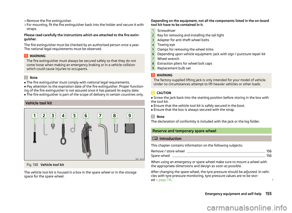
Fig. 130
Vehicle tool kit
The vehicle tool kit is housed in a box in the spare wheel or in the storage
space for the spare wheel.
Depending on the equipment, not all the components listed in the on-board
tool kit have to be contained in it.
Screwdriver
Key for removing and installing the tail light
Adapter for anti-theft wheel bolts
Towing eye
Clamps for removing the wheel trims
Depending upon vehicle equipment: Jack with sign / puncture repair kit
Wheel wrench
Extraction pliers for wheel bolt caps
Replacement bulb setWARNINGThe factory-supplied lifting jack is only intended for your model of vehicle.
Under no circumstances attempt to lift heavier vehicles or other loads.
CAUTION
■ Screw the jack back into the starting position before storing in the box with
the tool kit.■
Ensure that the vehicle tool kit is safely secured in the boot.
■
Ensure that the box is always secured with the strap.
Note
The declaration of conformity is included with the jack or the log folder.
Reserve and temporary spare wheel
Introduction
This chapter contains information on the following subjects:
Remove / store wheel
156
Spare wheel
156
When using an emergency or spare wheel make sure to mount a wheel with
the appropriate dimensions and design as soon as possible.
After changing the spare wheel, the tyre pressure should be adjusted. In vehi- cles with tyre pressure monitoring, tyre pressure values are to be stor-
ed » page 115 .
123456789155Emergency equipment and self-help
Page 159 of 200

WARNING■If, in the case of puncture occurring, the spare tyre with a non-bound di-
rection or an opposite direction of rotation must be mounted, then drive
carefully. The best properties of the tyre are no longer present in this situa-
tion.■
If the dimensions or design of the spare wheel differ from the tyres fitted
to the vehicle (e.g. winter tyres or low-profile tyres), it must only be used
briefly in the event of a puncture and if an appropriately cautious style of
driving is adopted.
■
If the dimensions or design of the temporary spare wheel differ from the
fitted tyres, never drive faster than 80 km/h (or 50 mph).
■
Never use the temporary spare wheel if it is damaged.
Remove / store wheel
Fig. 131
Taking the wheel out
Read and observe on page 156 first.
The spare wheel is located in a well under the floor covering in the boot and is
fixed in place with a special bolt » Fig. 131.
Take out the wheel
›
Open the boot lid.
›
Lift up the floor in the luggage compartment.
›
Loosen the belt and take out the box with the tool kit.
›
Unscrew the nut in direction of arrow » Fig. 131.
›
Take out the wheel.
Stow the wheel
›
Place the wheel into the spare wheel well with the wheel rim pointing down-
ward.
›
Pull the fixing band through the opposite holes in the wheel rim.
› Screw on the nut in the opposite direction to the arrow
» Fig. 131 until the
wheel is safely secured.›
Place the box with the tool kit back into the spare wheel and secure it with
the tape.
›
Fold back the floor in the luggage compartment.
›
Close the boot lid.
Spare wheel
Read and observe
on page 156 first.
A warning label is displayed on the rim of the temporary spare wheel.
Please note the following if you intend to use the temporary spare wheel. › The warning label must not be covered after installing the wheel.
› Be particularly observant when driving.
› The temporary spare wheel is inflated to the maximum inflation pressure for
the vehicle » page 149.
› Only use this temporary spare wheel to reach the nearest specialist garage,
since it is not intended for permanent use.
WARNING■ Never drive with more than one temporary spare wheel mounted!■Only use the temporary spare wheel when absolutely necessary.■
Avoid accelerating at full throttle, sharp braking and fast cornering.
■
The snow chains cannot be used on the temporary spare wheel.
■
Observe the instructions on the warning sign of the temporary spare
wheel.
Changing a wheel
Introduction
This chapter contains information on the following subjects:
Preliminary work
157
Full wheel trim
157
Wheel bolts
157
Changing a wheel
158
Follow-up work
158
Loosening/tightening wheel bolts
158
156Do-it-yourself
Page 180 of 200

Technical data
Technical data
Vehicle data
Introduction
This chapter contains information on the following subjects:
Vehicle characteristics
177
Operating weight and payload
178
Measurement of fuel consumption and CO 2 emissions according to ECE
Regulations and EU Directives
178
Dimensions
179
Angle
180
Vehicle-specific details per engine type
181
The details given in the vehicle's technical documentation always take prece-
dence over the details in the Owner's Manual.
The listed performance values were determined without performance-reduc- ing equipment, e.g. air conditioning system.
Vehicle characteristics
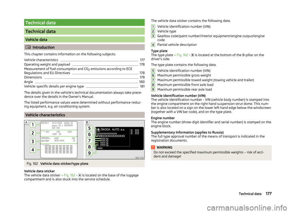
Fig. 162
Vehicle data sticker/type plate
Vehicle data sticker
The vehicle data sticker » Fig. 162 -
is located on the base of the luggage
compartment and is also stuck into the service schedule.
The vehicle data sticker contains the following data.
Vehicle identification number (VIN)
Vehicle type
Gearbox code/paint number/interior equipment/engine output/engine
code
Partial vehicle description
Type plate
The type plate » Fig. 162 -
is located at the bottom of the B-pillar on the
driver's side.
The type plate contains the following data. Vehicle identification number (VIN)
Maximum permissible gross weight
Maximum permissible towed weight (towing vehicle and trailer)
Maximum permissible front axle load
Maximum permissible rear axle load
Vehicle identification number (VIN)
The vehicle identification number - VIN (vehicle body number) is stamped into
the engine compartment on the right hand suspension strut dome. This num-
ber is also located on a sign on the lower left hand edge below the windscreen
(together with a VIN bar code), and on the type plate.
Engine number
The engine number (three-digit identifier and serial number) is stamped on the engine block.
Supplementary Information (applies to Russia)
The full type approval number of the means of transport is indicated in the
registration documents.WARNINGDo not exceed the specified maximum permissible weights – risk of acci-
dent and damage!123456789177Technical data
Page 182 of 200

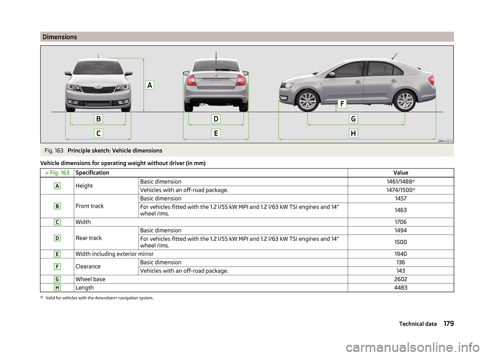
DimensionsFig. 163
Principle sketch: Vehicle dimensions
Vehicle dimensions for operating weight without driver (in mm)
» Fig. 163SpecificationValueAHeightBasic dimension1461/1488 a)Vehicles with an off-road package.1474/1500 a)B
Front track
Basic dimension1457For vehicles fitted with the 1.2 l/55 kW MPI and 1.2 l/63 kW TSI engines and 14"
wheel rims.1463CWidth1706D
Rear track
Basic dimension1494For vehicles fitted with the 1.2 l/55 kW MPI and 1.2 l/63 kW TSI engines and 14"
wheel rims.1500EWidth including exterior mirror1940FClearanceBasic dimension136Vehicles with an off-road package.143GWheel base2602HLength4483a)
Valid for vehicles with the Amundsen+ navigation system.
179Technical data
Page 196 of 200

Cavity protection131
Cleaning vehicle exterior128
Cleaning wheels131
Decorative films130
Door locking cylinder131
Headlight glasses130
Interior care132
Maintenance129
Materials133
Natural leather132
Plastic parts129
Polishing vehicle paint work129
Rubber seals129
Safety belt134
Seat covers134
Under-body protections131
washing127
Vehicle Condition see Auto Check Control
33
Vehicle data sticker177
Vehicle data sticker and nameplate Vehicle data sticker and nameplate
177
Vehicle dimensions179
Vehicle height179
Vehicle Identification Number (VIN)177
Vehicle length179
Vehicle tool kit155
Vehicle width179
Vest Placement of the reflective vest
154
VIN Vehicle Identification Number
177
Visibility64
Visors See front sun visors
65
W
Warning at excessive speeds
46
Warning triangle154
Washing Automatic car wash system128
by hand127
High-pressure cleaner128
Washing vehicles127
Waste container77
Water Driving through
107
Weather conditions124
Wheel bolts Anti-theft wheel bolts
160
Caps157
Loosening and tightening158
Wheel rims148
wheels spare wheel
156
Wheels Age of wheels
148
Changing156
Driving style149
Full trim157
General information148
Load index151
Snow chains153
Speed symbol151
Storage of wheels148
Tyre damage150
Tyre pressure149
Tyre size151
Tyre wear149
Tyre wear indicator150
Unidirectional tyres151
Wheel balance149
Wheels exchange150
Winter tyres153
Wi-Fi Password
98, 99
Settings99
Website99
Window Interior mirror67
Window wiper Replacing the rear window wiper blade
168
Windscreen washer fluid Checking
139
Replenishing139
Warning light40
Winter139
Windscreen washer system139
Windscreen wipers66
Windscreen wipers Activating
66
Replacing the windscreen wipers168
Windscreen washer fluid139
Windscreen wipers and washers65
Winter operation152
De-icing windows130
Snow chains153
Winter tyres153
Winter tyres See Wheels
153
Wiper blades132
Service position of the windscreen wiper arms 168
Wipers Maintaining wiper blades
132
193Index