traction control SKODA RAPID 2014 1.G Owner's Manual
[x] Cancel search | Manufacturer: SKODA, Model Year: 2014, Model line: RAPID, Model: SKODA RAPID 2014 1.GPages: 200, PDF Size: 25.57 MB
Page 5 of 200
Table of Contents
Board literature4
Notes
5
Structure and more information about the
Operating Instructions
6
Abbreviations
Safety
Passive Safety
8
General information
8
Correct and safe seated position
9
Seat belts
12
Using seat belts
12
Inertia reels and belt tensioners
15
Airbag system
16
Description of the airbag system
16
Airbag overview
17
Deactivating airbags
20
Transporting children safely
22
Child seat
22
Fastening systems
25
Using the system
Cockpit
29
Overview
28
Instruments and Indicator Lights
30
Instrument cluster
30
Indicator lights
34
Information system
41
Driver information system
41
Multifunction display (MFD)
43MAXI DOT display46Service interval display47
Unlocking and opening
49
Unlocking and locking
49
Anti-theft alarm system
53
Luggage compartment lid
54
Power windows
55
Mechanical windows
57
Lights and visibility
58
Lights
58
Interior lighting
63
Visibility
64
Windscreen wipers and washers
65
Rear mirror
66
Seats and head restraints
69
Seats and head restraints
69
Seat features
71
Transporting and practical equipment
73
Useful equipment
73
Luggage compartment
80
Roof rack
84
Heating and air conditioning
85
Heating, ventilation, cooling
85
Communication and multimedia
90
Universal telephone installation GSM II
90
Voice control
94
Multimedia
96
SmartGate
98
Driving
Starting-off and Driving
100
Starting and turning off the engine
100
Brakes and parking
102
Manual gear changing and pedals
103
Automatic gearbox
104Retraction and economical driving107Driving through water and driving off of
made-up roads107
Assist systems
109
Braking and stabilisation systems
109
Parking aid
110
Cruise Control System
111
START-STOP
112
Tyre pressure monitoring
115
Hitch and trailer
116
Hitch
116
Trailer
121
General Maintenance
Care and maintenance
124
Service work, adjustments and technical alterations
124
Washing vehicle
127
Cleaning vehicle exterior
128
Interior care
132
Inspecting and replenishing
134
Fuel
134
Engine compartment
137
Engine oil
140
Coolant
142
Brake fluid
143
Vehicle battery
144
Wheels
148
Tyres and wheel rims
148
Manufacturer-approved tyre variants
151
Winter operation
1522Table of Contents
Page 10 of 200
AbbreviationsAbbreviationDefinitionrpmEngine revolutions per minuteA2DPa Bluetooth software profile for a one-way transfer of audio
dataABSAnti-lock brake systemAGAutomatic gearboxAGMVehicle battery typeTCSTraction controlCO 2Carbon dioxideDPFDiesel particle filterDSGAutomatic double clutch gearboxEDLElectronic differential lockECEEconomic Commission for EuropeEPCEPC fault lightESCElectronic Stability ControlETRim depthEUEuropean UnionGSMGlobal System for Mobile communicationsHBAHydraulic brake assistHHCUphill start assistkWKilowatt, measuring unit for the engine outputMDIInputs for connecting external devicesMFDMultifunction displayMGManual gearboxMPIGasoline engine with a multi-point fuel injectionN1Panel van intended exclusively or mainly for the transporta-
tion of goodsNmNewton meter, measuring unit for the engine torquePINpersonal identification numberSIM carda card for the identification of the mobile network operatorAbbreviationDefinitionTDI CRDiesel engine with turbo charging and common rail injection
systemTSIPetrol engine with turbocharging and direct injectionVINVehicle identification numberWi-Fiwireless data network7Abbreviations
Page 37 of 200
Some error messages and other information are displayed in the MAXI DOT
display. The messages are displayed simultaneously with the icons in the MAXI
DOT display or with the warning lights in the instrument cluster » page 34,
Indicator lights .
The menu item Vehicle status is shown in the main menu of the MAXI DOT
display whenever at least one fault message exists. After selecting this menu,
the first of the error messages is displayed.
If there are several error messages, the display will show 1/3, for example, be-
low the message. This indicates that the first of a total of three error messag-
es is being displayed.
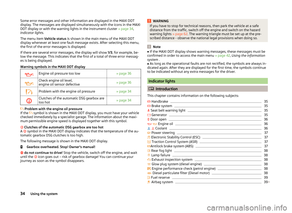
Warning symbols in the MAXI DOT displayEngine oil pressure too low» page 36Check engine oil level,
engine oil sensor defective» page 36Problem with the engine oil pressure» page 34Clutches of the automatic DSG gearbox are
too hot» page 34
Problem with the engine oil pressure
If the symbol is shown in the MAXI DOT display, you must have your vehicle
checked immediately by a specialist garage. The information about the maxi-
mum permissible engine speed is displayed together with this symbol.
Clutches of the automatic DSG gearbox are too hot
A symbol in the MAXI DOT display indicates that the temperature of the au-
tomatic gearbox DSG clutches is too high.
The following message is shown in the MAXI DOT display. Gearbox overheated. Stop! Owner's manual!
do not continue to drive! Stop the vehicle, switch off the engine, and wait
until the icon goes out – risk of gearbox damage! You can continue your
journey as soon as the symbol disappears.
WARNINGIf you have to stop for technical reasons, then park the vehicle at a safe
distance from the traffic, switch off the engine and switch on the hazard
warning lights » page 62. The warning triangle must be set up at the pre-
scribed distance - observe the national legal provisions when doing so.
Note
■ If the MAXI DOT display shows warning messages, these messages must be
confirmed in order to access the main menu » page 42, Using the information
system .■
As long as the operational faults are not rectified, the symbols are always in-
dicated again. After they are displayed for the first time, the symbols continue
to be indicated without any extra messages for the driver.
Indicator lights
Introduction
This chapter contains information on the following subjects:
Handbrake
35
Brake system
35
Seat belt warning light
35
Generator
35
Door open
36
Engine oil
36
Coolant
36
Power steering
37
Electronic Stability Control (ESC)
37
Traction Control System (ASR)
37
Antilock brake system (ABS)
37
Rear fog light
38
Lamp failure
38
Exhaust inspection system
38
Glow plug system (diesel engine)
38
Engine performance check (petrol engine)
38
Diesel particulate filter (Diesel motor)
38
Fuel reserve
39
Airbag system
39
34Using the system
Page 40 of 200
WARNING■Carefully open the coolant expansion bottle. If the engine is hot, the cool-
ing system is pressurized – risk of scalding! It is therefore best to allow the
engine to cool down before removing the cap.■
Do not touch the radiator fan. The radiator fan may switch itself on auto-
matically even if the ignition is off - a danger of injury is present!
CAUTION
■ Additional headlights and other attached components in front of the air inlet
impair the cooling efficiency of the coolant.■
Never cover the radiator - there is a risk of the engine overheating.
Power steering
Read and observe
on page 35 first.
If the indicator light
is illuminated , there is a fault in the power steering sys-
tem.
The power steering operates with reduced steering assist or does not function
at all.
Seek assistance from a specialist garage immediately.
Electronic Stability Control (ESC)
Read and observe
on page 35 first.
The warning light
flashes to show that the ESC is currently operating.
If the warning light
illuminates , there is a fault in the ESC.
The following message is shown in the MAXI DOT display. Error: stabilization control (ESC)
or Error: Traction control (TCS)
Seek assistance from a specialist garage immediately.
If the warning light
illuminates immediately after you start the engine, the
ESC might be switched off due to technical reasons.
›
Switch the ignition off and on again.
If the warning light does not illuminate after you switch the engine back on,
the ESR is fully functional again.
Further information » page 109, Electronic Stability Control (ESC) .
Note
If the vehicle battery has been disconnected and then reconnected, the warn-
ing light comes on after switching on the ignition. If the warning light does
not go out after moving a short distance, this means that there is an error in
the system. Seek assistance from a specialist garage immediately.
Traction Control System (ASR)
Read and observe
on page 35 first.
The warning light flashes
to show that the ASR is currently operating.
If the warning light
illuminates , there is a fault in the ASR.
The following message is shown in the MAXI DOT display. Error: Traction control (TCS)
Seek assistance from a specialist garage immediately.
If the warning light
illuminates immediately after you start the engine, the
ASR might be switched off due to technical reasons.
›
Switch the ignition off and on again.
The ASR is fully functional again if the warning light
no longer illuminates
after you switch the engine back on.
Further information » page 109, Traction Control System (TCS) .
Note
If the vehicle battery has been disconnected and then reconnected, the warn-
ing light comes on after switching on the ignition. If the warning light does
not go out after moving a short distance, this means that there is an error in
the system. Seek assistance from a specialist garage immediately.
Antilock brake system (ABS)
Read and observe
on page 35 first.
If the warning light
illuminates , there is a fault in the ABS.
37Instruments and Indicator Lights
Page 95 of 200
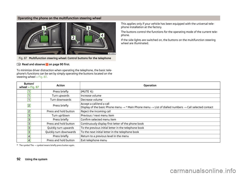
Operating the phone on the multifunction steering wheelFig. 87
Multifunction steering wheel: Control buttons for the telephone
Read and observe
on page 90 first.
To minimize driver distraction when operating the telephone, the basic tele-
phone's functions can be set by simply operating the buttons located on the
steering wheel » Fig. 87.
This applies only if your vehicle has been equipped with the universal tele-
phone installation at the factory.
The buttons control the functions for the operating mode of the current tele-
phone.
If the side lights are switched on, the buttons on the multifunction steering
wheel are illuminated.Button/
wheel » Fig. 87ActionOperation1Press briefly(MUTE )1Turn upwardsIncrease volume1Turn downwardsDecrease volume2Press brieflyAccept a call/end a call
Display of the basic Phone menu → a)
Main Phone menu → List of dialled numbers → Call selected contact2Press and hold buttonReject the incoming call3Turn up/downPrevious / next menu item3Press brieflyConfirm selected menu item3Press and hold buttonContinuously display first letter of the phone book3Quickly turn upwardsTo the previous initial letter in the telephone book3Quickly turn downwardsTo the next initial letter in the telephone book4Press brieflyReturn to a previous level in the menu4Press and hold buttonExit telephone menua)
The symbol The → symbol means briefly press button again.
92Using the system
Page 112 of 200

Assist systems
Braking and stabilisation systems
Introduction
This chapter contains information on the following subjects:
Electronic Stability Control (ESC)
109
Antilock Braking System (ABS)
109
Traction Control System (TCS)
109
Electronic Differential Lock (EDL)
110
Hydraulic Brake Assist (HBA)
110
Hill Hold Control (HHC)
110
This chapter deals with the functions of the braking and stabilisation systems,
with the error indicator referred to in chapter » page 34, Indicator lights .
The braking and stabilisation systems are automatically activated each time
the ignition is switched on.
WARNING■ A lack of fuel can cause irregular engine running or cause the engine to
shut down. The brake assist systems would then fail to function – risk of
accident!■
The increased safety provided by the brake assist systems must not
tempt you to take safety risks – risk of accident!
■
Adjust the speed and driving style to the current visibility, weather, road
and traffic conditions.
Electronic Stability Control (ESC)
Fig. 97
Press the ESC system: Activat-
ing/deactivating TCS
Read and observe on page 109 first.
The ESC improves vehicle stability in dynamic driving situations, such as when the vehicle starts to skid.
The ESC monitors whether the desired direction of the current vehicle motion
is occurring. In case of any deviation (e.g. oversteer), the ESC automatically
brakes individual wheels to maintain the desired direction.
During an intervention of the system, the warning light
flashes in the instru-
ment cluster.
The ESC system cannot be deactivated. The
» Fig. 97 button can only be
used to deactivate the TCS » page 109.
The warning light lights up in the instrument cluster when the ASR is deacti-
vated.
The TCS should normally always be enabled. The system should be deactivated
only in the following situations, for example.
› When driving with snow chains.
› When driving in deep snow or on a very loose surface.
› When “rocking a car free” when it has become stuck.
Antilock Braking System (ABS)
Read and observe
on page 109 first.
ABS prevents the wheels locking when braking. Thus helping the driver to
maintain control of the vehicle.
The intervention of the ABS is noticeable from the pulsating movements of
the brake pedal which is accompanied by noises.
When the ABS system is active, do not brake periodically or reduce the pres-
sure on the brake pedal.
Traction Control System (TCS)
Read and observe
on page 109 first.
TCS prevents the spinning of the wheels of the driven axle. TCS reduces thedrive power transmitted to the wheels in the case of slipping wheels. Thus, for
example, driving on road surfaces with low grip is made easier.
If your vehicle is fitted with the ESC system, the ASR is integrated into the ESC
system » page 109 .
109Assist systems
Page 113 of 200
NoteFor vehicles without stabilization control (ESC), during a TCS intervention the
control indicator in the instrument cluster flashes.
Electronic Differential Lock (EDL)
Read and observe
on page 109 first.
EDL prevents the turning of the respective wheel of the driven axle. EDL
brakes the spinning wheel, if necessary, and transmits the driving force to the
other driving wheel. Driving becomes easier on road surfaces with different
traction under each wheel of the driven axle.
The EDL switches off automatically in order to avoid excessive heat generation
on the brake of the wheel being braked. The vehicle can continue to be driven
and has the same characteristics as a vehicle not fitted with EDL. Once the
brakes have cooled down, there is an automatic re-activation of EDL.
Hydraulic Brake Assist (HBA)
Read and observe
on page 109 first.
The HBA increases the braking effect and helps to reduce the braking dis-
tance.
The HBA is activated by the very quick operation of the brake pedal. In order to
achieve the shortest possible braking distance, the brake pedal must be ap-
plied firmly until the vehicle has come to a standstill.
The HBA function is automatically deactivated when the brake pedal is re-
leased.
Hill Hold Control (HHC)
Read and observe
on page 109 first.
When driving on slopes, HHC allows you to move your foot from the brake ped-al to the accelerator pedal without having to use the handbrake.
The system holds the brake pressure produced by the activation of the brake pedal for approx. 2 seconds after the brake pedal is released.
The brake pressure drops gradually the more you operate the accelerator ped-
al. If the vehicle does not start off within 2 seconds, it starts to roll back.
The HHC is active from a 5% slope if the driver's door is closed. HHC is only ev-
er active on slopes when in forward or reverse start off.
Parking aid
Introduction
This chapter contains information on the following subjects:
Function
111
Activation/deactivation
111
The parking aid (hereinafter referred to only as a system) draws attention via
acoustic signals and an indication in the radio or navigation display when ma-
noeuvring around obstacles in the vicinity of the vehicle.
The system uses ultrasound waves to calculate the distance between the
bumper and an obstacle. The ultrasonic sensors are integrated in the rear
bumper » Fig. 98 on page 111 .
WARNING■
The system only serves to support and does not relieve the driver of the
responsibility for the vehicle operation.■
Moving persons or objects may not be recognized by the system sensors.
■
Under certain circumstances, surfaces of certain objects and types of
clothing cannot reflect the system signals. For this reason, such people or
objects may not be recognised by the system sensors.
■
External noise sources may affect the signals of the system sensors. Un-
der adverse conditions, this may cause objects or people not to be recog-
nised by the system.
■
Before reversing, you should make sure that there are no small obstacles,
such as rocks, thin posts, trailer drawbars etc. behind your vehicle. Such ob-
stacles may not be recognised by the system sensors.
CAUTION
■ Keep the system sensors clean, snow-and ice-free and do not cover with any
objects of any kind, otherwise the system functioning may be impaired.■
Under adverse weather conditions (heavy rain, water vapour, very low or
high temperatures etc.), the system function may be limited - “incorrect recog-
nition of obstacle”.
■
Additionally installed accessories such as e.g. bicycle carriers can impair the
system function.
110Driving
Page 194 of 200
Refuelling135
Fuel135
Remote control Locking
50
Replacing the battery166
Synchronisation process166
Unlocking50
Remote control key Replacing the battery
166
Removing the bar ball, Step 1
119
bar ball, Step 2119
Repairs and technical alterations124
Replacing Bulb for main beam, daytime running lights andparking light
173
Bulb for the fog light174
Bulb for the licence plate light175
Bulb in rear light176
Fuses169
Fuses in the dash panel169
Fuses in the engine compartment171
High beam bulb (halogen headlights)173
Rear window wiper blade168
Vehicle battery147
windscreen wiper blades168
Replenishing Coolant
143
Engine oil142
Windscreen washer fluid139
Retraction and economical driving107
Revolution counter31
Roof Load
85
Roof rack84
mounting points85
Roof load85
Rubber seals129
S
SAFE See Safe securing system
51
SAFELOCK See Safe securing system
51
Safe securing system51
Safety8
Child safety22
Child safety seats22
Correct seated position9
Head restraints70
ISOFIX25
TOP TETHER26
Save electrical energy107
Save fuel107
Seals Vehicle care
129
Seat Adjusting
69
Seat belt warning light
35
Seat belts12
Belt tensioners15
fastening and unfastening14
Height adjustment15
Inertia reels15
The physical principle of a frontal collision13
Seat features71
Seats Front armrest
72
Head restraints70
Heating71
Rear armrest72
Seat backrests72
Seats and head restraint69
Selector lever Refer to Selector lever
105
Service125
Service interval display47
Setting33
seats and head restraints69
Setting the33
Side airbag18
SmartGate connection
98
Password99
Settings99
Smart Gate Website
99
Snow chains153
Spare change
156
spare wheel155
change156
instructions156
Speedometer31
See speedometer31
Speed symbol See Wheels
151
Spoiler126
Staring engine Jump-starting
163
START-STOP112
Jump-starting163
Manually deactivating/activating the system114
Operating conditions of the system113
operation in vehicles with automatic gearbox113
operation in vehicles with manual gearbox113
system-related automatic start-up114
Start engine101
Starting engine Jump-starting
162
START STOP Information messages
114
Stating and turning off the engine100
Steering wheel10
Stopping103
Storage73
191Index
Page 195 of 200
Storage compartmentGlasses compartment78
in the boot83
in the centre console74
in the front arm rest78
on the front passenger side78
Storage compartments73
Storage pockets on the front seats79
Stowage compartments in the doors
74
Sun visors65
Switching off the engine101
Switch light on/off58
Switch off ignition101
Switch on ignition101
T
Taking care of your vehicle Automatic car wash system
128
High-pressure cleaner128
Washing by hand127
Wash system128
TCS Operation
109
Technical data177
Telephone90
Tiptronic106
Tools155
TOP TETHER26
Towing164
Towing a trailer122
Towing device Description
116
Operation and maintenance131
Towing eye Front
165
Rear165
Towing protection54
Traction Control System (TCS)109
Trailer121
13-pin socket121
connection and disconnection121
Loading122
Safety eye121
Towing a trailer122
Trailer operation116
Transport Luggage compartment
80
Roof rack84
Transporting73
Transporting children safely22
Triangle154
Turn signal60
Turn signal system Warning light
40
two-way radio systems90
Tyre Damage
150
Explanation of the labelling151
see wheels151
Tyre inflation pressure Warning light
40
Tyre load-bearing capacity See Wheels
151
Tyre pressure149
Tyre pressure monitoring115
Save tyre pressure values115
Tyre repair General notes
161
Preparations161
Pressure test162
Sealing and inflating the tyre162
Tyres148
new107
Tyre pressure149
Wear and tear149
Wear indicators150
Tyre size151
see wheels151
U
Under-body Vehicle care
131
Under-body protection131
Unlock Key
50
Unlocking Individual settings
52
Remote control50
Unlocking and locking49
USB97
Used vehicles Acceptance and recycling
127
Useful equipment Ashtray
76
Car park ticket holder74
Cigarette lighter75
Clothes hook79
Cup holders74
Glasses compartment78
Multimedia holder77
Storage compartment73
Using the information system42
Using the selector lever105
V
Vehicle battery Automatic load deactivation
147
charging146
Checking the battery electrolyte level146
Cover145
Operation in winter146
Replacing147
Safety instructions144
vehicle care chrome parts
129
Vehicle care Alcantara
133
Artificial leather133
192Index