towing SKODA RAPID 2015 1.G User Guide
[x] Cancel search | Manufacturer: SKODA, Model Year: 2015, Model line: RAPID, Model: SKODA RAPID 2015 1.GPages: 204, PDF Size: 27.52 MB
Page 122 of 204
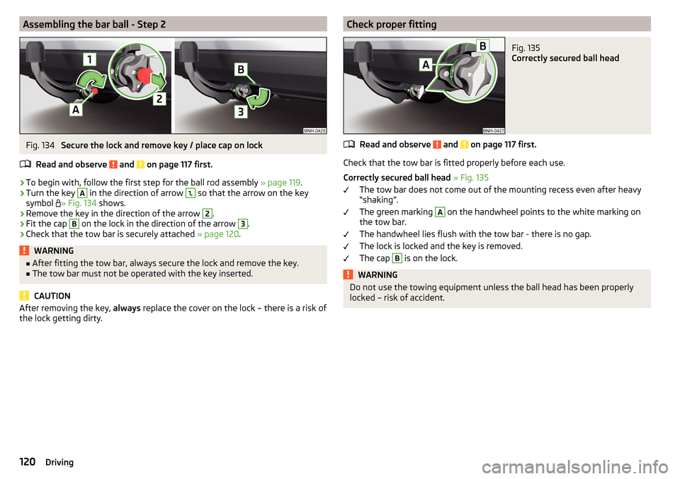
Assembling the bar ball - Step 2Fig. 134
Secure the lock and remove key / place cap on lock
Read and observe
and on page 117 first.
›
To begin with, follow the first step for the ball rod assembly » page 119.
›
Turn the key
A
in the direction of arrow
1,
so that the arrow on the key
symbol » Fig. 134
shows.
›
Remove the key in the direction of the arrow
2
.
›
Fit the cap
B
on the lock in the direction of the arrow
3
.
›
Check that the tow bar is securely attached » page 120.
WARNING■
After fitting the tow bar, always secure the lock and remove the key.■The tow bar must not be operated with the key inserted.
CAUTION
After removing the key, always replace the cover on the lock – there is a risk of
the lock getting dirty.Check proper fittingFig. 135
Correctly secured ball head
Read and observe and on page 117 first.
Check that the tow bar is fitted properly before each use.
Correctly secured ball head » Fig. 135
The tow bar does not come out of the mounting recess even after heavy
“shaking”.
The green marking
A
on the handwheel points to the white marking on
the tow bar.
The handwheel lies flush with the tow bar - there is no gap.
The lock is locked and the key is removed.
The cap
B
is on the lock.
WARNINGDo not use the towing equipment unless the ball head has been properly
locked – risk of accident.120Driving
Page 124 of 204

CAUTION■If the hand wheel A is not turned all the way to the stop, then it will return
to its initial position when the tow bar is removed and will rest on the tow bar
and not engage into the ready position. The ball head then needs to be
brought into this position before the next time it is fitted » page 118, Adjusting
the ready position .■
The mounting recess must be closed with the cover following removal. This
prevents foreign bodies from getting into the mounting recess.
Note
Clean any dirt from the tow bar before stowing it away in the box with the ve-
hicle tool kit.
Mount accessories
Fig. 139
Representation of the maximum
permissible level of the ball head
of the towing hitch and the per-
missible total weight of the ac-
cessories including the load de-
pending on the load centre of
gravity
Read and observe and on page 117 first.
An accessory can mounted on the ball head of the towing hitch (e.g. bike carri- ers).
If this accessory is used, the maximum permissible overhang of the ball head
of the towing hitch and the permissible gross vehicle weight of the accesso-
ries including load are to be checked.
The maximum permissible overhang of the ball head of the towing hitch is 70
cm » Fig. 139 .
The total permitted weight of the accessory including load changes with in-
creasing distance of the centre of gravity of the load from the ball head of the
towing hitch.
Distance of the centre of gravity of the load from the ball headPermissible total weight of the ac- cessory, including load0 cm50 kg30 cm50 kg60 cm25 kg70 cm0 kgWARNING■Never exceed the permissible gross weight of the accessory including
load - there is a risk of damaging the towing device.■
Never exceed the permissible protrusion of the ball head including towing
device - there is a risk of damaging the towing device.
Note
We recommend that you use accessories from ŠKODA Original Accessories.
Trailer
Introduction
This chapter contains information on the following subjects:
Attaching and detaching trailers
123
Loading a trailer
123
Trailer load
124
Towing a trailer
124
Anti-theft alarm system
124
The trailer can be hitched to the ball head of the towing device.
122Driving
Page 125 of 204
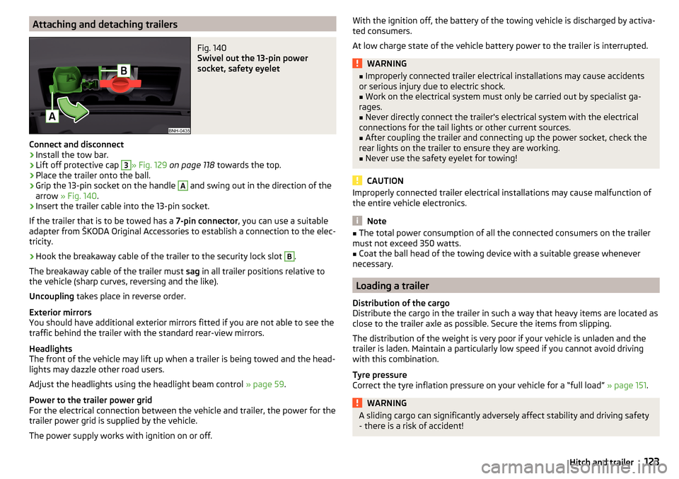
Attaching and detaching trailersFig. 140
Swivel out the 13-pin power
socket, safety eyelet
Connect and disconnect
›
Install the tow bar.
›
Lift off protective cap
3
» Fig. 129 on page 118 towards the top.
›
Place the trailer onto the ball.
›
Grip the 13-pin socket on the handle
A
and swing out in the direction of the
arrow » Fig. 140 .
›
Insert the trailer cable into the 13-pin socket.
If the trailer that is to be towed has a 7-pin connector, you can use a suitable
adapter from ŠKODA Original Accessories to establish a connection to the elec-
tricity.
›
Hook the breakaway cable of the trailer to the security lock slot
B
.
The breakaway cable of the trailer must sag in all trailer positions relative to
the vehicle (sharp curves, reversing and the like).
Uncoupling takes place in reverse order.
Exterior mirrors
You should have additional exterior mirrors fitted if you are not able to see the
traffic behind the trailer with the standard rear-view mirrors.
Headlights
The front of the vehicle may lift up when a trailer is being towed and the head-
lights may dazzle other road users.
Adjust the headlights using the headlight beam control » page 59.
Power to the trailer power grid
For the electrical connection between the vehicle and trailer, the power for the
trailer power grid is supplied by the vehicle.
The power supply works with ignition on or off.
With the ignition off, the battery of the towing vehicle is discharged by activa- ted consumers.
At low charge state of the vehicle battery power to the trailer is interrupted.WARNING■ Improperly connected trailer electrical installations may cause accidents
or serious injury due to electric shock.■
Work on the electrical system must only be carried out by specialist ga-
rages.
■
Never directly connect the trailer's electrical system with the electrical
connections for the tail lights or other current sources.
■
After coupling the trailer and connecting up the power socket, check the
rear lights on the trailer to ensure they are working.
■
Never use the safety eyelet for towing!
CAUTION
Improperly connected trailer electrical installations may cause malfunction of
the entire vehicle electronics.
Note
■ The total power consumption of all the connected consumers on the trailer
must not exceed 350 watts.■
Coat the ball head of the towing device with a suitable grease whenever
necessary.
Loading a trailer
Distribution of the cargo
Distribute the cargo in the trailer in such a way that heavy items are located as
close to the trailer axle as possible. Secure the items from slipping.
The distribution of the weight is very poor if your vehicle is unladen and the
trailer is laden. Maintain a particularly low speed if you cannot avoid driving
with this combination.
Tyre pressure
Correct the tyre inflation pressure on your vehicle for a “full load” » page 151.
WARNINGA sliding cargo can significantly adversely affect stability and driving safety
- there is a risk of accident!123Hitch and trailer
Page 126 of 204
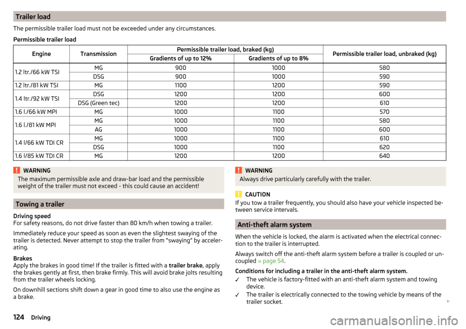
Trailer loadThe permissible trailer load must not be exceeded under any circumstances.Permissible trailer loadEngineTransmissionPermissible trailer load, braked (kg)Permissible trailer load, unbraked (kg)Gradients of up to 12%Gradients of up to 8%1.2 ltr./66 kW TSIMG9001000580DSG90010005901.2 ltr./81 kW TSIMG110012005901.4 ltr./92 kW TSIDSG12001200600DSG (Green tec)120012006101.6 l./66 kW MPIMG100011005701.6 l./81 kW MPIMG10001100580AG100011006001.4 l/66 kW TDI CRMG10001100610DSG100011006201.6 l/85 kW TDI CRMG12001200640WARNINGThe maximum permissible axle and draw-bar load and the permissible
weight of the trailer must not exceed - this could cause an accident!
Towing a trailer
Driving speed
For safety reasons, do not drive faster than 80 km/h when towing a trailer.
Immediately reduce your speed as soon as even the slightest swaying of the
trailer is detected. Never attempt to stop the trailer from “swaying” by acceler-
ating.
Brakes
Apply the brakes in good time! If the trailer is fitted with a trailer brake, apply
the brakes gently at first, then brake firmly. This will avoid brake jolts resulting
from the trailer wheels locking.
On downhill sections shift down a gear in good time to also use the engine as
a brake.
WARNINGAlways drive particularly carefully with the trailer.
CAUTION
If you tow a trailer frequently, you should also have your vehicle inspected be-
tween service intervals.
Anti-theft alarm system
When the vehicle is locked, the alarm is activated when the electrical connec-
tion to the trailer is interrupted.
Always switch off the anti-theft alarm system before a trailer is coupled or un-
coupled » page 54 .
Conditions for including a trailer in the anti-theft alarm system. The vehicle is factory-fitted with an anti-theft alarm system and towing
device.
The trailer is electrically connected to the towing vehicle by means of the
trailer socket.
124Driving
Page 132 of 204
Automatic car wash systemsRead and observe
and on page 129 first.
The usual precautionary measures must be taken before washing the vehicle
in an automatic car wash system (e.g. closing the windows and the sliding/tilt-
ing roof etc.).
If your vehicle is fitted with any particular attached parts, such as a spoiler,
roof rack system etc., it is best to consult the operator of the car wash system
beforehand.
After an automatic wash with wax treatment, the lips of the wipers should be
cleaned with cleaning agents specially designed for the purpose, and then de-
greased.
CAUTION
■ Before driving through a car wash fold in the exterior mirrors - there is a risk
of damage.■
Before driving through a car wash unscrew the antenna - there is a risk of
damage.
Washing with a high-pressure cleaner
Read and observe
and on page 129 first.
When washing the vehicle with a high-pressure cleaner, the instructions foruse of the equipment must be observed. This applies in particular to the pres-
sure used and to the spraying distance .
Maintain a sufficiently large distance to the parking aid sensors and soft mate-
rials such as rubber hoses or insulation material.
CAUTION
■ The films should not be washed with any high-pressure cleaners - there is a
risk of damage » page 131.■
Do not aim the water jet directly at the lock cylinders or the door or opening
joints when washing the vehicle in the winter – there is a risk of freezing.
■
The sensors of the parking aid can be sprayed only for a short time and there
must be a minimum distance of 10 cm - there is a risk of damage.
Cleaning vehicle exterior
Introduction
This chapter contains information on the following subjects:
Vehicle paint work
131
Films
131
Plastic parts
131
Rubber seals
132
Chrome and anodized parts
132
Windows and external mirrors
132
Headlight glasses
132
Door closing cylinder
133
Cavity protection
133
Jack
133
Wheels
133
Towing device and mounting recess
133
Under-body protection
134
Wiper blades
134
We recommend using vehicle care products from ŠKODA Original Accessories.
These are available from ŠKODA Partners. The usage instructions on the pack-
age must be observed.
WARNING■ Vehicle care products may be harmful to your health if not used according
to the instructions.■
Always keep the vehicle care products safe from people who are not com-
pletely independent, e.g. children - there is a danger of poisoning!
■
Protect your hands and arms from sharp-edged metal parts when clean-
ing the underfloor, the inside of the wheel housings or the wheel trims –
risk of cuts!
CAUTION
■ Do not use any insect sponges, rough kitchen sponges or similar cleaning
products – risk of damaging the paintwork surface.■
Cleaners containing solvents can damage the material being cleaned.
130General Maintenance
Page 135 of 204
CAUTION■The headlights are never to be wiped dry - there is a risk of damaging the
protective lacquer and the headlight glass subsequently developing cracks.■
Do not use sharp objects to clean the glasses - there is a risk of damaging
the protective lacquer and the headlight glasses subsequently developing
cracks.
■
Do not use any aggressive cleaning or chemical solvent products to clean the
headlights – risk of damaging the headlight lenses.
Door closing cylinder
Read and observe
and on page 130 first.
Specific products must be used for de-icing door lock cylinders.
CAUTION
Make sure that as little water as possible gets into the locking cylinder when
washing the vehicle - there is a risk of freezing the lock cylinder!
Cavity protection
Read and observe
and on page 130 first.
All the cavities of your vehicle which are at risk from corrosion are protectedfor life by a layer of protective wax applied in the factory.
This wax protection does not need to be inspected or re-applied.
If any small amount of wax flow out of the cavities at high temperatures, these
must be removed with a plastic scraper and the stains cleaned using a petrole-
um cleaner.
WARNINGSafety regulations should be observed when using petroleum cleaner to re-
move wax – risk of fire!
Jack
Read and observe
and on page 130 first.
The jack is maintenance-free.
If necessary, the moving parts of the jack should be lubricated with a suitable lubricant.
Wheels
Read and observe
and on page 130 first.
Wheel rims
Also thoroughly wash the wheel rims when washing the vehicle on a regular basis.
Regularly remove salt and brake abrasion, otherwise the rim material will be
corroded.
Light alloy wheels
After washing thoroughly, treat the wheel rims with a protective product for
light alloy wheels.
For the treatment of wheel rims do not use products which may cause damage
to the paint on the rims.
CAUTION
■ Damage to the paint layer on the wheel rims must be touched up immediate-
ly.■
Severe layers of dirt on the wheels can also result in wheel imbalance. This
may show itself in the form of a wheel vibration which is transmitted to the
steering wheel which, in certain circumstances, can cause premature wear of
the steering. This means it is necessary to remove the dirt.
Towing device and mounting recess
Read and observe
and on page 130 first.
Close the mounting recess with the cover to prevent any dirt from getting in.
If dirt is present, clean the inner surfaces of the mounting recess and treat
with a suitable preservative.
Always check the ball head before hitching a trailer. Apply a suitable grease, if
necessary.
Use the protective cover when stowing away the tow bar, in order to stop the
boot from getting dirty.
CAUTION
Apply grease to the inner part of the mounting recess. Make sure you do not
remove any grease.133Care and maintenance
Page 159 of 204
Removing/attaching›Loosen the two straps by pulling the buckles in the direction of the arrow
» Fig. 155 .›
Remove the fire extinguisher.
›
For mounting, fit the fire extinguisher back into the holder and secure it with
straps.
Please read the instructions which are attached to the fire extinguisher.
Pay attention to the expiration date of the fire extinguisher. Proper function-
ing of the fire extinguisher is not assured once it has passed its expiry date.
WARNINGThe fire extinguisher must always be secured safely so that they do not
come loose when making an emergency braking or in a vehicle collision
which could cause injuries to occupants.
Note
The fire extinguisher is part of the scope of delivery in certain countries only.
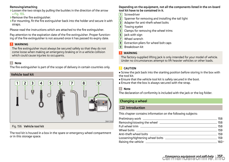
Vehicle tool kit
Fig. 156
Vehicle tool kit
The tool kit is housed in a box in the spare or emergency wheel compartment
or in this storage space.
Depending on the equipment, not all the components listed in the on-board
tool kit have to be contained in it.
Screwdriver
Spanner for removing and installing the tail light
Adapter for anti-theft wheel bolts
Towing eyelet
Clamps for removing the wheel trims
Jack with sign
Wheel wrench
Extraction pliers for wheel bolt caps
Breakdown kitWARNINGThe factory-supplied lifting jack is only intended for your model of vehicle.
Under no circumstances attempt to lift heavier vehicles or other loads.
CAUTION
■ Screw the jack back into the starting position before storing in the box with
the tool kit.■
Ensure that the vehicle tool kit is safely secured in the boot.
■
Ensure that the box is always secured with the strap.
Note
The declaration of conformity is included with the jack or the log folder.
Changing a wheel
Introduction
This chapter contains information on the following subjects:
Preliminary work
158
Removing/stowing the wheel
158
Full wheel trim
158
Wheel bolts
159
Anti-theft wheel bolts
159
Loosening/tightening wheel bolts
159
Raising the vehicle
160
123456789157Emergency equipment and self-help
Page 160 of 204
Remove the wheel / fix161Follow-up work161
For your own safety and the safety of the passengers, the following instruc-
tions must be observed before changing a wheel on the road.
Switch on the hazard warning lights system.
Place the warning triangle at the prescribed distance.
Park the vehicle as far away as possible from the flowing traffic.
Choose a location with a flat, solid surface.
Have all the occupants get out. The passengers should not stand on the
road (instead they should remain behind a crash barrier, for instance) while
the wheel is being changed.
Preliminary work
Before changing the wheel, the following work must be carried out.
›
Switch off the engine.
›
For vehicles with manual transmission select 1st gear.
›
On vehicles with automatic transmission , place the selector lever in the P
position.
›
Firmly apply the handbrake.
›
Uncouple trailer, if attached.
Removing/stowing the wheel
Fig. 157
Take out the wheel
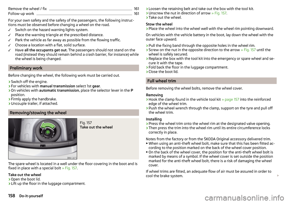
The spare wheel is located in a well under the floor covering in the boot and is
fixed in place with a special bolt » Fig. 157.
Take out the wheel
›
Open the boot lid.
›
Lift up the floor in the luggage compartment.
› Loosen the retaining belt and take out the box with the tool kit.›Unscrew the nut in direction of arrow
» Fig. 157.›
Take out the wheel.
Stow the wheel
›
Place the wheel into the wheel well with the wheel rim pointing downward.
On vehicles with the vehicle battery in the boot, lay down the wheel with the
outer face upward.
›
Pull the fixing band through the opposite holes in the wheel rim.
›
Screw on the nut in the opposite direction to the arrow » Fig. 157 until the
wheel is safely secured.
›
Replace the box with the tool kit into the emergency or spare wheel and se-
cure it with the tape.
›
Fold back the floor in the luggage compartment.
›
Close the boot lid.
Full wheel trim
Before removing the wheel bolts, remove the wheel cover.
Removing
›
Hook the clamp found in the vehicle tool kit » page 157 into the reinforced
edge of the wheel trim.
›
Push the wheel wrench through the clamp, support on the tyre and pull off
the wheel trim.
Installing
›
Press the wheel trim onto the wheel rim at the designated valve opening.
›
Then press the trim into the wheel rim until its entire circumference locks
correctly in place.
Notes from the factory or from the ŠKODA Original accessory delivered trim.
▶ When using an anti-theft wheel bolt, make sure that this has been fitted ac-
cording to the position marked on the back of the wheel cover position.
▶ On the back of the wheel cover, the position for the anti-theft wheel bolt is
marked by means of a symbol. If the wheel cover is set outside the position
marked for the anti-theft wheel bolt, there is a risk of damaging the wheel
cover.
If wheel trims are fitted, an adequate flow of air must be assured in order to
cool the brake system.
158Do-it-yourself
Page 167 of 204
The jump-start cable must be connected to the engine earthing point C» Fig. 164 only on vehicles with the START-STOP system.
Starting engine›
Start the engine on the vehicle providing the power and allow it to idle.
›
Start the engine of the vehicle with the discharged battery.
›
If the engine does not start, halt the attempt to start the engine after 10 sec-
onds and wait for 30 seconds before repeating the process.
›
Remove the jump start cables in the reverse order as attachment.
Engines in vehicles with the vehicle battery in the boot
The positive terminal
A
is located under a cover in the engine compartment
» Fig. 165 .
›
Unlock the retainer tab on the cover in direction of arrow
1
.
›
Open the cover in the direction of the arrow
2
.
›
Clamp the positive terminal of the jumper cable to the position
A
» Fig. 165 .
›
Clamp the negative terminal of the jumper cable to the earthing point of the
engine
D
» Fig. 164 or on a metal part firmly connected to the engine block
or directly on the engine block.
›
Remove the jump start cables in the reverse order as attachment.
Both batteries must have a rated voltage of 12 V. The capacity (Ah) of the bat-
tery supplying the power must not be significantly less than the capacity of
the discharged battery in your vehicle.
Jump-start cables
Only use jump-start cables which have an adequately large cross-section and
insulated terminal clamps. Observe the instructions of the jumper lead manu-
facturer.
Positive cable – colour coding in the majority of cases is red.
Negative cable – colour coding in the majority of cases is black.
WARNING■
Do not clamp the jump-start cable to the negative terminal of the dis-
charged battery. There is the risk of detonating gas seeping out the battery
being ignited by the strong spark which results from the engine being star-
ted.■
The non-insulated parts of the terminal clamps must never touch each
other – there is a risk of short circuit.
WARNING (Continued)■ The jump-start cable connected to the positive terminal of the battery
must not come into contact with electrically conducting parts of the vehicle
– there is a risk of short circuit.■
Route the jump-start cables so that they cannot be caught by any rotat-
ing parts in the engine compartment.
Towing the vehicle
Introduction
Fig. 166
Braided tow rope / Spiral tow rope
This chapter contains information on the following subjects:
Front towing eye
166
Rear towing eye
167
Vehicles with a tow hitch
167
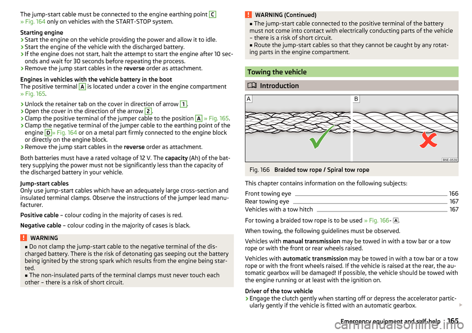
For towing a braided tow rope is to be used » Fig. 166-
.
When towing, the following guidelines must be observed.
Vehicles with manual transmission may be towed in with a tow bar or a tow
rope or with the front or rear wheels raised.
Vehicles with automatic transmission may be towed in with a tow bar or a tow
rope or with the front wheels raised. If the vehicle is raised at the rear, the au-
tomatic gearbox will be damaged! If possible, the vehicle should be towed with
the engine running or at least with the ignition on.
Driver of the tow vehicle
›
Engage the clutch gently when starting off or depress the accelerator partic-
ularly gently if the vehicle is fitted with an automatic gearbox.
165Emergency equipment and self-help
Page 168 of 204

›Only then approach correctly when the rope is taut.
The maximum towing speed is 50 km/h.
Driver of the towed vehicle›
Switch on the ignition so that the steering wheel is not locked and so that
the turn signal lights, windscreen wipers and windscreen washer system can
be used.
›
Take the vehicle out of gear or move the selector lever into position N if the
vehicle is fitted with an automatic gearbox.
Please note that the brake servo unit and power steering only operate if the
engine is running. If the engine is not running, significantly more physical force
is required to depress the brake pedal and steer the vehicle.
If using a tow rope, ensure that it is always kept taught.
General information for the towing process
Both drivers should be familiar with the problems which might possibly occur while a vehicle is being towed. Unskilled drivers should not attempt to tow an-
other vehicle or to be towed.
The vehicle must be transported on a special breakdown vehicle or trailer if it
is not possible to tow the vehicle in the way described or if the towing dis-
tance is greater than 50 km.
If the gearbox no longer contains any oil, your vehicle must only be towed with
the front axle raised clear of the ground or on a breakdown vehicle or trailer.
To protect both vehicles when tow-starting or towing, the tow rope should be
elastic. Thus only plastic fibre rope or a rope made out of a similarly elastic ma-
terial should be used.
Attach the tow rope or the tow bar to the towing eyes » page 166 or
» page 167 to the detachable ball head of the towing equipment » page 117 .
WARNING■
When towing, exercise increased caution.■For towing no spiral tow rope is to be used » Fig. 166- , the towing eye
may unscrew out of the vehicle - there is a risk of accidents.■
The tow rope should not be twisted - there is a risk of accidents.
CAUTION■ Do not start engine by towing - there is a risk of damaging the engine parts.
The battery from another vehicle can be used as a jump-start aid » page 164,
Jump-starting .■
There is always a risk of excessive stresses and damage resulting at the
points to which you attach the tow rope or tow bar when you attempt to tow a
vehicle which is not standing on a paved road.
Note
We recommend using a tow rope from ŠKODA Original Accessories, which is
available from a ŠKODA Partner.
Front towing eye
Fig. 167
Removing the cap/installing the towing eye
Read and observe
and on page 166 first.
Removing/installing the cap
›
Press on the cap in the direction of the arrow
1
» Fig. 167 .
›
Remove the cap in the direction of the arrow
2
.
›
After unscrewing the cap of the towing eye, insert the cap in the region of
the arrow
1
and then press the opposite side of the cap.
The cap must engage firmly.
Removing/installing the towing eye
›
Manually screw the towing eye as far as it will go in the direction of the ar-
row
3
» Fig. 167 » .
For tightening purposes, we recommend, for example, using the wheel
wrench, towing eye from another vehicle or a similar object that can be pushed through the eye.
166Do-it-yourself