stop start SKODA RAPID 2016 1.G User Guide
[x] Cancel search | Manufacturer: SKODA, Model Year: 2016, Model line: RAPID, Model: SKODA RAPID 2016 1.GPages: 184, PDF Size: 27.06 MB
Page 86 of 184
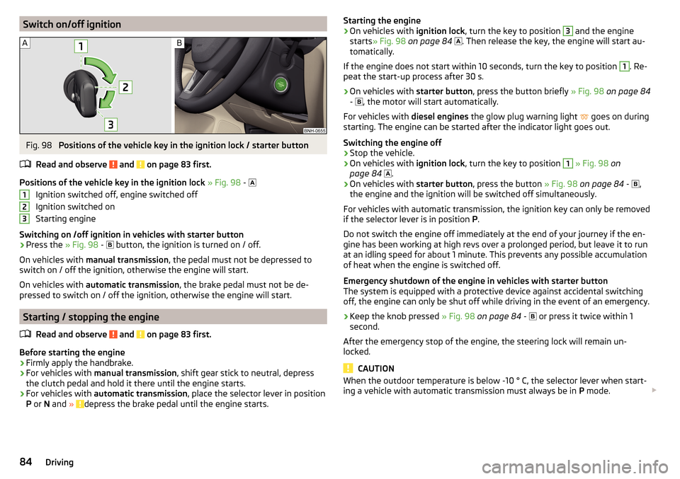
Switch on/off ignitionFig. 98
Positions of the vehicle key in the ignition lock / starter button
Read and observe
and on page 83 first.
Positions of the vehicle key in the ignition lock » Fig. 98 -
Ignition switched off, engine switched off
Ignition switched on
Starting engine
Switching on /off ignition in vehicles with starter button
›
Press the » Fig. 98 -
button, the ignition is turned on / off.
On vehicles with manual transmission , the pedal must not be depressed to
switch on / off the ignition, otherwise the engine will start.
On vehicles with automatic transmission , the brake pedal must not be de-
pressed to switch on / off the ignition, otherwise the engine will start.
Starting / stopping the engine
Read and observe
and on page 83 first.
Before starting the engine
›
Firmly apply the handbrake.
›
For vehicles with manual transmission , shift gear stick to neutral, depress
the clutch pedal and hold it there until the engine starts.
›
For vehicles with automatic transmission , place the selector lever in position
P or N and » depress the brake pedal until the engine starts.
123Starting the engine›On vehicles with ignition lock, turn the key to position 3 and the engine
starts » Fig. 98 on page 84
. Then release the key, the engine will start au-
tomatically.
If the engine does not start within 10 seconds, turn the key to position 1
. Re-
peat the start-up process after 30 s.
›
On vehicles with starter button, press the button briefly » Fig. 98 on page 84
-
, the motor will start automatically.
For vehicles with diesel engines the glow plug warning light
goes on during
starting. The engine can be started after the indicator light goes out.
Switching the engine off
›
Stop the vehicle.
›
On vehicles with ignition lock, turn the key to position
1
» Fig. 98 on
page 84
.
›
On vehicles with
starter button, press the button » Fig. 98 on page 84 -
,
the engine and the ignition will be switched off simultaneously.
For vehicles with automatic transmission, the ignition key can only be removed
if the selector lever is in position P.
Do not switch the engine off immediately at the end of your journey if the en-
gine has been working at high revs over a prolonged period, but leave it to run
at an idling speed for about 1 minute. This prevents any possible accumulation
of heat when the engine is switched off.
Emergency shutdown of the engine in vehicles with starter button
The system is equipped with a protective device against accidental switching
off, the engine can only be shut off while driving in the event of an emergency.
›
Keep the knob pressed » Fig. 98 on page 84 -
or press it twice within 1
second.
After the emergency stop of the engine, the steering lock will remain un-
locked.
CAUTION
When the outdoor temperature is below -10 ° C, the selector lever when start-
ing a vehicle with automatic transmission must always be in P mode. 84Driving
Page 87 of 184
Note■The engine running noises may be louder at first for a short time after start-
ing the cold engine.■
You should not switch on any major electrical components during the heat-
ing period, otherwise the vehicle battery will be drained unnecessarily.
■
After switching off the ignition, the radiator fan may (also intermittently)
continue to operate for approx. 10 minutes.
Problems with the engine start - vehicles with starter button
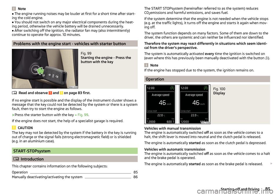
Fig. 99
Starting the engine - Press the
button with the key
Read and observe and on page 83 first.
If no engine start is possible and the display of the instrument cluster shows a
message that the key could not be detected by the system or there is a system
fault, then try to start the engine as follows.
›
Press the starter button with the key » Fig. 99.
If the engine does not start, the help of a specialist garage is required.
CAUTION
The key may not be detected by the system if the battery in the key is running
out of charge or the signal fails (strong electromagnetic field) or is shielded
(e.g. in an aluminium case).
START-STOPsystem
Introduction
This chapter contains information on the following subjects:
Operation
85
Manually deactivating/activating the system
86The START STOPsystem (hereinafter referred to as the system) reduces
CO 2emissions and harmful emissions, and saves fuel.
If the system determine that the engine is not needed when the vehicle stops
(e.g. at the traffic lights), it turns off the engine and starts it again when mov-
ing off.
The system function depends on many factors. Some of them are down to the
driver, the others are systemic and can neither be influenced nor identified.
Therefore the system may react differently in situations which seem identi-
cal from the driver's perspective.
The system is automatically activated every time the ignition is switched on
(even where this has previously been manually deactivated with the button ).
Note
If the engine has stopped due to the system, the ignition remains on.
Operation
Fig. 100
Display
Vehicles with manual transmission
The engine is automatically switched off as soon as the vehicle comes to a
halt, the shift lever is moved into neutral and the clutch pedal is released.
The engine is automatically started as soon as the clutch pedal is depressed.
Vehicles with automatic transmission
The engine is automatically switched off as soon as the vehicle comes to a halt
and the brake pedal is operated.
The engine is automatically started as soon as the brake pedal is released.
85Starting-off and Driving
Page 88 of 184
Requirements for the system to function correctly
The following conditions must be met for the system to function correctly.
The driver's door is closed.
The driver has fastened the seat belt.
The driving speed was higher than 4 km/h after the last stop.
No trailer or other accessory is connected to the trailer socket.
System status
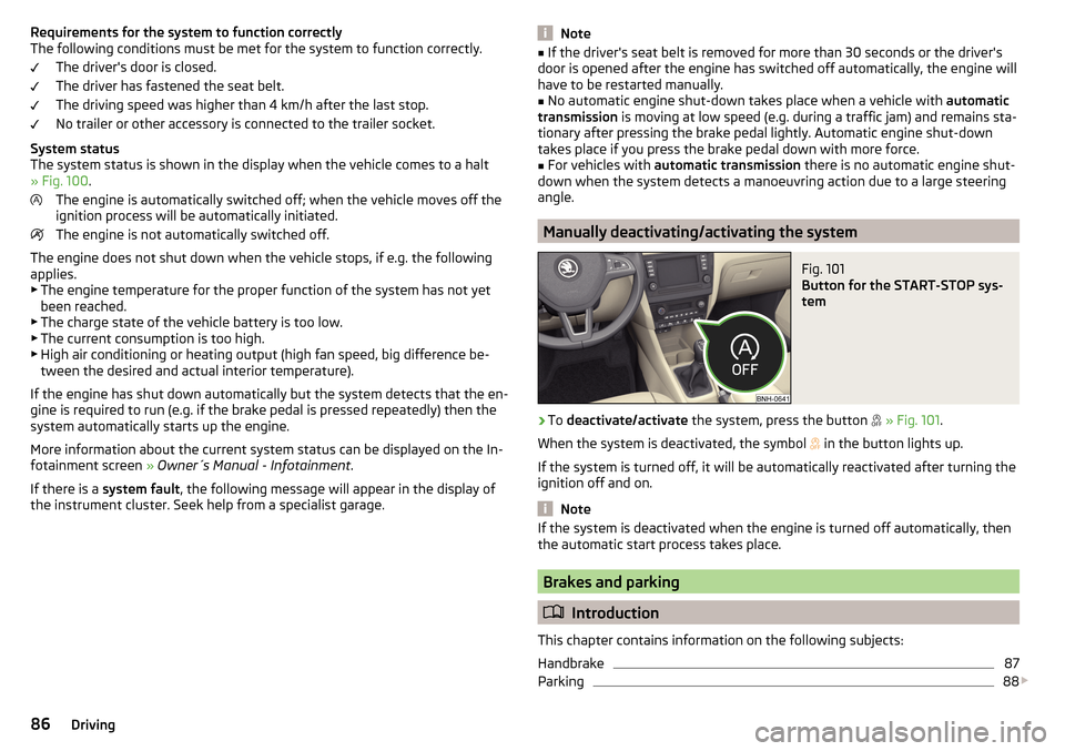
The system status is shown in the display when the vehicle comes to a halt
» Fig. 100 .
The engine is automatically switched off; when the vehicle moves off the
ignition process will be automatically initiated.
The engine is not automatically switched off.
The engine does not shut down when the vehicle stops, if e.g. the following
applies.
▶ The engine temperature for the proper function of the system has not yet
been reached.
▶ The charge state of the vehicle battery is too low.
▶ The current consumption is too high.
▶ High air conditioning or heating output (high fan speed, big difference be-
tween the desired and actual interior temperature).
If the engine has shut down automatically but the system detects that the en- gine is required to run (e.g. if the brake pedal is pressed repeatedly) then the
system automatically starts up the engine.
More information about the current system status can be displayed on the In-
fotainment screen » Owner´s Manual - Infotainment .
If there is a system fault , the following message will appear in the display of
the instrument cluster. Seek help from a specialist garage.Note■ If the driver's seat belt is removed for more than 30 seconds or the driver's
door is opened after the engine has switched off automatically, the engine will
have to be restarted manually.■
No automatic engine shut-down takes place when a vehicle with automatic
transmission is moving at low speed (e.g. during a traffic jam) and remains sta-
tionary after pressing the brake pedal lightly. Automatic engine shut-down
takes place if you press the brake pedal down with more force.
■
For vehicles with automatic transmission there is no automatic engine shut-
down when the system detects a manoeuvring action due to a large steering
angle.
Manually deactivating/activating the system
Fig. 101
Button for the START-STOP sys-
tem
›
To deactivate/activate the system, press the button
» Fig. 101 .
When the system is deactivated, the symbol
in the button lights up.
If the system is turned off, it will be automatically reactivated after turning the ignition off and on.
Note
If the system is deactivated when the engine is turned off automatically, then
the automatic start process takes place.
Brakes and parking
Introduction
This chapter contains information on the following subjects:
Handbrake
87
Parking
88
86Driving
Page 89 of 184
The wear and tear on the brake pads is dependent on the operating condi-
tions and driving style. In difficult conditions (e.g. urban, sporty driving), the
condition of the brakes should be checked between services by a specialist ga-
rage.
Brake response can be slower if the brakes are covered in moisture or, in win-
ter, have a layer of ice or salt on them . The brakes should be cleaned and
dried by applying the brakes many times over »
.
Corrosion on the brake discs and dirt on the brake pads can occur if the vehicle
has been parked for a long period and if you do not make much use of the
braking system. The brakes are cleaned by applying the brakes several times
over »
.
Before negotiating a long or steep gradient , reduce speed and shift down a
gear. As a result, the braking effect of the engine will be used, reducing the
load on the brakes. If, nevertheless, there is a need for additional braking, it
should be carried out at intervals.
Emergency braking warning - if it is necessary to brake hard, the system may
cause the brake lights to automatically flash, to alert the traffic behind.
New brake pads must first be ““run in”” because these do not initially have the
best possible braking effect. Drive especially carefully for the first 200 km or
so.
If the brake fluid level is too low, it can cause faults in the braking system ;
the warning light will illuminate in the instrument cluster
» page 30,
Braking system
. If the warning light does not light up, yet the stopping dis-
tance is perceived to be longer than before, the driving style should be adap-
ted in view of the unknown cause of the problem, and braking kept to a mini-
mum - seek the help of a specialist garage without delay.
The brake booster increases the pressure generated with the brake pedal. The
brake booster only operates when the engine is running.
WARNING■ Greater physical effort is required for braking when the engine is switch-
ed off – risk of accident!■
The clutch pedal must be actuated when braking on a vehicle with man-
ual transmission, when the vehicle is in gear and at low revs. Otherwise,
the functionality of the brake system may be impaired – risk of accident!
WARNING (Continued)■ Do not depress the brake pedal, if there is no requirement to slow down.
This causes the brakes to overheat and can also result in a longer braking
distance and excessive wear - risk of accident!■
Only brake for the purpose of drying and cleaning the brake discs if the
traffic conditions permit this. Do not place any other road users in jeopardy.
■
Recommendations for new brake pads should be followed.
■
When stopping and parking, the parking brake should always be applied
firmly, otherwise the vehicle could move off - risk of accident!
■
If a front spoiler, full wheel trim, etc. is mounted retrospectively, it must
be ensured that the air supply to the front wheel brakes is not reduced.
Otherwise, the front brakes could be in danger of overheating – risk of acci-
dent!
Handbrake
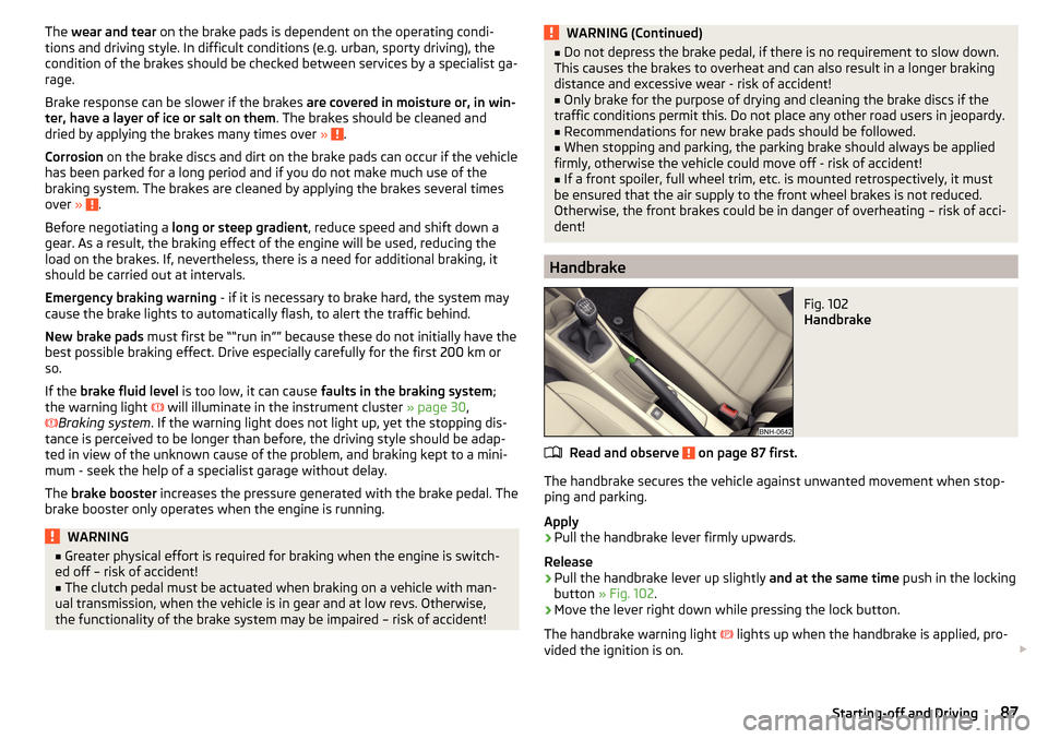
Fig. 102
Handbrake
Read and observe on page 87 first.
The handbrake secures the vehicle against unwanted movement when stop-
ping and parking.
Apply
›
Pull the handbrake lever firmly upwards.
Release
›
Pull the handbrake lever up slightly and at the same time push in the locking
button » Fig. 102 .
›
Move the lever right down while pressing the lock button.
The handbrake warning light
lights up when the handbrake is applied, pro-
vided the ignition is on.
87Starting-off and Driving
Page 93 of 184
Starting-off and drivingRead and observe
and on page 89 first.
Moving off and pausing temporarily
›
Firmly depress and hold the brake pedal.
›
Start the engine.
›
Press the locking button and move the selector lever to the desired position
» page 89 .
›
Release the brake pedal and accelerate.
The selector lever position N does not have to be selected when stopping for a
short time (e.g. at a crossroads). However, the brake pedal should be de-
pressed, in order to prevent the vehicle from rolling.
Accelerating at maximum speed during the journey (kickdown function)
If the accelerator pedal is depressed while the vehicle is in forward drive mode,
the kick-down function is turned on.
The gear change is adjusted accordingly to achieve maximum acceleration.
WARNINGRapid acceleration ( e.g. on slippery roads) can lead to a loss of control over
the vehicle – risk of accident!
Running in and economical driving
Introduction
This chapter contains information on the following subjects:
Running in the engine
91
Tips on economical driving
91
DriveGreen function
91
Running in the engine
During the first 1,500 km, the driving style is decisive for the success of the
running in process.
During the first 1,000 km , the engine should not be charged with more than
3/4 of the maximum permitted engine revs and without the trailer.
From about 1,000 to 1,500 km , the engine can be pushed up to the maximum
permitted engine speed.
Tips on economical driving
Fuel consumption depends on the driving style, road and weather conditions,
and similar such factors.
For an economical driving style, the following instructions must be observed. ▶ Avoid unnecessary acceleration and braking.
▶ Engage the recommended gear » page 38.
▶ Avoid full throttle and high speeds.
▶ Reduce idling.
▶ Avoid short distances.
▶ Ensure the correct tyre inflation pressure is maintained » page 134.
▶ Avoid unnecessary ballast.
▶ Remove the roof rack before driving if it is not needed.
▶ Only turn on electrical consumers (e.g. seat heating) for as long as necessary.
▶ Briefly ventilate before turning on the cooling system, do not use the cooling
system with the windows open.
▶ Do not leave windows open at high speeds.
DriveGreen function
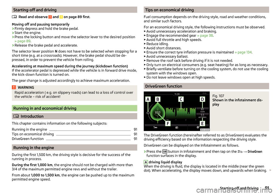
Fig. 107
Shown in the infotainment dis-
play
The DriveGreen function (hereinafter referred to as DriveGreen) evaluates the
driving efficiency based on the information respecting the driving style.
DriveGreen can be displayed on the Infotainment as follows.
›
Press the button in Infotainment and then tap on the
→
DriveGreen
function surfaces in the display.
A
driving liquid display
When the driving is fluid, the display is located in the middle (near the green
dot). When accelerating, the display moves down, and upwards when braking.
91Starting-off and Driving
Page 95 of 184
The following instructions must be observed if vehicle damage is to be avoided
when driving through water (e.g. flooded roads).›
Therefore determine the depth of the water before driving through water.
The water level must not go above the web of the lower beam » Fig. 108.
›
Drive at no more than walking pace, otherwise a wave may form in front of
the vehicle, which could cause the water to enter into the vehicle’s systems
(e.g. the air intake system for the engine).
›
Never stop in the water, do not reverse and do not switch the engine off.
CAUTION
■ If water gets into the vehicle’s systems (e.g. the air intake system for the en-
gine) it can cause serious damage to the vehicle!■
Oncoming vehicles can generate water waves which can exceed the permis-
sible water level for your vehicle.
■
Do not drive through salt water, as the salt can cause corrosion. A vehicle
coming into contact with salt water is to be thoroughly rinsed with fresh wa-
ter.
Assist systems
General information
Introduction
WARNING■
The assistance systems only serve to support and do not relieve the driv-
er of the responsibility for driving the vehicle.■
The increased safety provision, as well as the increased occupant protec-
tion provided by the assistance systems must not tempt you to take risks -
risk of accident!
■
Adjust the speed and driving style to the current visibility, weather, road
and traffic conditions.
■
The assistance systems have physical and system-related limitations. For
this reason, the driver may experience some undesired or delayed system
responses in certain situations. You should therefore always be alert and
ready to intervene!
■
Only enable, disable or set the assistance systems so that you have the
vehicle fully under control in every traffic situation - risk of accident!
Braking and stabilisation systems
Introduction
This chapter contains information on the following subjects:
Stability Control (ESC)
94
Anti-lock braking system (ABS)
94
Engine drag torque control (MSR)
94
Traction control (TCS)
94
Electronic Differential Lock (EDL)
95
Brake Assist (HBA)
95
Hill Start Assist (HHC)
95
Multi collision brake (MCB)
95
Trailer stabilization system (TSA)
95
The brake and stabilization systems are automatically activated each time the
ignition is switched on, unless otherwise indicated.
The error display is in Chapter » page 29, Warning lights .
93Assist systems
Page 99 of 184
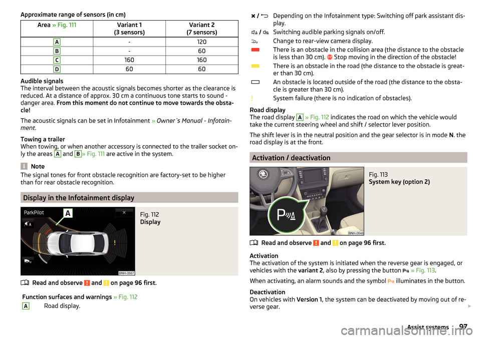
Approximate range of sensors (in cm)Area » Fig. 111Variant 1
(3 sensors)Variant 2
(7 sensors)A-120B-60C160160D6060
Audible signals
The interval between the acoustic signals becomes shorter as the clearance is
reduced. At a distance of approx. 30 cm a continuous tone starts to sound -
danger area. From this moment do not continue to move towards the obsta-
cle!
The acoustic signals can be set in Infotainment » Owner´s Manual - Infotain-
ment .
Towing a trailer
When towing, or when another accessory is connected to the trailer socket on-
ly the areas
A
and
B
» Fig. 111 are active in the system.
Note
The signal tones for front obstacle recognition are factory-set to be higher
than for rear obstacle recognition.
Display in the Infotainment display
Fig. 112
Display
Read and observe and on page 96 first.
Function surfaces and warnings » Fig. 112ARoad display. Depending on the Infotainment type: Switching off park assistant dis-
play. Switching audible parking signals on/off.Change to rear-view camera display.There is an obstacle in the collision area (the distance to the obstacle
is less than 30 cm).
Stop moving in the direction of the obstacle!There is an obstacle in the road (the distance to the obstacle is great-
er than 30 cm).An obstacle is located outside of the road (the distance to the obsta-
cle is greater than 30 cm).System failure (there is no indication of obstacles).
Road display
The road display
A
» Fig. 112 indicates the road on which the vehicle would
take the current steering wheel and shift / selector lever position.
The shift lever is in the neutral position and the gear selector is in mode N. the
road display is at the front.
Activation / deactivation
Fig. 113
System key (option 2)
Read and observe and on page 96 first.
Activation
The activation of the system is initiated when the reverse gear is engaged, or
vehicles with the variant 2, also by pressing the button
» Fig. 113 .
When activating, an alarm sounds and the symbol illuminates in the button.
Deactivation
On vehicles with Version 1, the system can be deactivated by moving out of re-
verse gear.
97Assist systems
Page 107 of 184
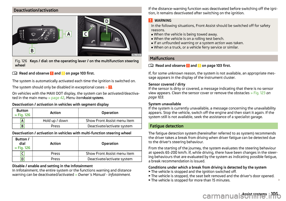
Deactivation/activationFig. 126
Keys / dial: on the operating lever / on the multifunction steering
wheel
Read and observe
and on page 103 first.
The system is automatically activated each time the ignition is switched on.The system should only be disabled in exceptional cases »
.
On vehicles with the MAXI DOT display, the system can be activated/deactiva- ted in the main menu » page 42, Menu item
Assist systems
.
Deactivation / activation in vehicles with segment display
Button
» Fig. 126ActionOperationAHold up / downShow Front Assist menu itemBPressDeactivate/activate system
Deactivation / activation in vehicles with multi-function steering wheel
Button / dial
» Fig. 126ActionOperation
CPressShow Front Assist menu itemDPressDeactivate/activate system
Disable / enable and setting in the Infotainment
In Infotainment, the entire system or the functions warning and distance
warning can be deactivated/activated » Owner´s Manual - Infotainment .
If the distance-warning function was deactivated before switching off the igni-
tion, it remains deactivated after switching on the ignition.WARNINGIn the following situations, Front Assist should be switched off for safety
reasons.■
When the vehicle is being towed away.
■
When the vehicle is on a rolling test bench.
■
If an unfounded warning or a system action was taken.
■
When on a truck, or a vehicle ferry service or similar.
Malfunctions
Read and observe
and on page 103 first.
If, for some unknown reason, the system is not available, an appropriate mes-
sage appears in the display of the instrument cluster.
Sensor covered / dirty
If the sensor is dirty or covered, a message indicating that there is no sensor
view appears. Clean the sensor cover or remove the obstacles » Fig. 123 on
page 103 .
System unavailable
If the system is currently unavailable, a message concerning the unavailability
appears. Stop the vehicle, switch off the engine and then start it again. If the
system still is not available, seek the assistance of a specialist garage.
Fatigue detection
The fatigue detection system (hereinafter referred to as system) recommends
the driver takes a break from driving when driver fatigue can be detected due
to the driver's steering behaviour.
From the starting of the journey, the system evaluates the steering behaviour
at speeds 65-200 km/h. If, while driving, there have been changes in the steer-
ing behaviours that are evaluated by the system as indicating possible fatigue,
a break recommendation is issued.
Conditions under which a break from driving is detected by the system ▶ The vehicle is stopped and the ignition switched off.
▶ The vehicle is stopped, the seat belt removed and the driver's door opened.
▶ The vehicle is stopped for more than 15 minutes.
105Assist systems
Page 133 of 184
Specification - the brake fluid must comply with the standard VW 501 14 (this
standard meets the requirements of FMVSS 116 DOT4).WARNING■ The following instructions must be followed at all times when working on
the engine compartment » page 125.■
If the fluid level drops significantly within a short time or if it drops below
the “MIN” » Fig. 150mark, this may be an indication of a leak in the brake
system.
Stop driving - There is a risk of an accident! Seek help from a
specialist garage.
Note
■ The brake fluid is changed as part of a compulsory inspection service.■Too low brake fluid level is indicated by the warning light being shown on
the display of the instrument cluster as well as the corresponding message
» page 30 . We still recommend inspecting the brake fluid level in the reservoir
from time to time.
Vehicle battery
Introduction
This chapter contains information on the following subjects:
Check condition
132
Charging
132
Disconnect/reconnect and change
133
The vehicle battery represents a power source for the motor to start and for the supply of electrical consumers in the car.
Depending on the engine, the vehicle battery is either in the engine compart-
ment or the luggage compartment.
Automatic shutdown of consumers - vehicle battery discharge protection
The on-board power supply system tries to prevent the vehicle battery from
discharging in the following ways when it is subject to heavy loading. ▶ By increasing the engine idle speed.
▶ Through the power limitation of certain consumers.
▶ By switching off some consumers (heated seats, heated rear window) for as
long as necessary.
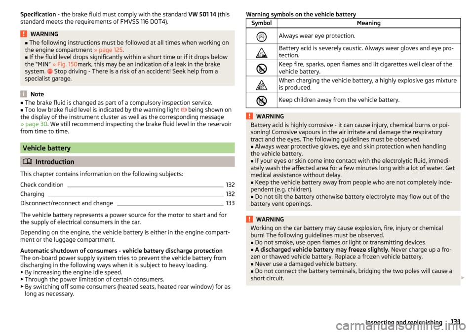
Warning symbols on the vehicle batterySymbolMeaningAlways wear eye protection.Battery acid is severely caustic. Always wear gloves and eye pro-
tection.Keep fire, sparks, open flames and lit cigarettes well clear of the
vehicle battery.When charging the vehicle battery, a highly explosive gas mixture
is produced.Keep children away from the vehicle battery.WARNINGBattery acid is highly corrosive - it can cause injury, chemical burns or poi-
soning! Corrosive vapours in the air irritate and damage the respiratory
tract and the eyes. The following guidelines must be observed.■
Always wear protective gloves, eye and skin protection when handling
the vehicle battery.
■
If your eyes or skin come into contact with the electrolytic fluid, immedi-
ately wash the affected area for a few minutes long with a lot of water. Get
medical assistance without delay.
■
Keep the vehicle battery away from people who are not completely inde-
pendent (e.g. children).
■
Do not tilt the battery otherwise battery electrolyte may flow out of the
battery vent openings.
WARNINGWorking on the car battery may cause explosion, fire, injury or chemical
burn! The following guidelines must be observed.■
Do not smoke, use open flames or light or transmitting devices.
■
A discharged vehicle battery may freeze slightly. Never charge up a fro-
zen or thawed vehicle battery. Replace a frozen vehicle battery.
■
Never use a damaged vehicle battery.
■
Do not connect the battery terminals, bridging the two poles will cause a
short circuit.
131Inspecting and replenishing
Page 134 of 184
CAUTIONEnsure that battery acid does not come into contact with the bodywork – risk
of damage to the paintwork.
Note
■ We recommend having all work on the vehicle battery carried out by a spe-
cialist garage.■
You should replace batteries older than 5 years.
Check condition
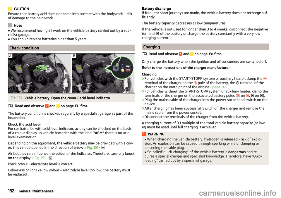
Fig. 151
Vehicle battery: Open the cover / acid level indicator
Read and observe
and on page 131 first.
The battery condition is checked regularly by a specialist garage as part of the
inspection.
Check the acid level
For car batteries with acid level indicator, acidity can be checked on the basis
of a colour display. In vehicle batteries with the label “AGM” there is no acid
level examination.
Depending on the equipment, the vehicle battery may be provided with a cov-
er, this can be opened in the direction of arrow » Fig. 151 -
.
Air bubbles can influence the colour of the indicator. Therefore, carefully knock
on the display » Fig. 151 -
.
Black colour – electrolyte level is correct.
Colourless or light yellow colour – electrolyte level too low, the battery must
be replaced.
Battery discharge
If frequent short journeys are made, the vehicle battery does not recharge suf-
ficiently.
The battery capacity decreases at low temperatures.
If the vehicle is not used for longer than 3 to 4 weeks, disconnect the negative
terminal
of the battery or charge the battery constantly with a very low
charging current.
Charging
Read and observe
and on page 131 first.
Only charge the battery when the ignition and all consumers are switched off.
Refer to the instructions of the charger manufacturer.
Charging
›
For vehicles with the START-STOPP system or auxiliary heater, clamp the
terminal of the charger on the pole of the battery, the
terminal of the
charger on the earth point of the engine » page 145.
›
For vehicles without the START-STOPP system or auxiliary heater, clamp the
terminals of the charger on the associated battery poles ( on
,
on
).
›
Plug the mains cable of the charger into the power socket and switch on the
device.
›
After charging has been successful: Switch off the charger and remove the
mains cable from the power socket.
›
Disconnect the terminals of the charger from the vehicle battery.
A charging current of 0.1 multiple of the total vehicle battery capacity (or low-
er) must be used until full charging is achieved.
WARNING■ When charging the vehicle battery, hydrogen is released - risk of explo-
sion. An explosion can be caused through sparking while unclamping or
loosening the cable plug.■
So-called“quick-charging” of the vehicle battery is dangerous and re-
quires a special charger and specialist knowledge. Therefore, have “Quick
loading” carried out by a specialist garage.
132General Maintenance