engine coolant SKODA RAPID SPACEBACK 2013 1.G Owner's Manual
[x] Cancel search | Manufacturer: SKODA, Model Year: 2013, Model line: RAPID SPACEBACK, Model: SKODA RAPID SPACEBACK 2013 1.GPages: 193, PDF Size: 14.8 MB
Page 5 of 193
Table of Contents
Abbreviations
Safety
Passive Safety
6
General information
6
Correct and safe seated position
7
Seat belts
10
Using seat belts
10
Inertia reels and belt tensioners
13
Airbag system
14
Description of the airbag system
14
Airbag overview
15
Deactivating airbags
18
Transporting children safely
20
Child seat
20
Fastening systems
22
Using the system
Cockpit
25
Overview
24
Instruments and Indicator Lights
26
Instrument cluster
26
Indicator lights
30
Information system
37
Driver information system
37
Multifunction display (MFD)
39
MAXI DOT display
42
Service interval display
43
Unlocking and opening
45
Unlocking and locking
45
Anti-theft alarm system
49Luggage compartment lid50Electric power windows51
Lights and visibility
53
Lights
53
Interior lighting
58
Visibility
59
Windscreen wipers and washers
60
Rear mirror
62
Seats and head restraints
64
Seats and head restraints
64
Seat features
66
Transporting and practical equipment
68
Useful equipment
68
Luggage compartment
75
Variable loading floor in the luggage
compartment (Estate)
80
Roof rack system
83
Heating and air conditioning
84
Heating, ventilation, cooling
84
Communication and multimedia
89
Universal telephone installation GSM II
89
Voice control
93
Multimedia
94
Driving
Starting-off and Driving
97
Starting and turning off the engine
97
Brakes and parking
99
Manual gear changing and pedals
100
Automatic gearbox
101
Driving in an economical driving style
104
Driving through water and driving off made-
up roads
105Assist systems106Braking and stabilisation systems106
Parking aid
107
Cruise Control System
108
START-STOP
109
Hitch and trailer
112
Hitch
112
Trailer
116
General Maintenance
Care and maintenance
119
Service work, adjustments and technical alterations
119
Washing vehicle
122
Cleaning vehicle exterior
123
Interior care
126
Inspecting and replenishing
129
Fuel
129
Engine compartment
131
Engine oil
134
Coolant
136
Brake fluid
137
Vehicle battery
138
Wheels
142
Tyres and wheel rims
142
Tyre control display
145
Reserve and temporary spare wheel
146
Winter operation
147
Do-it-yourself
Emergency equipment and self-help
149
Emergency equipment
149
Changing a wheel
151
Tyre repair
155
Jump-starting
157
Towing the vehicle
1583Table of Contents
Page 8 of 193
Safety
Passive Safety
General information
Introduction
This chapter contains information on the following subjects:
Before setting off
6
Driving safety
6
Safety equipment
6
In this section you will find important information, tips and notes on the sub-
ject of passive safety in your vehicle.
We have combined everything here which you should be familiar with, for ex-
ample, regarding seat belts, airbags, child seats and safety of children.
WARNING■ This chapter contains important information on how to use the vehicle for
the driver and his occupants.■
You can find further information on safety concerning you and those trav-
elling with you in the following chapters of this owner's manual.
■
The complete on-board literature should always be in the vehicle. This
applies in particular, if you rent out or sell the vehicle.
Before setting off
Read and observe
on page 6 first.
For your own safety and the safety of the people travelling with you, please
pay attention to the following points before setting off.
Ensure that the lighting and the turn signal system are functioning proper-
ly.
Ensure that the function of the wipers and the condition of the wiper
blades are free of any defects.
Ensure that all of the windows offer good visibility to the outside.
Adjust the rear-view mirror so that vision to the rear is guaranteed.
Ensure that the mirrors are not covered.
Check the tyre inflation pressure.
Check the engine oil, brake fluid and coolant level.
Secure all items of luggage.
Do not exceed the permissible axle loads and permissible gross weight of
the vehicle.
Close all doors as well as the bonnet and boot lid.
Ensure that no objects can obstruct the pedals.
Protect children in suitable child seats with correctly fastened seat
belts » page 20 , Transporting children safely .
Adopt the correct seated position » page 7, Correct and safe seated
position . Tell your passengers to assume the correct seated position.
Driving safety
Read and observe
on page 6 first.
The driver is fully responsible for himself and his occupants. If your driving
safety is effected, you place yourself and the oncoming traffic at risk.
The following guidelines must therefore be observed. Do not become distracted from concentrating on the traffic situation, e.g.
by your passengers or mobile phone calls.
Never drive when your driving ability is impaired, e.g. due to medication, al-
cohol or drugs.
Keep to the traffic regulations and the permissible speed limit.
Always adjust the driving speed to the road, traffic and weather condi-
tions.
Take regular breaks on long journeys – at least every two hours.
Safety equipment
Read and observe
on page 6 first.
The following list contains only part of the safety equipment in your vehicle.
› Three-point seat belts for all the seats.
› Belt force limiters for the front seats.
› Belt tensioners for the front seats.
› Seat belt height adjusters for the front seats.
› Front airbag for the driver and the front passenger.
› Side airbags.
6Safety
Page 28 of 193
Instruments and Indicator Lights
Instrument cluster
Introduction
This chapter contains information on the following subjects:
Overview
26
Revolution counter
27
Display
27
Speedometer
27
Coolant temperature gauge
27
Fuel gauge
28
Counter for distance driven
28
29
Display of the second speed
29
Auto Check Control
29
The instrument cluster gives the driver basic information such as the current
speed, engine speed, the state of some vehicle systems and the like.
Fault display
If there is a fault in the instrument cluster, the Error message will appear in
the display.
Seek help from a specialist garage.
WARNINGConcentrate fully at all times on your driving! As the driver you are fully re-
sponsible for road safety.
Note
When the ignition is on, the instrument cluster is illuminated 1)
. The brightness
level is automatically adjusted depending on the ambient lighting.OverviewFig. 19
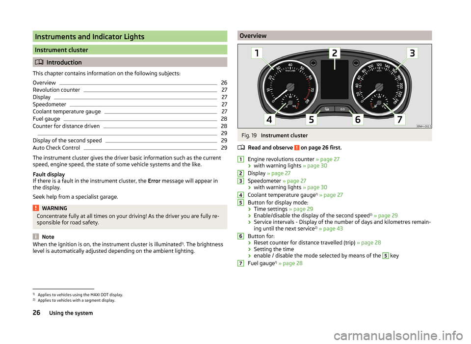
Instrument cluster
Read and observe
on page 26 first.
Engine revolutions counter » page 27
› with warning lights
» page 30
Display » page 27
Speedometer » page 27
› with warning lights
» page 30
Coolant temperature gauge 1)
» page 27
Button for display mode:
› Time settings
» page 29
› Enable/disable the display of the second speed 2)
» page 29
› Service intervals - Display of the number of days and kilometres remain-
ing until the next service 2)
» page 43
Button for: › Reset counter for distance travelled (trip)
» page 28
› Setting the time
› enable / disable the mode selected by means of the
5
key
Fuel gauge 1)
» page 28
12345671)
Applies to vehicles using the MAXI DOT display.
2)
Applies to vehicles with a segment display.
26Using the system
Page 29 of 193
Revolution counterRead and observe
on page 26 first.
The tachometer
1
» Fig. 19 on page 26 shows the actual engine speed per mi-
nute.
The beginning of the red scale range of the tachometer indicates the maxi-
mum permitted engine speed of a driven-in and operating warm engine.
You should shift into the next highest gear before the red scale of the revolu- tion counter is reached, or select mode D on the automatic gearbox.
The gear recommendation is important to note in order to maintain the opti-
mum engine speed » page 38.
CAUTION
The pointer of the tachometer must reach the red area for only a short time -
there is a risk of engine damage!
Display
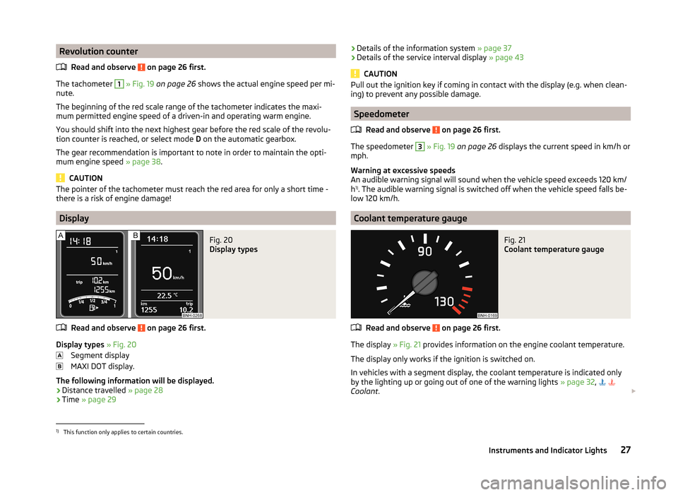
Fig. 20
Display types
Read and observe on page 26 first.
Display types » Fig. 20
Segment display
MAXI DOT display.
The following information will be displayed.
› Distance travelled
» page 28
› Time
» page 29
›Details of the information system
» page 37
› Details of the service interval display
» page 43
CAUTION
Pull out the ignition key if coming in contact with the display (e.g. when clean-
ing) to prevent any possible damage.
Speedometer
Read and observe
on page 26 first.
The speedometer
3
» Fig. 19 on page 26 displays the current speed in km/h or
mph.
Warning at excessive speeds
An audible warning signal will sound when the vehicle speed exceeds 120 km/
h 1)
. The audible warning signal is switched off when the vehicle speed falls be-
low 120 km/h.
Coolant temperature gauge
Fig. 21
Coolant temperature gauge
Read and observe on page 26 first.
The display » Fig. 21 provides information on the engine coolant temperature.
The display only works if the ignition is switched on.
In vehicles with a segment display, the coolant temperature is indicated only by the lighting up or going out of one of the warning lights » page 32,
Coolant .
1)
This function only applies to certain countries.
27Instruments and Indicator Lights
Page 30 of 193
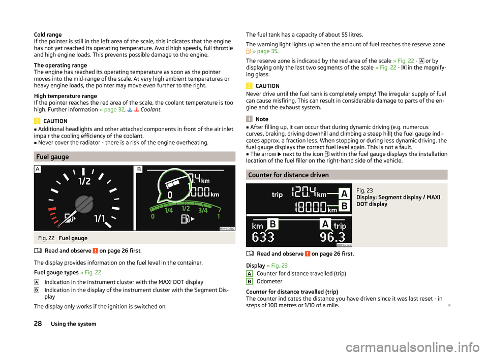
Cold range
If the pointer is still in the left area of the scale, this indicates that the engine
has not yet reached its operating temperature. Avoid high speeds, full throttle
and high engine loads. This prevents possible damage to the engine.
The operating range
The engine has reached its operating temperature as soon as the pointer
moves into the mid-range of the scale. At very high ambient temperatures or
heavy engine loads, the pointer may move even further to the right.
High temperature range
If the pointer reaches the red area of the scale, the coolant temperature is too high. Further information » page 32,
Coolant .
CAUTION
■
Additional headlights and other attached components in front of the air inlet
impair the cooling efficiency of the coolant.■
Never cover the radiator - there is a risk of the engine overheating.
Fuel gauge
Fig. 22
Fuel gauge
Read and observe
on page 26 first.
The display provides information on the fuel level in the container.
Fuel gauge types » Fig. 22
Indication in the instrument cluster with the MAXI DOT display
Indication in the display of the instrument cluster with the Segment Dis-
play
The display only works if the ignition is switched on.
The fuel tank has a capacity of about 55 litres.
The warning light lights up when the amount of fuel reaches the reserve zone
» page 35 .
The reserve zone is indicated by the red area of the scale » Fig. 22 -
or by
displaying only the last two segments of the scale » Fig. 22 -
in the magnify-
ing glass.
CAUTION
Never drive until the fuel tank is completely empty! The irregular supply of fuel
can cause misfiring. This can result in considerable damage to parts of the en-
gine and the exhaust system.
Note
■ After filling up, it can occur that during dynamic driving (e.g. numerous
curves, braking, driving downhill and climbing a steep hill) the fuel gauge indi-
cates approx. a fraction less. When stopping or during less dynamic driving, the
fuel gauge displays the correct fuel level again. This is not a fault.■
The arrow
next to the icon
within the fuel gauge displays the installation
location of the fuel filler on the right-hand side of the vehicle.
Counter for distance driven
Fig. 23
Display: Segment display / MAXI
DOT display
Read and observe on page 26 first.
Display » Fig. 23
Counter for distance travelled (trip)
Odometer
Counter for distance travelled (trip)
The counter indicates the distance you have driven since it was last reset - in
steps of 100 metres or 1/10 of a mile.
AB28Using the system
Page 32 of 193
The following message is shown in the MAXI DOT display.Gearbox overheated. Stop! Log book!
do not continue to drive! Stop the vehicle, switch off the engine, and wait
until the
icon goes out – risk of gearbox damage! You can continue your
journey as soon as the symbol disappears.WARNINGIf you have to stop for technical reasons, then park the vehicle at a safe
distance from the traffic, switch off the engine and switch on the hazard
warning lights » page 57. The warning triangle must be set up at the pre-
scribed distance - observe the national legal provisions when doing so.
Note
■ If the MAXI DOT display shows warning messages, these messages must be
confirmed in order to access the main menu » page 37, Using the informa-
tion system .■
As long as the operational faults are not rectified, the symbols are always in-
dicated again. After they are displayed for the first time, the symbols continue
to be indicated without any extra messages for the driver.
Indicator lights
Introduction
This chapter contains information on the following subjects:
Handbrake
30
Brake system
31
Seat belt warning light
31
Generator
31
Door open
31
Engine oil
31
Coolant
32
Power steering
32
Stability Control (ESC)
32
Traction control (ASR)
33
Antiblock brake system (ABS)
33
Rear fog light
33
Lamp failure
33 Exhaust inspection system34 Glow plug system (diesel engine)34
Engine performance check (petrol engine)
34
Diesel particle filter (diesel engine)
34
Fuel reserve
35
Airbag system
35
Tyre inflation pressure
35
Windscreeen washer fluid
36
Turn signal system
36
Fog lights
36
Cruise control system
36
Brake pedal (automatic gearbox)
36
Main beam
36
The warning lights indicate certain functions or faults.
Some warning lights can be accompanied by acoustic signals and messages in
the display of the instrument cluster.
After switching on the ignition, some warning lights light up briefly as a func-
tion test.
If the tested systems are OK, the corresponding warning lights go out a few
seconds after switching on the ignition or after starting the engine.
WARNING■ Ignoring illuminated indicator lights and related messages or instructions
in the instrument cluster display may lead to serious personal injury or
damage to the vehicle.■
If you have to stop for technical reasons, then park the vehicle at a safe
distance from the traffic, switch off the engine and switch on the hazard
warning lights » page 57. The warning triangle must be set up at the pre-
scribed distance - observe the national legal provisions when doing so.
■
The engine compartment of your car is a hazardous area. The following
warning instructions must be followed at all times when working in the en-
gine compartment » page 131, Engine compartment .
Handbrake
Read and observe
on page 30 first.
The warning light
illuminates if the handbrake is applied.
30Using the system
Page 34 of 193
›Stop the vehicle, switch off the engine, and check the engine oil lev-
el » page 135 .
The warning light will go out if the bonnet is left open for more than 30 sec-
onds
. If no engine oil has been replenished, the warning light will come on
again after driving about 100 km.
The warning light
flashes (engine oil level sensor faulty)
The following message is shown in the MAXI DOT display.
Oil sensor: Workshop!
If the engine oil level sensor is faulty, the warning light
flashes several
times and an audible signal sounds when the ignition is turned on.
Seek assistance from a specialist garage immediately.
Coolant
Read and observe
on page 30 first.
The warning light
remains illuminated , until the engine reaches operating
temperature 1)
. Avoid high speeds, full throttle and high engine loads.
If the warning light
illuminates or flashes , either the coolant temperature is
too high or the coolant level is too low.
The following message is shown in the MAXI DOT display. Check engine coolant! Log book!
›
Stop the vehicle, switch off the engine and check the coolant lev-
el » page 137 .
›
If the coolant level is too low, add coolant to the reservoir » page 137.
If the warning light
does not illuminate , after adding coolant and switching
on the ignition, you may continue your journey.
If the coolant level is within the specified range and the indicator light is still
illuminated , then there may be a malfunction of the cooling fan.
›
Check the fuse for the radiator fan, replace if necessary » page 165, Fuses in
the engine compartment .
If the coolant level and fan fuse are both OK but the indicator light is never-
theless still illuminated,
do not continue your journey!
Seek help from a specialist garage.WARNING■
Carefully open the coolant expansion bottle. If the engine is hot, the cool-
ing system is pressurized – risk of scalding! It is therefore best to allow the
engine to cool down before removing the cap.■
Do not touch the radiator fan. The radiator fan may switch itself on auto-
matically even if the ignition is off.
CAUTION
■ Additional headlights and other attached components in front of the air inlet
impair the cooling efficiency of the coolant.■
Never cover the radiator - there is a risk of the engine overheating.
Power steering
Read and observe
on page 30 first.
If the warning light
illuminates , there is a fault in the power steering sys-
tem.
The power steering operates with reduced steering assist or does not function
at all.
Seek assistance from a specialist garage immediately.
Stability Control (ESC)
Read and observe
on page 30 first.
The warning light
flashes , to show that the ESC is currently operating.
If the warning light
illuminates , there is a fault in the ESC.
The following message is shown in the MAXI DOT display. Error: Electronic Stability Control (ESC)
or Error: Traction control (ASR)
Seek assistance from a specialist garage immediately.
1)
Applies to vehicles with a segment display.
32Using the system
Page 86 of 193

Heating and air conditioning
Heating, ventilation, cooling
Introduction
This chapter contains information on the following subjects:
Air outlet vents
85
Air distribution control
85
Heating
86
Air conditioning (manual air conditioning)
86
Climatronic (automatic air conditioning)
87
Efficient handling of the cooling system
88
malfunctions
88
The heating and air conditioning ventilate and heat the vehicle interior. The air
conditioning system also cools and dehumidifies the vehicle interior.
The heating effect is dependent upon the coolant temperature, thus full heat
output only occurs when the engine has reached its operating temperature.
The cooling system only operates if the following conditions are met. The cooling system is switched on.
The engine is running.
The outside temperature is above approx. +2 °C.
The blower is switched on.
If the cooling system is switched on, the temperature and air humidity drops in
the vehicle. The cooling system prevents the windows from misting up during
winter months.
It is possible to briefly activate re-circulated air mode to enhance the cooling
effect » page 85 .
WARNING■
For your own safety and that of other road users, ensure that all the win-
dows are free of ice, snow and misting.■
The blower should always be on to prevent the windows from misting up.
WARNING (Continued)■ Under certain circumstances, air at a temperature of about 5 °C can flow
out of the vents when the cooling system is switched on.■
To reduce health risks (e.g. common colds), the following instructions for
the use of the cooling system are to be observed. ■The difference between the indoor temperature and the outdoor air
temperature should not be greater than about 5 ° C.
■ The cooling system is to be turned off about 10 minutes before the end
of the journey.
■ Once a year, a disinfection of the air conditioner or the Climatronic is to
be carried out by a specialist company.
CAUTION
■ The air inlet in front of the windscreen must be free from ice, snow or leaves,
for example, to ensure that the heating and cooling system works properly.■
After switching on the cooling Condensation from the evaporator of the air
conditioning may drip down and form a puddle below the vehicle. This is not a
leak!
■
If the coolant temperature is too high, the cooling system is switched off to
ensure that the engine cools down.
Note
The used air streams out through the vents in the luggage compartment.84Using the system
Page 90 of 193

If you select a temperature higher than +29 ℃, “HI” appears in the display.
At both end positions, Climatronic runs at maximum cooling/heating output
and the temperature is automatically not regulated.
Controlling blower
The Climatronic system controls the blower stages automatically in line with the interior temperature. However, the blower level can be manually adjusted
to suit your particular needs.
If the blower speed is reduced to a minimum, Climatronic is switched off.
The blower speed set is indicated by displaying the corresponding number of
segments (pos. 9
» Fig. 93 ) in the display.
Automatic mode
The automatic mode is used in order to maintain a constant temperature and
to demist the windows in the interior of the car.
To switch on press the
button. The display shows
(pos.
4
» Fig. 93 ).
Automatic mode can be switched off by pressing one of the buttons for the air
distribution or by increasing/decreasing the blower speed. The temperature is
nevertheless regulated.
WARNING■ Do not switch off the Climatronic system for longer than necessary.■Switch on the Climatronic system as soon as the windows mist up.
Note
■Do not stick anything on or cover the interior temperature sensor11 » Fig. 93 ; it could have an unfavourable effect on the Climatronic system.■
During operation of the Climatronic, an increase in engine idle speed can oc-
cur under certain circumstances in order to ensure adequate heating comfort.
■
If the windscreen mists up, press the symbol button
. Press the
but-
ton once the windscreen has demisted.
Efficient handling of the cooling system
Read and observe
and on page 84 first.
The air conditioning system compressor uses power from the engine when in
cooling mode, which will affect the fuel consumption.
It recommended to open the windows or the doors of a vehicle for which the
interior has been strongly heated through the effect of direct sunlight in order
to allow the heated air to escape.
The cooling system should not be on if the windows are open.
For the sake of the environment
Pollutant emissions are also reduced when fuel is saved » page 104.
malfunctions
Read and observe
and on page 84 first.
If the cooling system does not operate at outside temperatures higher than +5
°C, there is a problem in the system. The reasons for this may be.
› One of the fuses has blown. Check the fuse and replace if necessa-
ry » page 163 .
› The cooling system has switched off automatically for a short time because
the coolant temperature of the engine is too hot » page 27.
If you are not able to resolve the operational problem yourself, or if the cooler
output has reduced, switch off the cooling system and seek assistance from a
specialist garage.
88Using the system
Page 119 of 193
Safety eyelet
The safety eyelet B» Fig. 118 serves to attach the breakaway cable of the
trailer.
When attaching the breakaway cable to the safety eyelet, it must sag freely
against the vehicle in all trailer positions (sharp bends, in reverse etc.) sag .
Exterior mirrors
You can have additional exterior mirrors fitted if you are not able to see the
traffic behind the trailer with the standard rear-view mirrors. The national legal
requirements must be observed.
Headlights
The front of the vehicle may lift up when a trailer is being towed and the head- lights may dazzle other road users.
Adjust the headlights using the headlight beam control » page 54.
Driving speed
For safety reasons, do not drive faster than 80 km/h when towing a trailer.
Immediately reduce your speed as soon as even the slightest swaying of the
trailer is detected. Never attempt to stop the trailer from “swaying” by acceler-
ating.
Brakes
Apply the brakes in good time! If the trailer is fitted with a trailer brake, apply
the brakes gently at first, then brake firmly. This will avoid brake jolts resulting
from the trailer wheels locking.
On downhill sections shift down a gear in good time to also use the engine as
a brake.
Engine overheating
If the needle for the coolant temperature gauge moves into the right-hand
area or the red area of the scale, the speed must be reduced immediately.
Stop and switch off the engine if the warning light lights up and/or starts to
blink in the instrument » page 32cluster. Wait a few minutes and check the
level of coolant » page 137.
The following guidelines must be observed » page 32.
The coolant temperature level can be reduced by switching on the heating.WARNING■ Never use the safety eyelet for towing!■Adapt your speed to the conditions of the road surface and to the traffic
situation.■
Improper or incorrectly connected electrical installations can energise the
trailer and cause functional faults to the vehicle's entire electrical system
as well as accidents and severe injuries.
■
Works on the electrical system must only be carried out by specialist ga-
rages.
■
Never directly connect the trailer's electrical system with the electrical
connections for the tail lights or other current sources.
■
After coupling the trailer and connecting the power socket, check that
the rear lights on the trailer are working correctly.
Note
■ If there is an error in the trailer lighting, check the fuses in the fuse box in
the dash panel » page 164.■
Contact between the breakaway cable and the safety eyelet can result in
mechanical wear on the surface protection of the eyelet. Such wear does not
impair the functioning of the safety eyelet and does not constitute a fault. It is
excluded from the warranty coverage.
■
If you tow a trailer frequently, you should also have your vehicle inspected
between service intervals.
■
The handbrake on the towing vehicle must be applied when coupling and un-
coupling the trailer.
Anti-theft alarm system
Read and observe
on page 116 first.
When the vehicle is locked, the alarm is activated when the electrical connec-tion to the trailer is interrupted.
Always switch off the anti-theft alarm system before a trailer is coupled or un-
coupled » page 49 .
Conditions for including a trailer in the anti-theft alarm system. The vehicle is factory-fitted with an anti-theft alarm system and towing
device.
The trailer is electrically connected to the towing vehicle via the trailer
socket.
117Hitch and trailer