change wheel SKODA RAPID SPACEBACK 2014 1.G Owner's Manual
[x] Cancel search | Manufacturer: SKODA, Model Year: 2014, Model line: RAPID SPACEBACK, Model: SKODA RAPID SPACEBACK 2014 1.GPages: 204, PDF Size: 27.11 MB
Page 12 of 204
›Anchoring points for child seats using the TOP TETHER system.
› Head restraints adjustable for height 1)
.
› Adjustable steering column.
The specified safety equipment works together, in order to optimally protect
you and those travelling with you in accident situations.
The safety equipment does not protect you or the people travelling with you, if
you or your occupants adopt an incorrect seated position or the equipment is
not correctly adjusted or used.
If the seat belt is not fastened properly, this may result in injuries if an airbag is
activated in the event of an accident.
Correct and safe seated position
Introduction
This chapter contains information on the following subjects:
Correct seated position for the driver
9
Adjusting the steering wheel position
10
Correct seated position for the front passenger
10
Correct seated position for the passengers in the rear seats
11
Examples of incorrect seated positions
11WARNING■ The front seats and all head restraints must be adjusted to match the
body size at all times and the seat belt must always be fastened properly to
provide the most effective levels of protection to the passengers.■
Each occupant must correctly fasten the seat belt belonging to the seat.
Children must be fastened » page 22, Transporting children safely with a
suitable restraint system.
■
If the occupant adopts an incorrect seated position, he is exposed to life-
threatening injuries, in case he is hit by a deployed airbag.
■
If the occupants on the rear seats are not sitting upright, the risk of injury
is increased due to incorrect routing of the seat belt.
■
The seat backrests must not be tilted too far back when driving, as this
will impair the function of the seat belts and of the airbag system – risk of
injury!
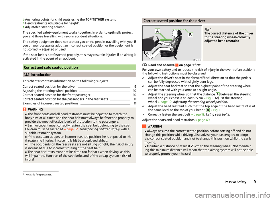
Correct seated position for the driverFig. 1
The correct distance of the driver
to the steering wheel/correctly
adjusted head restraint
Read and observe on page 9 first.
For your own safety and to reduce the risk of injury in the event of an accident, the following instructions must be observed.
Adjust the driver’s seat in the forward/back direction so that the pedals
can be fully depressed with slightly bent legs.
Adjust the seat backrest so that the highest point of the steering wheel
can be reached with your arms at a slight angle.
Adjust the steering wheel so that the distance
A
between the steering
wheel and your chest is at least 25 cm » Fig. 1. Adjust the steering
wheel » page 10 , Adjusting the steering wheel position .
Adjust the head restraint such that the top edge of the head restraint is at
the same level as the top of your head 1)
B
» Fig. 1 .
Correctly fasten the seat belt » page 12, Using seat belts .
Adjust the seats and head restraints » page 69.
WARNING■
Always assume the correct seated position before setting off and do not
change this position while driving. Also advise your passengers to adopt
the correct seated position and not to change this position while the car is
moving.■
Maintain a distance of at least 25 cm to the steering wheel. Not maintain-
ing this minimum distance will mean that the airbag system will not be able
to properly protect you – hazard!
1)
Not valid for sports seat.
9Passive Safety
Page 13 of 204
WARNING (Continued)■When driving, hold the steering wheel with both hands firmly on the out-
er edge in the “9 o'clock” and “3 o'clock” position. Never hold the steering
wheel in the “12 o'clock” position or in any other way (e.g. in the middle or
inner edge of the steering wheel). In such cases, you could severely injure
the arms, hands and head when the driver airbag is deployed.■
Ensure that there are no objects in the driver's footwell as they may get
caught behind the pedals when driving or applying the braking. You would
then no longer be able to operate the clutch, brake or acceleration pedals.
Adjusting the steering wheel position
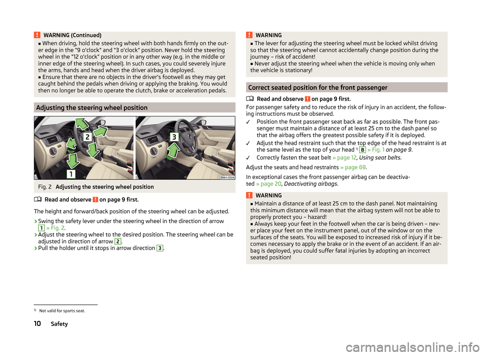
Fig. 2
Adjusting the steering wheel position
Read and observe
on page 9 first.
The height and forward/back position of the steering wheel can be adjusted.
›
Swing the safety lever under the steering wheel in the direction of arrow
1
» Fig. 2 .
›
Adjust the steering wheel to the desired position. The steering wheel can be
adjusted in direction of arrow
2
.
›
Pull the holder until it stops in arrow direction
3
.
WARNING■ The lever for adjusting the steering wheel must be locked whilst driving
so that the steering wheel cannot accidentally change position during the
journey – risk of accident!■
Never adjust the steering wheel when the vehicle is moving only when
the vehicle is stationary!
Correct seated position for the front passenger
Read and observe
on page 9 first.
For passenger safety and to reduce the risk of injury in an accident, the follow-ing instructions must be observed.
Position the front passenger seat back as far as possible. The front pas-
senger must maintain a distance of at least 25 cm to the dash panel so
that the airbag offers the greatest possible safety if it is deployed.
Adjust the head restraint such that the top edge of the head restraint is at
the same level as the top of your head 1)
B
» Fig. 1 on page 9 .
Correctly fasten the seat belt » page 12, Using seat belts .
Adjust the seats and head restraints » page 69.
In exceptional cases the front passenger airbag can be deactiva-
ted » page 20 , Deactivating airbags .
WARNING■
Maintain a distance of at least 25 cm to the dash panel. Not maintaining
this minimum distance will mean that the airbag system will not be able to
properly protect you – hazard!■
Always keep your feet in the footwell when the car is being driven – nev-
er place your feet on the instrument panel, out of the window or on the
surfaces of the seats. You will be exposed to increased risk of injury if it be-
comes necessary to apply the brake or in the event of an accident. If an air-
bag is deployed, you could suffer fatal injuries by adopting an incorrect
seated position!
1)
Not valid for sports seat.
10Safety
Page 16 of 204
WARNING (Continued)■The lock tongue should only be inserted into the lock which is the correct
one for your seat. Wrong use of the safety belt will reduce its capacity to
protect and the risk of injury increases.■
The slot of the belt tongue must not be blocked, otherwise the belt
tongue will not lock in place properly.
■
Many layers of clothing and loose clothing (e. g. a winter coat over a jack-
et) do not allow you to be correctly seated and impairs proper operation of
the seat belts.
■
It is prohibited to use clamps or other objects to adjust seat belts (e. g. for
shortening the belts for smaller persons).
■
The seat belts for the rear seats can only fulfil their function reliably
when the seat backrests are correctly locked into position » page 72.
WARNINGInformation on the care and maintenance of the safety belts■The belt webbing must always be kept clean. Soiled belt webbing may im-
pair proper operation of the inertia reel » page 138.■
The seat belts must not be removed or changed in any way. Do not at-
tempt to repair the seat belts yourself.
■
Check the condition of all the seat belts on a regular basis. If any damage
to the seat belts, seat belt connections, inertia reel or the lock is detected,
the relevant seat belt must be replaced by a specialist garage.
■
Damaged seat belts which have been subjected to stress in an accident
and were therefore stretched, must be replaced – this is best done by a
specialist garage. The anchorage points of the belts must also be inspec-
ted. The anchorage points for the belts should also be checked.
Note
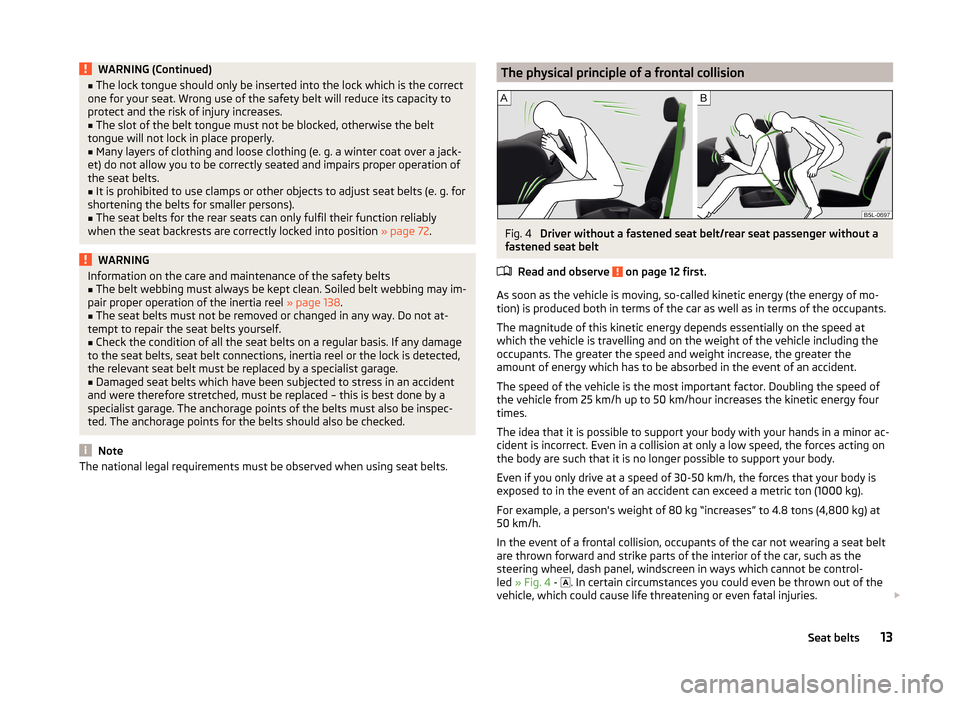
The national legal requirements must be observed when using seat belts.The physical principle of a frontal collisionFig. 4
Driver without a fastened seat belt/rear seat passenger without a
fastened seat belt
Read and observe
on page 12 first.
As soon as the vehicle is moving, so-called kinetic energy (the energy of mo-
tion) is produced both in terms of the car as well as in terms of the occupants.
The magnitude of this kinetic energy depends essentially on the speed at
which the vehicle is travelling and on the weight of the vehicle including the
occupants. The greater the speed and weight increase, the greater the
amount of energy which has to be absorbed in the event of an accident.
The speed of the vehicle is the most important factor. Doubling the speed of
the vehicle from 25 km/h up to 50 km/hour increases the kinetic energy four
times.
The idea that it is possible to support your body with your hands in a minor ac-
cident is incorrect. Even in a collision at only a low speed, the forces acting on
the body are such that it is no longer possible to support your body.
Even if you only drive at a speed of 30-50 km/h, the forces that your body is
exposed to in the event of an accident can exceed a metric ton (1000 kg).
For example, a person's weight of 80 kg “increases” to 4.8 tons (4,800 kg) at 50 km/h.
In the event of a frontal collision, occupants of the car not wearing a seat belt
are thrown forward and strike parts of the interior of the car, such as the
steering wheel, dash panel, windscreen in ways which cannot be control-
led » Fig. 4 -
. In certain circumstances you could even be thrown out of the
vehicle, which could cause life threatening or even fatal injuries.
13Seat belts
Page 19 of 204
Airbag system
Description of the airbag system
Introduction
This chapter contains information on the following subjects:
System description
16
Airbag deployment
16WARNING■ An airbag can only offer you optimal protection in combination with a
fastened seat belt .■
The airbag is not a substitute for the seat belt, but instead forms part of
the complete passive vehicle safety concept.
■
To ensure passengers are protected with the greatest possible effect
when the airbag is deployed, the front seats must be correctly adjusted to
match the body size » page 9, Correct and safe seated position .
■
If you do not fasten the seat belts when driving, lean too far forward or
adopt an incorrect seated position, you are exposing yourself to increased
risk of injury in the event of an accident.
WARNINGInformation on the use of the airbag system■If there is a fault, the airbag system must be checked by a specialist ga-
rage immediately. Otherwise, there is a risk of the airbag not being activa-
ted in the event of an accident.■
No modifications of any kind may be made to parts of the airbag system.
■
Any work on the airbag system, including the installation and removal of
system components due to other repair work (e.g. removal of the steering
wheel), must only be carried out by a specialist garage.
■
Never make any changes to the front bumper or the bodywork.
■
It is prohibited to manipulate individual parts of the airbag system, as this
might result in the airbag being deployed.
■
The protective function of the airbag system is sufficient for only one ac-
cident. The airbag system must then be replaced if the airbag has been de-
ployed.
System description
Read and observe
on page 16 first.
The functional status of the airbag system is indicated by the indicator light
in the instrument cluster » page 39.
When the airbags are deployed, they fill with gas and inflate.
A grey white or red, non-harmful gas is released when the airbag is inflated.
This is perfectly normal and is not an indication of a fire in the vehicle.
Depending on the vehicle equipment, the airbag system consists of the
following modules.
› Electronic control unit.
› Front airbag for the driver and the front passenger
» page 17.
› Side airbags
» page 18.
› Head airbags
» page 19.
› Airbag warning light in the instrument cluster
» page 39.
› Key switch for the front passenger airbag
» page 20.
› Warning light for the front passenger airbag deactivation/activation in the
middle of the dash panel » page 20.
Note
■
The airbag system needs no maintenance during its working life.■If you sell your vehicle, provide the complete vehicle documentation to the
new owner. Please note that the information relating to the possibility of de-
activating the front passenger airbag must be included!■
When disposing of vehicle or parts of the airbag system, it is important to
comply with the national legal requirements.
Airbag deployment
Read and observe
on page 16 first.
The airbags inflate in fractions of a second and at a high speed in order to beable to offer additional protection in the event of an accident.
The airbag system is only functional when the ignition is switched on.
In certain accident situations, the several airbags may be deployed simultane-
ously.
The airbags are not deployed in the case of minor frontal and side collisions,
rear-end collisions, tilting of the vehicle and vehicle rollover.
16Safety
Page 43 of 204
WARNINGWhen a fault in the airbag system occurs, there is a risk of the system not
being triggered in the event of an accident. Therefore, this must be
checked immediately by a specialized company.
Tyre inflation pressure
Read and observe
on page 35 first.
The warning light is illuminated
If the warning light illuminates while driving, it means one of the tyres has
undergone a pressure change.
An audible signal sounds as a warning signal.
›
Immediately reduce speed and avoid sudden steering and braking manoeu-
vres.
›
Stop the vehicle, turn the ignition off and check the tyres and their inflation
pressure » page 153 .
›
Correct the tyre pressure, if necessary or replace the affected
wheel » page 160 or use the repair kit » page 164.
›
Store the tyre pressure values in the system » page 119.
The warning light flashes for about 1 min. and remains illuminated
If the warning light flashes for approximately 1 min. and remains on, there
may be a fault in the tyre pressure monitoring system.
›
Stop the vehicle, turn the ignition off and start the engine again.
If the warning light flashes after starting the engine again, there is a system
error.
Seek help from a specialist garage.
The illumination of the warning light can have the following reasons.
› The vehicle is loaded on one side. Distribute loads as evenly as possible.
› The wheels of one axle are loaded more heavily (e.g. when towing a trailer or
when driving uphill or downhill).
› Snow chains are mounted.
› A wheel has been changed.
Store the tyre pressure values in the system » page 119.
CAUTIONUnder certain circumstances (e.g. sporty style of driving, wintry or unpaved
roads) the warning light in the instrument cluster may be delayed or not
light up at all.
Note
If the vehicle battery has been disconnected and then reconnected, the indica-
tor light comes on after switching on the ignition. If the warning light does
not go out after moving a short distance, this means that there is an error in
the system. Seek help from a specialist garage.
Windscreen washer fluid
Read and observe
on page 35 first.
If the windscreen washer fluid level is too low, the warning light
illumi-
nates .
The following message is shown in the MAXI DOT display. Top up wash fluid!
Top up with liquid » page 143, Windscreen washer system .
Turn signal system
Read and observe
on page 35 first.
Either the left
or the right
warning light flashes depending on the position
of the turn signal lever.
If there is a fault in the turn signal system, the warning light flashes at twice
its normal rate.
Switching off the hazard warning light system is switched on will cause all of
the turn signal lights as well as both warning lights to flash.
Fog lights
Read and observe
on page 35 first.
The warning light
illuminates when the fog lights are operating.
40Using the system
Page 50 of 204
Note■If warning messages are displayed, these messages must be verified to ac-
cess the main menu » page 42, Using the information system .■
If the display is not activated at that moment, the menu always shifts to one
of the higher levels after approx. 10 seconds.
■
Using the factory-fitted radio or navigation system » Radio operating in-
structions or» navigation system operating instructions .
Settings
Read and observe
on page 46 first.
You can change certain settings by means of the MAXI DOT display. The cur-
rent menu item is shown in the top of the display under a line.
The following information can be selected (depending on the equipment in- stalled in the vehicle).
Language
You can set the language for the display texts here.
MFD data
Activate or deactivate certain displays of the multifunction display here.
Time
The time, time format (12 or 24 hour indicator) and the changeover between
summer/winter time can be set here.
Winter tyres
Here, the speed and the switching on and off of the acoustic signals when ex-
ceeding this speed can be adjusted. This function is, for example, used for win-
ter tyres where the maximum permissible speed is lower than the maximum
speed of the vehicle » page 152, Tyres and wheel rims .
As soon as the parking procedure is completed, an audible signal sounds and
the following message appears in the information display.
Winter tyres: maximum ... km/h.
Units
The units for the temperature, consumption and distance driven can be set
here.
Alt. speed dis.
Here, the display of the second speed in mph 1)
can be activated.
Further information » page 33, Display of the second speed .
Service
The days and kilometres remaining until the next service can be displayed
here.
Factory setting
The display functions can be restored to their factory settings here.
Compass point display
Read and observe
on page 46 first.
For vehicles with a factory fitted navigation system, an abbreviation for eachpoint of the compass (depending on the current direction of travel) is shown
on the top left-hand corner of the display.
The compass point display only operates when the ignition is switched on.
Service interval display
Introduction
This chapter contains information on the following subjects:
Prompt in the MAXI DOT display
48
Prompt in the segment display
48
Resetting the service interval display
49
The service interval display shows the time and mileage to the next service
event.
The service due date is automatically displayed on the display and this infor-
mation can be displayed manually if necessary.
The kilometre indicator or the days indicator reduces in steps of 100 km or,
where applicable, days until the service due date is reached.
The information regarding the service intervals can be found in the service
schedule.
1)
For models with the speedometer in mph, the second speed is displayed in km/h.
47Information system
Page 101 of 204
Dial number
Any telephone number can be entered in the Dial number menu item. The re-
quired numbers must be selected one after the other using adjustment wheel
and confirmed by pressing the adjustment wheel. You can select digits 0-9,
symbols
,
, # and the Cancel, Call and Delete functions.
Call register
The following menu items can be selected in the Call register menu item.
■ Missed calls
■ Dialled numbers
■ Received calls
Voice mailbox
In the Voice mailbox menu item, you can set the number of the voice mailbox 1)
and then dial the number.
Bluetooth
The following menu items can be selected from the Bluetooth menu item.
■ User - Overview of the stored telephones
■ New user - Search for new mobile phones that are in the reception range
■ Visibility - Switches on the visibility of the hands-free system for other devi-
ces
■ Media player - Playback via Bluetooth ®
■ Active device - Connected device
■ Paired devices - List of paired devices
■ Find - Device search
■ Phone name - option to change the name of the phone (default SKODA_BT)
Settings
The following menu items can be selected from the Settings menu item.
■ Phone book - Phonebook
■ Update - Update of the phone book 1)
■ List - Arrange the entries in the phone book
■ Surname - Arrange according to surname
■ Surname - Sort by contact name
■ Ring tone - Ring tone setting
Back
Return in the Start menu of the telephone.Voice control
Introduction
This chapter contains information on the following subjects:
Dialogue
98
Voice commands
99
Dialogue
Fig. 96
Multifunction steering wheel:
Voice control
The period of time during which the system is ready to receive voice com-
mands and to carry them out is called "dialogue". The system gives audible
feedback and guides you through the relevant functions if necessary.
Optimum understanding of the voice commands depends on several factors. › Speak at a normal volume without intonation or excessive pauses.
› Avoid poor pronunciation.
› Close the doors, windows and sliding roof in order to reduce or eliminate dis-
turbing noise from outside.
› It is recommended to speak louder at higher speeds, so that your voice is
louder than the increased surrounding noise.
› During the dialogue, limit background noise in the vehicle, e.g. passengers
talking at the same time.
› Do not speak when the system is making an announcement.
The microphone for voice control is housed in the moulded headliner and di-
rected towards the driver and front passenger. Therefore, the driver and the
front passenger can operate the equipment.
1)
On vehicles fitted with the Amundsen+ navigation system, this function can be accessed via the naviga-
tion system menu; refer to the » operating instructions for the Amundsen+ navigation system .
98Using the system
Page 103 of 204
Music playback via Bluetooth®
The universal telephone pre-installation GSM II makes it possible to play back
music via Bluetooth ®
from the devices such as MP3 player, mobile phone or
notebook.
To ensure that music can be played via Bluetooth ®
, you must first pair the de-
vice with the hands-free system in the Phone - Bluetooth - Media player
menu.The music playback process is performed on the connected device.
The universal telephone pre-installation GSM II ensures that the music played back via the hands-free system can be controlled with the remote con-
trol » page 99 , Voice commands .
Note
The device being connected must support the Bluetooth ®
A2DP profile; refer
to the operating instructions for the relevant device being connected.
Operating the radio and navigation system on the multifunction steering wheel
Fig. 97
Multifunction steering wheel: Navigation control buttons
The multifunction steering wheel features buttons for operating the basic
functions for the factory-fitted radio and navigation system » Fig. 97.
The radio and the navigation system can of course still be operated via the de-
vices. A description is included in the relevant operating instructions.
If the side lights are switched on, the buttons on the multifunction steering wheel are illuminated.
The buttons apply for the respective operating mode of the current radio, au-
dio, video or navigation system.
The following functions can be completed by pressing or turning the buttons.Button / adjust- ment
wheel » Fig. 97ActionRadioAudio sourcesNavigation
1PressChange audio source2PressSwitch tone off/on (MUTE )Interrupt current navigation an-
nouncement2Turn upwardsIncrease volume2Turn downwardsDecrease volume3Press brieflySkip to next channelSkip to next trackwithout functionInterrupt traffic report3Press and hold buttonwithout functionFast forwardwithout function4Press brieflySwitch to previous channelChange to start of track a)without functionInterrupt traffic report4Press and hold buttonwithout functionFast rewindwithout function
100Using the system
Page 104 of 204
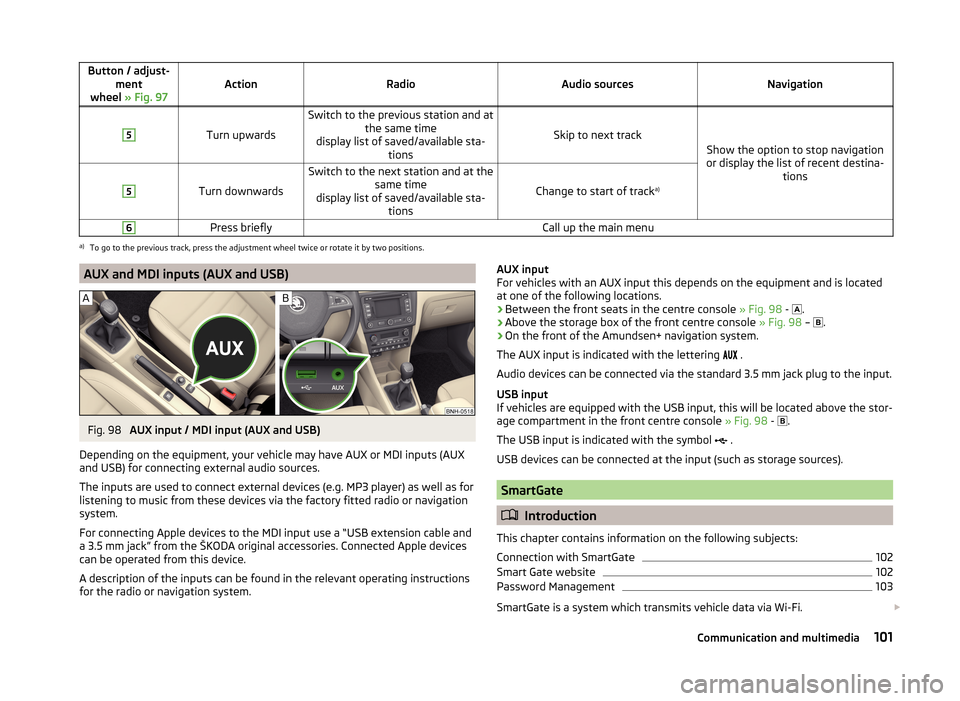
Button / adjust-ment
wheel » Fig. 97ActionRadioAudio sourcesNavigation
5
Turn upwards
Switch to the previous station and at
the same time
display list of saved/available sta- tions
Skip to next track
Show the option to stop navigation
or display the list of recent destina- tions
5
Turn downwards
Switch to the next station and at thesame time
display list of saved/available sta- tions
Change to start of track a)
6Press brieflyCall up the main menua)
To go to the previous track, press the adjustment wheel twice or rotate it by two positions.
AUX and MDI inputs (AUX and USB)Fig. 98
AUX input / MDI input (AUX and USB)
Depending on the equipment, your vehicle may have AUX or MDI inputs (AUX and USB) for connecting external audio sources.
The inputs are used to connect external devices (e.g. MP3 player) as well as for
listening to music from these devices via the factory fitted radio or navigation
system.
For connecting Apple devices to the MDI input use a “USB extension cable and
a 3.5 mm jack” from the ŠKODA original accessories. Connected Apple devices
can be operated from this device.
A description of the inputs can be found in the relevant operating instructions
for the radio or navigation system.
AUX input
For vehicles with an AUX input this depends on the equipment and is located
at one of the following locations.
› Between the front seats in the centre console
» Fig. 98 -
.
› Above the storage box of the front centre console
» Fig. 98 –
.
› On the front of the Amundsen+ navigation system.
The AUX input is indicated with the lettering
.
Audio devices can be connected via the standard 3.5 mm jack plug to the input.
USB input
If vehicles are equipped with the USB input, this will be located above the stor-
age compartment in the front centre console » Fig. 98 -
.
The USB input is indicated with the symbol .
USB devices can be connected at the input (such as storage sources).
SmartGate
Introduction
This chapter contains information on the following subjects:
Connection with SmartGate
102
Smart Gate website
102
Password Management
103
SmartGate is a system which transmits vehicle data via Wi-Fi.
101Communication and multimedia
Page 112 of 204
CAUTION■If the selector lever is moved to mode N while driving, the accelerator pedal
must be released and you will need to wait until the engine has reached its
idling speed before moving the selector lever to a forward driving mode again.■
When the outdoor temperature is below -10 ° C, the selector lever, when
starting, must always be in P mode.
■
When stopping on a slope, never try to keep the vehicle in position by using
the accelerator pedal – this may lead to gear damage.
Note
After the ignition is switched off, the ignition key can only be withdrawn if the
selector lever is in the position P.
Modes and use of selector lever
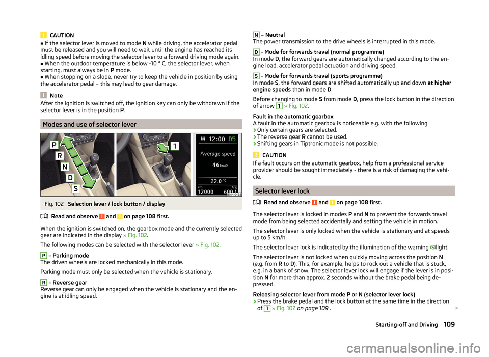
Fig. 102
Selection lever / lock button / display
Read and observe
and on page 108 first.
When the ignition is switched on, the gearbox mode and the currently selected
gear are indicated in the display » Fig. 102.
The following modes can be selected with the selector lever » Fig. 102.
P
– Parking mode
The driven wheels are locked mechanically in this mode.
Parking mode must only be selected when the vehicle is stationary.
R
– Reverse gear
Reverse gear can only be engaged when the vehicle is stationary and the en-
gine is at idling speed.
N – Neutral
The power transmission to the drive wheels is interrupted in this mode.D
- Mode for forwards travel (normal programme)
In mode D, the forward gears are automatically changed according to the en-
gine load, accelerator pedal actuation and driving speed.
S
- Mode for forwards travel (sports programme)
In mode S, the forward gears are shifted automatically up and down at higher
engine speeds than in mode D.
Before changing to mode S from mode D, press the lock button in the direction
of arrow
1
» Fig. 102 .
Fault in the automatic gearbox
A fault in the automatic gearbox is noticeable e.g. with the following.
› Only certain gears are selected.
› The reverse gear
R cannot be used.
› Shifting gears in Tiptronic mode is not possible.
CAUTION
If a fault occurs on the automatic gearbox, help from a professional service
provider should be sought immediately - there is a risk of damaging the vehi-
cle.
Selector lever lock
Read and observe
and on page 108 first.
The selector lever is locked in modes P and N to prevent the forwards travel
mode from being selected accidentally and setting the vehicle in motion.
The selector lever is only locked when the vehicle is stationary and at speeds
up to 5 km/h.
The selector lever lock is indicated by the illumination of the warning light.
The selector lever is not locked when quickly moving across the position N
(e.g. from R to D). This, for example, helps to rock out a vehicle that is stuck,
e.g. in a bank of snow. The selector lever lock will engage if the lever is in posi-
tion N for more than approx. 2 seconds without the brake pedal being de-
pressed.
Releasing selector lever from mode P or N (selector lever lock)
›
Press the brake pedal and the lock button at the same time in the direction
of
1
» Fig. 102 on page 109 .
109Starting-off and Driving