check engine light SKODA RAPID SPACEBACK 2014 1.G User Guide
[x] Cancel search | Manufacturer: SKODA, Model Year: 2014, Model line: RAPID SPACEBACK, Model: SKODA RAPID SPACEBACK 2014 1.GPages: 204, PDF Size: 27.11 MB
Page 96 of 204
If you select a temperature higher than +29 ℃, “HI” appears in the display.
At both end positions, Climatronic runs at maximum cooling/heating output
and the temperature is automatically not regulated.
Controlling blower
The Climatronic system controls the blower stages automatically in line with the interior temperature. However, the blower level can be manually adjusted
to suit your particular needs.
If the blower speed is reduced to a minimum, Climatronic is switched off.
The blower speed set is indicated by displaying the corresponding number of
segments (pos. 9
» Fig. 94 ) in the display.
Automatic mode
The automatic mode is used in order to maintain a constant temperature and
to demist the windows in the interior of the car.
To switch on press the
button. The display shows
(pos.
4
» Fig. 94 ).
Automatic mode can be switched off by pressing one of the buttons for the air
distribution or by increasing/decreasing the blower speed. The temperature is
nevertheless regulated.
WARNING■ Do not switch off the Climatronic system for longer than necessary.■Switch on the Climatronic system as soon as the windows mist up.
Note
■Do not stick anything on or cover the interior temperature sensor11 » Fig. 94 ; it could have an unfavourable effect on the Climatronic system.■
During operation of the Climatronic, an increase in engine idle speed can oc-
cur under certain circumstances in order to ensure adequate heating comfort.
■
As soon as the windscreen mists up, press the symbol button
. Press the
button once the windscreen has demisted.
Efficient handling of the cooling system
Read and observe
and on page 89 first.
The air conditioning system compressor uses power from the engine when in
cooling mode, which will affect the fuel consumption.
It recommended to open the windows or the doors of a vehicle for which the
interior has been strongly heated through the effect of direct sunlight in order
to allow the heated air to escape.
The cooling system should not be on if the windows are open.
For the sake of the environment
Pollutant emissions are also reduced when fuel is saved » page 111.
malfunctions
Read and observe
and on page 89 first.
If the cooling system does not operate at outside temperatures higher than +5
°C, there is a problem in the system. The reasons for this may be.
› One of the fuses has blown. Check the fuse and replace if necessa-
ry » page 173 .
› The cooling system has switched off automatically for a short time because
the coolant temperature of the engine is too hot » page 32.
If you are not able to resolve the operational problem yourself, or if the cooler
output has reduced, switch off the cooling system and seek assistance from a
specialist garage.
93Heating and air conditioning
Page 109 of 204
CAUTIONDo not switch the engine off immediately at the end of your journey after the
engine has been operated over a prolonged period at high loads but leave it to
run at an idling speed for about 1 minute. This prevents any possible accumula-
tion of heat when the engine is switched off.
Note
After switching off the ignition, the radiator fan may intermittently continue to
operate for approx. 10 minutes.
Brakes and parking
Introduction
This chapter contains information on the following subjects:
Information on braking
106
Handbrake
107
Parking
107WARNING■ Greater physical effort is required for braking when the engine is switch-
ed off – risk of accident!■
The clutch pedal must be actuated when braking on a vehicle with man-
ual transmission, when the vehicle is in gear and at low revs. Otherwise,
the functionality of the brake system may be impaired – risk of accident!
■
When leaving the vehicle, never leave persons who might, for example,
release the handbrake or take the vehicle out of gear unattended in the ve-
hicle. The vehicle could then start to move – risk of accident!
■
Observe the recommendations on the new brake pads » page 111, New
brake pads .
CAUTION
Never let the brakes slip with light pressure on the pedal if braking is not nec-
essary. This causes the brakes to overheat and can also result in a longer brak-
ing distance and excessive wear.Information on braking
Read and observe
and on page 106 first.
Wear-and-tear
The wear of the brake pads is dependent on the operating conditions and driv-
ing style.
The brake pads wear more quickly if a lot of journeys are completed in towns
and over short distances or if a very sporty style of driving is adopted.
Under these severe conditions , the thickness of the brake pads must also be
checked by a specialist garage between service intervals.
Wet roads or road salt
The performance of the brakes can be delayed as the brake discs and brake
pads may be moist or have a coating of ice or layer of salt on them in winter.
The brakes are cleaned and dried by applying the brakes several times »
.
Corrosion
Corrosion on the brake discs and dirt on the bake pads occur if the vehicle has
been parked for a long period and if you do not make much use of the braking
system. The brakes are cleaned by applying the brakes several times »
.
Long or steep slopes
Before travelling a long distance with a steep gradient, reduce speed and shift
into the next lowest gear. As a result, the braking effect of the engine will be
used, reducing the load on the brakes. Any additional braking should be com-
pleted intermittently, not continuously.
Emergency brake display
If the brakes are applied in full and the control unit for the braking system con-
siders the situation to be dangerous for the following traffic, the brake light
flashes automatically.
After the speed was reduced below around 10 km/h or the vehicle was stop-
ped, the brake light stops flashing and the hazard warning light system
switches on. The hazard warning light system is switched off automatically af- ter accelerating or driving off again.
Faults in the brake surface
If it is found that the braking distance has suddenly become longer and that
the brake pedal can be depressed further, the brake system may be faulty.
Visit a specialist garage immediately and adjust your style of driving appropri-
ately, as you will not know the exact extent of the damage.
106Driving
Page 147 of 204
The cleaning fluid is provided for the cleaning of the front and rear window as
well as the headlight.
The capacity of the reservoir is about 3.5 litres or about 5.4 litres on vehicles
that have a headlight cleaning system 1)
.
Clear water is not sufficient to intensively clean the windscreen and head-
lights. We recommend using clean water together with a screen cleaner from
the range of ŠKODA Original Accessories (with anti-freeze in winter), which
will remove any stubborn dirt.
In Winter, the washing water should always be mixed with anti-freeze even if
the vehicle has heated windscreen washer nozzles.
Under exceptional circumstances, methylated spirits can also be used if no
screen cleaner with anti-freeze is available. The concentration of methylated
spirits must not be more than 15 %. The anti-freeze protection at this concen-
tration is sufficient only to -5 °C.
CAUTION
■ Under no circumstances must radiator anti-freeze or other additives be add-
ed to the windscreen washer fluid.■
If the vehicle is fitted with a headlight cleaning system, only cleaning prod-
ucts which do not attack the polycarbonate coating of the headlights must be
added to the windscreen washer fluid.
■
Do not remove the filter from the windscreen washer fluid reservoir when re-
filling, as this may cause contamination of the liquid transportation system,
leading in turn to a windscreen washer system malfunction.
Engine oil
Introduction
This chapter contains information on the following subjects:
Specification
144
Checking the oil level
145
Replenishing
146
The engine has been factory-filled with a high-grade oil that can be use
throughout the year - except in extreme climate zones.
The engine oils are undergoing continuous further development. Thus the in- formation stated in this Owner's Manual is only correct at the time of publica-
tion.
ŠKODA Service Partners are informed about the latest changes by the manu-
facturer. We therefore recommend that the oil change be completed by a
ŠKODA Service Partner.
The specifications (VW standards) stated in the following can be indicated sep-
arately or together with other specifications on the bottle.
The engine oil should be changed after specified service intervals » page 47.WARNINGThe engine compartment of your car is a hazardous area. The following
warning instructions must be followed at all times when working in the en-
gine compartment » page 141.
CAUTION
Do not pour any additives into the engine oil – risk of serious damage to the
engine parts!
Note
■ Before a long drive we recommend that you purchase and carry with you en-
gine oil which complies with the specification for your vehicle.■
We recommend that you use oils from ŠKODA Original Accessories.
■
If your skin has come into contact with oil, it must be washed thoroughly.
Specification
Read and observe
and on page 144 first.
Vehicles with variable service intervals
Petrol enginesSpecification1.2 litres/55 kWVW 503 00, VW 504 001.2 l/63 kW TSIVW 504 001.2 l/77 kW TSIVW 504 001.4 l/90 kW TSIVW 503 00, VW 504 00 1)
In some countries, 5.4 l. applies for both variants.
144General Maintenance
Page 148 of 204
Diesel enginea)Specification1.6 l/66, 77 kW TDI CRVW 507 00a)
Engine oil VW 505 01 can optionally be used in diesel engines
without a DPF.
Vehicles with fixed service intervals
Petrol enginesSpecification1.2 litres/55 kWVW 501 01, VW 502 001.2 l/63 kW TSIVW 502 001.2 l/77 kW TSIVW 502 001.4 l/90 kW TSIVW 501 01, VW 502 001.6 litres/77 kWVW 501 01, VW 502 00Diesel engine a)Specification1.6 l/66, 77 kW TDI CRVW 507 00a)
Engine oil VW 505 01 can optionally be used in diesel engines
without a DPF.
CAUTION
■
If the above engine oils are not available, a different engine oil can be used in
an emergency. To prevent damage to the engine, a maximum of 0.5 litres only
of the following engine oils may be used: ■ For petrol engine models: ACEA A3/ACEA B4 or API SN, (API SM);
■ for diesel engine models: ACEA C3 or API CJ-4.
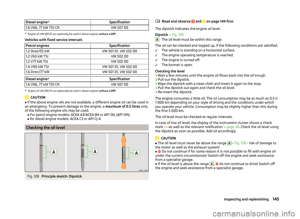
Checking the oil level
Fig. 128
Principle sketch: Dipstick
Read and observe and on page 144 first.
The dipstick indicates the engine oil level .
Dipstick » Fig. 128
The oil level must be within this range.
The oil can be checked and topped up, if the following conditions are satisfied. The vehicle is standing on a horizontal surface.
The engine operating temperature is reached.
The engine is turned off.
The bonnet is open.
Checking the level
›
Wait a few minutes until the engine oil flows back into the oil trough.
›
Pull out the dipstick.
›
Wipe the dipstick with a clean cloth and insert it again to the stop.
›
Pull the dipstick out again and check the oil level.
›
Re-insert the dipstick.
The engine consumes a little oil. The oil consumption may be as much as 0.5 l/
1 000 km depending on your style of driving and the conditions under which
you operate your vehicle. Consumption may be slightly higher than this during
the first 5 000 km.
The oil level must be checked at regular intervals.
In case of low oil level, the display of the instrument cluster shows a check
mark as well as the relevant notification
» page 36. Check the oil level using
the dipstick as soon as possible. Add oil accordingly.
CAUTION
■ The oil level must never be above the range A» Fig. 128 - risk of damage to
the motor as well as the exhaust system!■
Do not continue if for some reason it is not possible to fill with engine oil
under the current circumstances! Switch off the engine and seek assistance
from a specialist garage.
■
If the oil level is above the range
A
,
do not continue to drive! Switch off
the engine and seek assistance from a specialist garage.
A145Inspecting and replenishing
Page 149 of 204

ReplenishingRead and observe
and on page 144 first.
›
Unscrew the cap of the engine oil filler opening » Fig. 126 on page 143 .
›
Replenish the oil in portions of 0.5 litres in accordance with the correct speci-
fications » page 144 .
›
Check the oil level » page 145.
›
Screw the lid of the engine oil filler closed carefully.
›
Pull the dipstick out as far as the stop.
Coolant
Introduction
This chapter contains information on the following subjects:
Checking the coolant level
147
Replenishing
147
The coolant provides cooling for the motor.
It consists of water and coolant additive with additives that protect the cooling
system against corrosion and prevents furring.
The coolant additive level in the coolant must be at least 40%.
The coolant additive may be increased to a maximum of 60%.
The correct mixing ratio of water and coolant additive is to be checked if nec- essary by a specialist garage or is to be restored if necessary.
The description of the coolant is shown in the coolant expansion reser-
voir » Fig. 129 on page 147 .
WARNINGThe engine compartment of your car is a hazardous area. The following
warning instructions must be followed at all times when working in the en- gine compartment » page 141.■
The coolant is harmful to health.
■
Avoid contact with the coolant.
■
Coolant vapours are harmful to health.
■
Never open the end cover of the coolant expansion reservoir while the
engine is still warm. The cooling system is pressurised!
WARNING (Continued)■ When opening the end cover of the coolant expansion reservoir, cover it
with a cloth to protect your face, hands and arms from hot steam or hot
coolant.■
If any coolant splashes into your eyes, immediately rinse out your eyes
with clear water and contact a doctor as soon as possible.
■
Always keep the coolant in the original container, safe from people who
are not completely independent, especially children - there is a danger of
poisoning!
■
If coolant is swallowed, consult a doctor immediately.
■
Never spill operating fluids over the hot engine - risk of fire.
CAUTION
■ Do not continue if for some reason it is not possible to fill with coolant un-
der the current circumstances! Switch off the engine and seek assistance from
a specialist garage.■
If the expansion tank is empty, do not top up with coolant. The system could
ventilate - there is a risk of engine damage,
not continue! Switch off the en-
gine and seek assistance from a specialist garage.
■
The concentration of coolant additive in the coolant must never be under
40%.
■
Over 60% of coolant additive in the coolant reduces the antifreeze protec-
tion and cooling effect.
■
A coolant additive that does not comply with the correct specification can
significantly reduce the corrosion protection of the cooling system.
■
Any faults resulting from corrosion may cause a loss of coolant and can con-
sequently result in major engine damage!
■
Do not fill the coolant above the mark
A
. » Fig. 129 on page 147
■
If an error occurs, leading to the engine overheating, the help of a professio-
nal garage is to be sought - there is a risk of serious engine damage occurring.
■
Additional headlights and other attached components in front of the air inlet
impair the cooling efficiency of the coolant.
■
Never cover the radiator - there is a risk of the engine overheating.
146General Maintenance
Page 150 of 204
Checking the coolant levelFig. 129
Coolant expansion reservoir
Read and observe and on page 146 first.
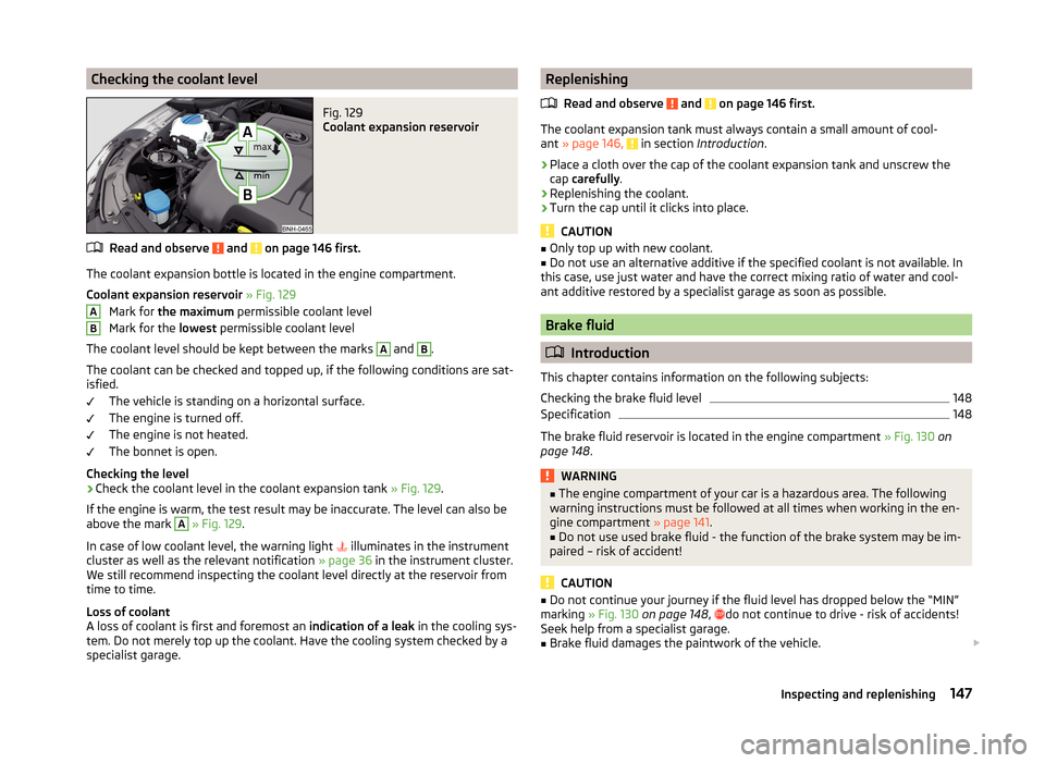
The coolant expansion bottle is located in the engine compartment.
Coolant expansion reservoir » Fig. 129
Mark for the maximum permissible coolant level
Mark for the lowest permissible coolant level
The coolant level should be kept between the marks
A
and
B
.
The coolant can be checked and topped up, if the following conditions are sat-
isfied.
The vehicle is standing on a horizontal surface.
The engine is turned off.
The engine is not heated.
The bonnet is open.
Checking the level
›
Check the coolant level in the coolant expansion tank » Fig. 129.
If the engine is warm, the test result may be inaccurate. The level can also be
above the mark
A
» Fig. 129 .
In case of low coolant level, the warning light illuminates in the instrument
cluster as well as the relevant notification » page 36 in the instrument cluster.
We still recommend inspecting the coolant level directly at the reservoir from
time to time.
Loss of coolant
A loss of coolant is first and foremost an indication of a leak in the cooling sys-
tem. Do not merely top up the coolant. Have the cooling system checked by a
specialist garage.
ABReplenishing
Read and observe
and on page 146 first.
The coolant expansion tank must always contain a small amount of cool-
ant » page 146, in section Introduction .
›
Place a cloth over the cap of the coolant expansion tank and unscrew the
cap carefully .
›
Replenishing the coolant.
›
Turn the cap until it clicks into place.
CAUTION
■
Only top up with new coolant.■Do not use an alternative additive if the specified coolant is not available. In
this case, use just water and have the correct mixing ratio of water and cool-
ant additive restored by a specialist garage as soon as possible.
Brake fluid
Introduction
This chapter contains information on the following subjects:
Checking the brake fluid level
148
Specification
148
The brake fluid reservoir is located in the engine compartment » Fig. 130 on
page 148 .
WARNING■
The engine compartment of your car is a hazardous area. The following
warning instructions must be followed at all times when working in the en-
gine compartment » page 141.■
Do not use used brake fluid - the function of the brake system may be im-
paired – risk of accident!
CAUTION
■ Do not continue your journey if the fluid level has dropped below the “MIN”
marking » Fig. 130 on page 148 , do not continue to drive - risk of accidents!
Seek help from a specialist garage.■
Brake fluid damages the paintwork of the vehicle.
147Inspecting and replenishing
Page 151 of 204
Note■The brake fluid is changed as part of a compulsory inspection service.■We recommend using brake fluids from the ŠKODA Original Accessories
range.
Checking the brake fluid level
Fig. 130
Brake fluid reservoir
Read and observe and on page 147 first.
The fluid can be checked if the following conditions are met.
The vehicle is standing on a horizontal surface.
The engine is turned off.
The bonnet is open.
Checking the level
›
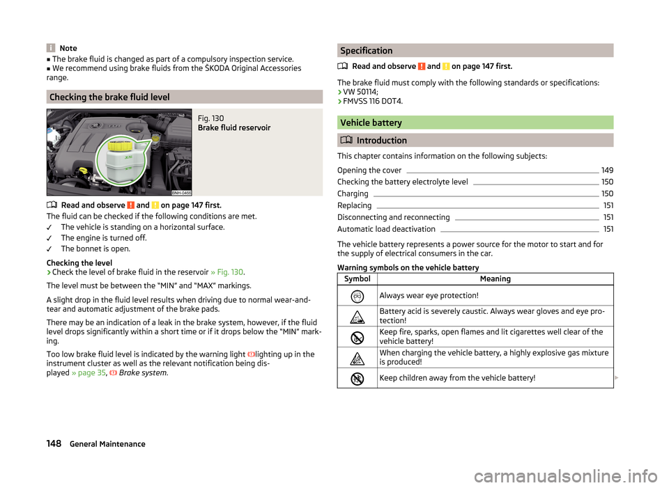
Check the level of brake fluid in the reservoir » Fig. 130.
The level must be between the “MIN” and “MAX” markings.
A slight drop in the fluid level results when driving due to normal wear-and-
tear and automatic adjustment of the brake pads.
There may be an indication of a leak in the brake system, however, if the fluid
level drops significantly within a short time or if it drops below the “MIN” mark-
ing.
Too low brake fluid level is indicated by the warning light
lighting up in the
instrument cluster as well as the relevant notification being dis-
played » page 35 ,
Brake system .
Specification
Read and observe
and on page 147 first.
The brake fluid must comply with the following standards or specifications:› VW 50114;
› FMVSS 116 DOT4.
Vehicle battery
Introduction
This chapter contains information on the following subjects:
Opening the cover
149
Checking the battery electrolyte level
150
Charging
150
Replacing
151
Disconnecting and reconnecting
151
Automatic load deactivation
151
The vehicle battery represents a power source for the motor to start and for
the supply of electrical consumers in the car.
Warning symbols on the vehicle battery
SymbolMeaningAlways wear eye protection!Battery acid is severely caustic. Always wear gloves and eye pro-
tection!Keep fire, sparks, open flames and lit cigarettes well clear of the
vehicle battery!When charging the vehicle battery, a highly explosive gas mixture
is produced!Keep children away from the vehicle battery! 148General Maintenance
Page 153 of 204
Checking the battery electrolyte levelFig. 132
Electrolyte level indicator
Read and observe and on page 149 first.
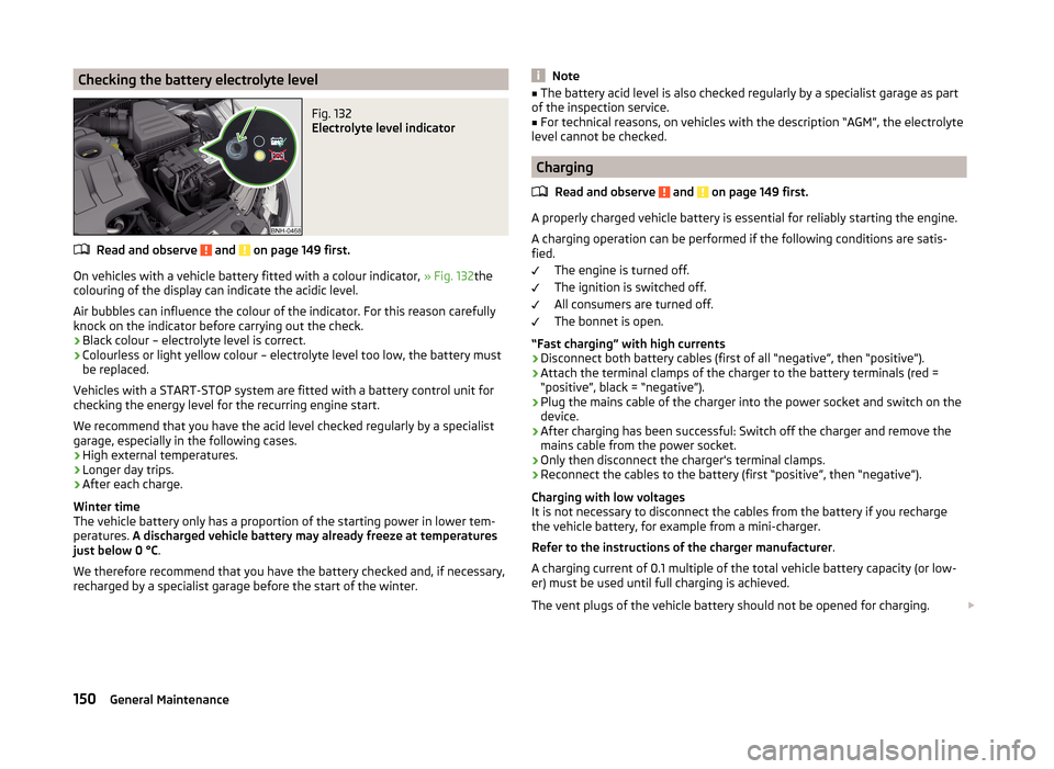
On vehicles with a vehicle battery fitted with a colour indicator, » Fig. 132the
colouring of the display can indicate the acidic level.
Air bubbles can influence the colour of the indicator. For this reason carefully knock on the indicator before carrying out the check.
› Black colour – electrolyte level is correct.
› Colourless or light yellow colour – electrolyte level too low, the battery must
be replaced.
Vehicles with a START-STOP system are fitted with a battery control unit for
checking the energy level for the recurring engine start.
We recommend that you have the acid level checked regularly by a specialist garage, especially in the following cases.
› High external temperatures.
› Longer day trips.
› After each charge.
Winter time
The vehicle battery only has a proportion of the starting power in lower tem-
peratures. A discharged vehicle battery may already freeze at temperatures
just below 0 °C .
We therefore recommend that you have the battery checked and, if necessary,
recharged by a specialist garage before the start of the winter.
Note■ The battery acid level is also checked regularly by a specialist garage as part
of the inspection service.■
For technical reasons, on vehicles with the description “AGM”, the electrolyte
level cannot be checked.
Charging
Read and observe
and on page 149 first.
A properly charged vehicle battery is essential for reliably starting the engine.A charging operation can be performed if the following conditions are satis-
fied.
The engine is turned off.
The ignition is switched off.
All consumers are turned off.
The bonnet is open.
“Fast charging” with high currents
›
Disconnect both battery cables (first of all “negative”, then “positive”).
›
Attach the terminal clamps of the charger to the battery terminals (red =
“positive”, black = “negative”).
›
Plug the mains cable of the charger into the power socket and switch on the
device.
›
After charging has been successful: Switch off the charger and remove the
mains cable from the power socket.
›
Only then disconnect the charger's terminal clamps.
›
Reconnect the cables to the battery (first “positive”, then “negative”).
Charging with low voltages
It is not necessary to disconnect the cables from the battery if you recharge
the vehicle battery, for example from a mini-charger.
Refer to the instructions of the charger manufacturer .
A charging current of 0.1 multiple of the total vehicle battery capacity (or low-
er) must be used until full charging is achieved.
The vent plugs of the vehicle battery should not be opened for charging.
150General Maintenance
Page 168 of 204

Components of the puncture repair kitsFig. 145
Principle sketch: Components of the breakdown kit
Read and observe
on page 164 first.
Components of the set » Fig. 145
Sticker with speed designation “max. 80 km/h”/“max. 50 mph”
Valve remover
Inflation hose with plug
Air compressor
Button for releasing the tyre pressure
12 volt cable connector
Tyre inflation hose
Tyre inflation pressure indicator
ON and OFF switch
Tyre inflater bottle with sealing agent
Replacement valve core
The valve remover
2
has a slot at its lower end which fits into the valve core.
The kit is located in a box under the floor covering in the luggage compart-
ment. This contains a sealing means and an air compressor.
Note
The declaration of conformity is included with the air compressor or the log
folder.1234567891011General information
Read and observe
on page 164 first.
For your own safety and the safety of your passengers, the following instruc-
tions must be observed before carrying out a wheel repair on the road.
Switch on the hazard warning lights system.
The warning triangle is to be set up at the prescribed distance - observe
the national legal provisions when doing so.
Park the vehicle as far away as possible from the flow of traffic.
Choose a location with a flat, solid surface.
Have all the occupants get out. The passengers should not stand on the
road (instead they should remain behind a crash barrier, for instance) while
the wheel is being changed.
The national legal requirements must be observed when repairing a tyre.
The breakdown kit must not be used under the following circumstances. › The rim is damaged.
› The outside temperature is below -20 ° C.
› The cut or puncture is larger than 4 mm.
› The tyre wall is damaged.
› The result will be to drive with very low tyre pressure or with a completely
flat tyres.
› After the expiration date (see inflation bottle).
Preparations for using the breakdown kit
Read and observe
on page 164 first.
The following preparatory work must be carried out before using the puncturerepair kit.
›
Switch off the engine.
›
Select the first gear or move the selector lever for the automatic gearbox
into position P .
›
Firmly apply the handbrake.
›
Check that you can carry out the repairs with the breakdown kit » page 165,
General information .
›
Remove the breakdown kit from the boot.
›
Stick the sticker
1
» Fig. 145 on page 165 on the dashboard in the driver's
field of view.
›
Unscrew the valve cap.
165Emergency equipment and self-help
Page 179 of 204

Replacing bulbs
Introduction
This chapter contains information on the following subjects:
Bulb arrangement in the headlights
176
Replacing the high beam bulb (halogen headlights)
177
Replacing bulb for main beam, daytime running lights and parking light
177
Changing the front turn signal bulb
178
Replacing the bulb for the fog light
178
Replacing the bulb for the licence plate light
179
Rear Light
179
Replacing bulbs in rear light
180
Some manual skills are required to change a bulb. For this reason, we recom-
mend having bulbs replaced by a specialist garage or seeking other expert help
in the event of any uncertainties.
› Switch off the ignition and all of the lights before replacing a bulb.
› Faulty bulbs must only be replaced with the same type of bulbs. The designa-
tion is located on the light socket or the glass bulb.
› A stowage compartment for replacement bulbs is located in a plastic box in
the spare wheel or underneath the floor covering in the boot.
WARNING■ Always read and observe the warning notes before completing any work
in the engine compartment » page 141.■
Accidents can be caused if the road in front of the vehicle is not suffi-
ciently illuminated and the vehicle cannot be seen or can only be seen with
difficulty by other road users.
■
H7 and H15 bulbs are pressurised and may burst when changing the bulb -
risk of injury! We therefore recommended wearing gloves and safety
glasses when changing a bulb.
■
Gas discharge bulbs (xenon bulbs) operate with a high voltage, professio-
nal knowledge is required – risk of death!
■
Switch off the respective vehicle light when changing the bulb.
CAUTION
Do not take hold of the glass bulb with naked fingers (even the smallest
amount of dirt reduces the working life of the light bulb). Use a clean cloth,
napkin, or similar.Note■ This Owner's Manual only describes the replacement of bulbs where it is pos-
sible to replace the bulbs on your own without any complications arising. Other
bulbs must be replaced by a specialist garage.■
We recommend that a box of replacement bulbs always be carried in the ve-
hicle. Replacement bulbs can be purchased from ŠKODAOriginal Accessories.
■
We recommend having the headlight settings checked by a specialist garage
after replacing a bulb in the main, low or fog beam.
■
In case of failure of a xenon gas discharge lamp or an LED diode, visit a spe-
cialist garage.
Bulb arrangement in the headlights
Fig. 161
Principle sketch: Headlights
Read and observe and on page 176 first.
Bulb arrangement » Fig. 161
Low beam or low beam with xenon gas discharge lamp
Main beam, separate daytime running lights, and parking light
Turn signal light (at the front)
ABC176Do-it-yourself