navigation system SKODA RAPID SPACEBACK 2014 1.G User Guide
[x] Cancel search | Manufacturer: SKODA, Model Year: 2014, Model line: RAPID SPACEBACK, Model: SKODA RAPID SPACEBACK 2014 1.GPages: 204, PDF Size: 27.11 MB
Page 103 of 204
Music playback via Bluetooth®
The universal telephone pre-installation GSM II makes it possible to play back
music via Bluetooth ®
from the devices such as MP3 player, mobile phone or
notebook.
To ensure that music can be played via Bluetooth ®
, you must first pair the de-
vice with the hands-free system in the Phone - Bluetooth - Media player
menu.The music playback process is performed on the connected device.
The universal telephone pre-installation GSM II ensures that the music played back via the hands-free system can be controlled with the remote con-
trol » page 99 , Voice commands .
Note
The device being connected must support the Bluetooth ®
A2DP profile; refer
to the operating instructions for the relevant device being connected.
Operating the radio and navigation system on the multifunction steering wheel
Fig. 97
Multifunction steering wheel: Navigation control buttons
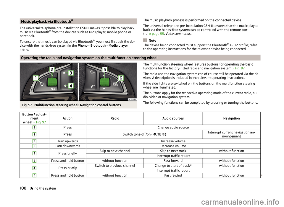
The multifunction steering wheel features buttons for operating the basic
functions for the factory-fitted radio and navigation system » Fig. 97.
The radio and the navigation system can of course still be operated via the de-
vices. A description is included in the relevant operating instructions.
If the side lights are switched on, the buttons on the multifunction steering wheel are illuminated.
The buttons apply for the respective operating mode of the current radio, au-
dio, video or navigation system.
The following functions can be completed by pressing or turning the buttons.Button / adjust- ment
wheel » Fig. 97ActionRadioAudio sourcesNavigation
1PressChange audio source2PressSwitch tone off/on (MUTE )Interrupt current navigation an-
nouncement2Turn upwardsIncrease volume2Turn downwardsDecrease volume3Press brieflySkip to next channelSkip to next trackwithout functionInterrupt traffic report3Press and hold buttonwithout functionFast forwardwithout function4Press brieflySwitch to previous channelChange to start of track a)without functionInterrupt traffic report4Press and hold buttonwithout functionFast rewindwithout function
100Using the system
Page 104 of 204
Button / adjust-ment
wheel » Fig. 97ActionRadioAudio sourcesNavigation
5
Turn upwards
Switch to the previous station and at
the same time
display list of saved/available sta- tions
Skip to next track
Show the option to stop navigation
or display the list of recent destina- tions
5
Turn downwards
Switch to the next station and at thesame time
display list of saved/available sta- tions
Change to start of track a)
6Press brieflyCall up the main menua)
To go to the previous track, press the adjustment wheel twice or rotate it by two positions.
AUX and MDI inputs (AUX and USB)Fig. 98
AUX input / MDI input (AUX and USB)
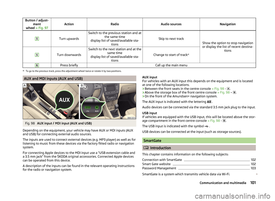
Depending on the equipment, your vehicle may have AUX or MDI inputs (AUX and USB) for connecting external audio sources.
The inputs are used to connect external devices (e.g. MP3 player) as well as for
listening to music from these devices via the factory fitted radio or navigation
system.
For connecting Apple devices to the MDI input use a “USB extension cable and
a 3.5 mm jack” from the ŠKODA original accessories. Connected Apple devices
can be operated from this device.
A description of the inputs can be found in the relevant operating instructions
for the radio or navigation system.
AUX input
For vehicles with an AUX input this depends on the equipment and is located
at one of the following locations.
› Between the front seats in the centre console
» Fig. 98 -
.
› Above the storage box of the front centre console
» Fig. 98 –
.
› On the front of the Amundsen+ navigation system.
The AUX input is indicated with the lettering
.
Audio devices can be connected via the standard 3.5 mm jack plug to the input.
USB input
If vehicles are equipped with the USB input, this will be located above the stor-
age compartment in the front centre console » Fig. 98 -
.
The USB input is indicated with the symbol .
USB devices can be connected at the input (such as storage sources).
SmartGate
Introduction
This chapter contains information on the following subjects:
Connection with SmartGate
102
Smart Gate website
102
Password Management
103
SmartGate is a system which transmits vehicle data via Wi-Fi.
101Communication and multimedia
Page 117 of 204
NoteFor vehicles without stabilization control (ESC), during a TCS intervention the
control indicator blinks in the instrument cluster.
Electronic Differential Lock (EDL)
Read and observe
on page 113 first.
EDL prevents the turning of the respective wheel of the driven axle. EDL
brakes the spinning wheel, if necessary, and transmits the driving force to the
other driving wheel. Driving becomes easier on road surfaces with different
traction under each wheel of the driven axle.
The EDL switches off automatically in order to avoid excessive heat generation
on the brake of the wheel being braked. The vehicle can continue to be driven
and has the same characteristics as a vehicle not fitted with EDL. Once the
brakes have cooled down, there is an automatic re-activation of EDL.
Hydraulic Brake Assist (HBA)
Read and observe
on page 113 first.
The HBA increases the braking effect and helps to reduce the braking dis-
tance.
The HBA is activated by the very quick operation of the brake pedal. In order to
achieve the shortest possible braking distance, the brake pedal must be ap-
plied firmly until the vehicle has come to a standstill.
The HBA function is automatically deactivated when the brake pedal is re-
leased.
Hill Hold Control (HHC)
Read and observe
on page 113 first.
When driving on slopes, HHC allows you to move your foot from the brake ped-al to the accelerator pedal without having to use the handbrake.
The system holds the brake pressure produced by the activation of the brake pedal for approx. 2 seconds after the brake pedal is released.
The brake pressure drops gradually the more you operate the accelerator ped-
al. If the vehicle does not start off within 2 seconds, it starts to roll back.
The HHC is active from a 5% slope if the driver's door is closed. HHC is always
only active on slopes when in forward or reverse start off.
Parking aid
Introduction
This chapter contains information on the following subjects:
Function
115
Activation/deactivation
115
The parking aid (hereinafter referred to only as a system) draws attention via
acoustic signals and an indication in the radio or navigation display when ma-
noeuvring around obstacles in the vicinity of the vehicle.
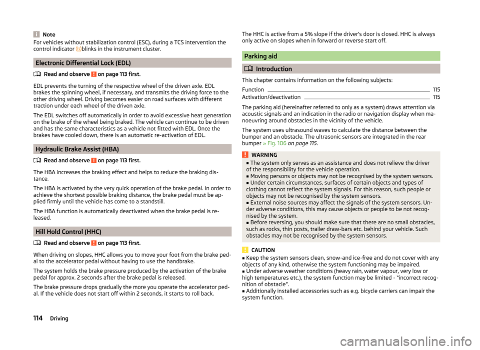
The system uses ultrasound waves to calculate the distance between the
bumper and an obstacle. The ultrasonic sensors are integrated in the rear
bumper » Fig. 106 on page 115 .
WARNING■
The system only serves as an assistance and does not relieve the driver
of the responsibility for the vehicle operation.■
Moving persons or objects may not be recognised by the system sensors.
■
Under certain circumstances, surfaces of certain objects and types of
clothing cannot reflect the system signals. For this reason, such people or
objects may not be recognised by the system sensors.
■
External noise sources may affect the signals of the system sensors. Un-
der adverse conditions, this may cause objects or people to be not recog-
nised by the system.
■
Before reversing, you should make sure that there are no small obstacles,
such as rocks, thin posts, trailer draw-bars etc. behind your vehicle. Such
obstacles may not be recognised by the system sensors.
CAUTION
■ Keep the system sensors clean, snow-and ice-free and do not cover with any
objects of any kind, otherwise the system functioning may be impaired.■
Under adverse weather conditions (heavy rain, water vapour, very low or
high temperatures etc.), the system function may be limited - “incorrect recog-
nition of obstacle”.
■
Additionally installed accessories such as e.g. bicycle carriers can impair the
system function.
114Driving
Page 118 of 204

FunctionFig. 106
Location of the sensors / range of the sensors
Read and observe
and on page 114 first.
Approximate range of sensors
Area » Fig. 106Distance behind the vehicle (in cm)A160B60
Acoustic signals and display
The interval between the acoustic signals becomes shorter as the clearance is
reduced. A continuous tone sounds from a distance of approx. 30 cm - danger
area. From this moment on, do not continue reversing!
Description of the indications in the radio or navigation system display, » the
radio instruction manual, navigation system user guide.
Activation/deactivation
Read and observe
and on page 114 first.
The system is activated automatically by engaging the reverse gear. This is
confirmed by a brief audible signal.
The system is deactivated by disengaging reverse gear.
Displaying an error
If a warning signal sounds for about 3 seconds after activating the system and
there is no obstacle close to your car, this indicates a system fault. Seek help
from a specialist garage.
NoteFor vehicles with a factory-fitted towing device, the system cannot be activa-
ted when towing a trailer.
Cruise Control System
Introduction
This chapter contains information on the following subjects:
Functioning
115
Operating Description
116
The Cruise Control System (CCS) maintains a set speed without you having to
actuate the accelerator pedal.
The status where the CCS maintains the speed is referred to hereinafter as the
control .
WARNING■
The CCS only serves as an assistance and does not relieve the driver of
the responsibility for the vehicle operation.■
Always adjust the speed and driving style to the current visibility, weath-
er, road and traffic conditions.
Functioning
Read and observe
on page 115 first.
Basic requirements for starting the control The CCS is activated.
On vehicles with a manual transmission , the second gear or higher must
be engaged.
On vehicles with an automatic transmission , the selector lever must be in
the D, S position or in the Tiptronic position.
The current speed must be higher than 20 km/hr.
This is only possible within the range which is permitted by the power output
and braking power of the engine.
WARNINGIf the engine power and engine braking effect is insufficient to maintain
the set speed, vehicle operation must be taken over!115Assist systems
Page 154 of 204
WARNING■When you charge a battery, hydrogen is released, and a highly explosive
gas mixture is also produced. An explosion can be caused through sparkling
over during unclamping or loosening of the cable plug while the ignition is
on.■
Creating a bridge between the poles on the battery (e.g. with metal ob-
jects - cables) creates a short circuit - risk of damage to the battery, explo-
sion and burning of the battery, jets of acid spurting out.
■
Avoid creating sparks when working with cables and electrical devices.
Strong sparking represents a risk of injury.
■
Before carrying out any work on the electrical system, switch off the en-
gine, the ignition and all electrical consumers and disconnect the negative
terminal
.
■
“Quick-charging” the vehicle battery is dangerous and requires a special
charger and specialist knowledge.
■
We therefore recommend that vehicle batteries be “rapidly charged” by a
specialist garage.
CAUTION
On vehicles with the START/STOP system, the pole terminal of the charger
must not be connected directly to the negative terminal of the vehicle battery,
but only to the engine earth » page 167, Jump-starting using the battery from
another vehicle .
Replacing
Read and observe
and on page 149 first.
The new vehicle battery must have the same capacity, voltage, current and
size as the original battery. Suitable vehicle battery types can be purchased
from a specialist garage.
We recommend having the battery replaced by a specialist garage, where the
new vehicle battery will be installed properly and the original battery will be
disposed of in accordance with national regulations.
Disconnecting and reconnecting
Read and observe
and on page 149 first.
Disconnecting
›
Switch off the ignition.
›First, disconnect the negative terminal
first, then the positive terminal
of the battery.
Connecting›
First, connect the positive
first, then the negative
battery terminal.
After disconnecting and re-connecting the vehicle battery, the following func-
tions or devices are partially or completely inoperative.
Function / deviceCommissioningRadio and/or navigation systemEnter code number » User radio
manual and/or » navigation
system user manualTime settings» page 33
CAUTION
■ Disconnect the vehicle battery only with the ignition turned off - there is a
risk of damaging the electrical system of the vehicle.■
Under no circumstances must the battery cables be connected incorrectly –
risk of a cable fire.
Note
■ After disconnecting and re-connecting the vehicle battery, we recommend
having the vehicle checked by a specialist to ensure that the full functionality
of all electrical systems is guaranteed.■
The data of the multi-function display will be reset.
Automatic load deactivation
Read and observe
and on page 149 first.
The vehicle voltage control unit automatically prevents the battery from dis-
charging when the battery is put under high levels of strain. This manifests it-
self by the following.
› The idling speed is raised to allow the generator to deliver more electricity to
the electrical system.
› Where necessary, large convenience consumers such as seat heaters and
rear window heaters have their power limited or are shut off completely in
the event of an emergency.
151Inspecting and replenishing
Page 186 of 204
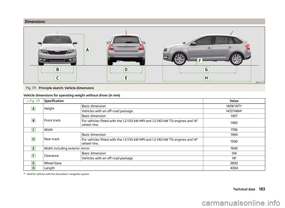
DimensionsFig. 171
Principle sketch: Vehicle dimensions
Vehicle dimensions for operating weight without driver (in mm)
» Fig. 171SpecificationValueAHeightBasic dimension1459/1471 a)Vehicles with an off-road package.1472/1484 a)B
Front track
Basic dimension1457For vehicles fitted with the 1.2 l/55 kW MPI and 1.2 l/63 kW TSI engines and 14"
wheel rims.1463CWidth1706D
Rear track
Basic dimension1494For vehicles fitted with the 1.2 l/55 kW MPI and 1.2 l/63 kW TSI engines and 14"
wheel rims.1500EWidth including exterior mirror1940FClearanceBasic dimension134Vehicles with an off-road package.141GWheel base2602HLength4304a)
Valid for vehicles with the Amundsen+ navigation system.
183Technical data
Page 192 of 204
Index
A
abroad lead-free petrol
139
Abroad Headlights
63
ABS Function
113
Warning light37
Acceptance and recycling of used vehicles131
Accessories128
Adjusting Belt height
15
Exterior mirror68
head restraints70
Interior mirror67
Seat69
Steering wheel10
Adjusting the seats9
Adjustment Beam range
58
Air-conditioning system Air outlet vents
90
Airbag16
Deactivating20
Deactivating the front passenger airbag20
Deployment16
Front airbag17
Head airbag19
Indicator light39
Modifications and damage to the airbag system 130
Side airbag
18
Airbag system16
Air conditioning89
Air distribution control90
Climatronic92
manual air conditioning91
Air distribution control90
Air outlet vents90
Alarm Switching off
53
Triggering53
Alcantara cleaning
137
Anti-lock Braking System113
Anti-theft alarm system Activating/deactivating
54
Trailer126
Anti-theft wheel bolts164
Armrest Front
72
Rear72
artificial leather137
Ashtray76
ASR Warning light
37
Assembling the bar ball, Step 1
122
bar ball, Step 2122
Assist system ABS
113
Assist systems113
ABS37
ASR37
Cruise Control System115
EDL114
ESC37, 113
HBA114
HHC114
Parking aid114
START-STOP116
TCS113
Audio see radio / navigation system
4
Auto Check Control33
Automatic driving lamp control60
Automatic gearbox108
Manual shifting of gears110
Selector lever-emergency unlocking171
Selector lever lock109
Starting-off and driving110
Tiptronic110
Using the selector lever109
Automatic gearbox modes109
Automatic load deactivation151
automatic transmission selector lever lock defect
110
Automatic transmission Kickdown
110
Selector lever lock109
AUX101
B
Ball head Check fitting
123
Ready position121
Battery In the remote control key
170
Belts12
Belt tensioners15
Bonnet Closing
142
Opening142
Boot Cargo element
84
Class N1 vehicles85
Double-sided floor covering85
Hooks82
See Boot lid55
Storage compartments83
Boot cover Parking position
83
Boot lid automatic locking
55
Closing55
Opening55
189Index
Page 197 of 204

Luggage StorageStorage net bag84
M
Main beam
60
Warning light41
Maintenance see vehicle care
133
Manual air conditioning Air distribution control
90
Operating elements91
Manual gear changing refer to gear changing
108
MAXI DOT See MAXI DOT display
46
MAXI DOT display46
Main menu46
Operation42
Settings47
Maximum permissible weights
181
Maximum speed185
MDI101
Mechanical windows57
open and close57
Media see radio / navigation system
4
MFD See multifunction display
43
Mirror Exterior mirror
68
Make-up65
Mobile phone94
Connecting to the hands-free system96
Modifications128
Modifications and technical alterations Airbags
130
Service129
Spoiler130
Multifunction display Functions43
Information45
Memory44
Operation42
Multimedia99
Multimedia holder77
N
N1
85
Nameplate181
Navigation system4
Nets81
Notes for driving with tyre repaired166
Notes on using wheels152
O
Oil Information messages
36
See Engine oil145
Oil pressure Information messages
36
On-board computer See multifunction display
43
Operating weight181
Operation in winter Diesel fuel
140
Vehicle battery150
Original accessories129
Outside temperature45
Overview Engine compartment
143
Indicator lights34
P
Parking
107
Parking aid114
Parking aid114
Function115
Parking light58
Parking space107
Parking vehicle Parking
107
Passive safety Before setting off
8
Driving safety8
Safety equipment8
Passive Safety8
Payload181
Pedals108
Footmats108
Petrol see fuel
139
Plastic parts133
Pockets on the front seat rests80
Polishing vehicle paint work see vehicle care
133
Power outlet 12 V
76
Power steering Warning light
37
Power windows55
Practical equipment 12-Volt power outlet
76
Net pockets on the front seat rests80
Reflective Vest158
Practical features Storage pockets on the front seats
79
Waste container77
Puncture set164
R
Radiator fan
143
Radio4
Raise vehicle163
Rear interior light
64
194Index