tow bar SKODA RAPID SPACEBACK 2015 1.G User Guide
[x] Cancel search | Manufacturer: SKODA, Model Year: 2015, Model line: RAPID SPACEBACK, Model: SKODA RAPID SPACEBACK 2015 1.GPages: 208, PDF Size: 29.2 MB
Page 171 of 208

The jump-start cable must be connected to the engine earthing point C» Fig. 172 only on vehicles with the START-STOP system.
Starting engine›
Start the engine on the vehicle providing the power and allow it to idle.
›
Start the engine of the vehicle with the discharged battery.
›
If the engine does not start, halt the attempt to start the engine after 10 sec-
onds and wait for 30 seconds before repeating the process.
›
Remove the jump start cables in the reverse order as attachment.
Engines in vehicles with the vehicle battery in the boot
The positive terminal
A
is located under a cover in the engine compartment
» Fig. 173 .
›
Unlock the retainer tab on the cover in direction of arrow
1
.
›
Open the cover in the direction of the arrow
2
.
›
Clamp the positive terminal of the jumper cable to the position
A
» Fig. 173 .
›
Clamp the negative terminal of the jumper cable to the earthing point of the
engine
D
» Fig. 172 or to a metal part firmly connected to the engine block or
directly to the engine block.
›
Remove the jump start cables in the reverse order as attachment.
Both batteries must have a rated voltage of 12 V. The capacity (Ah) of the bat-
tery supplying the power must not be significantly less than the capacity of
the discharged battery in your vehicle.
Jump-start cables
Only use jump-start cables which have an adequately large cross-section and
insulated terminal clamps. Observe the instructions of the jumper lead manu-
facturer.
Positive cable – colour coding in the majority of cases is red.
Negative cable – colour coding in the majority of cases is black.
WARNING■
Do not clamp the jump-start cable to the negative terminal of the dis-
charged battery. There is the risk of detonating gas seeping out of the bat-
tery being ignited by the strong spark resulting from the engine being star-
ted.■
The non-insulated parts of the terminal clamps must never touch each
other – there is a risk of short circuit!
WARNING (Continued)■ The jump-start cable connected to the positive terminal of the battery
must not come into contact with electrically conducting parts of the vehicle
– there is a risk of short circuit!■
Route the jump-start cables so that they cannot be caught by any rotat-
ing parts in the engine compartment.
Towing the vehicle
Introduction
Fig. 174
Braided tow rope / Spiral tow rope
This chapter contains information on the following subjects:
Front towing eye
170
Rear towing eye
171
Vehicles with a tow hitch
171
For towing a braided tow rope is to be used » Fig. 174-
.
When towing, the following guidelines must be observed.
Vehicles with manual transmission may be towed in with a tow bar or a tow
rope or with the front or rear wheels raised.
Vehicles with automatic transmission may be towed in with a tow bar or a tow
rope or with the front wheels raised. If the vehicle is raised at the rear, the au-
tomatic gearbox will be damaged! If possible, the vehicle should be towed with
the engine running or at least with the ignition on.
Driver of the tow vehicle
›
Engage the clutch gently when starting off or depress the accelerator partic-
ularly gently if the vehicle is fitted with an automatic gearbox.
169Emergency equipment and self-help
Page 172 of 208

›Only then approach correctly when the rope is taut.
The maximum towing speed is 50 km/h.
Driver of the towed vehicle›
Switch on the ignition so that the steering wheel is not locked and so that
the turn signal lights, windscreen wipers and windscreen washer system can
be used.
›
Take the vehicle out of gear or move the selector lever into position N if the
vehicle is fitted with an automatic gearbox.
Please note that the brake servo unit and power steering only operate if the
engine is running. If the engine is not running, significantly more physical force
is required to depress the brake pedal and steer the vehicle.
If using a tow rope, ensure that it is always kept taught.
General information for the towing process
Both drivers should be familiar with the problems which might possibly occur while a vehicle is being towed. Unskilled drivers should not attempt to tow an-
other vehicle or to be towed in one.
The vehicle must be transported on a special breakdown vehicle or trailer if it
is not possible to tow the vehicle in the way described or if the towing dis-
tance is greater than 50 km.
If the gearbox no longer contains any oil, your vehicle must only be towed with
the front axle raised clear of the ground or on a breakdown vehicle or trailer.
To protect both vehicles when tow-starting or towing, the tow rope should be
elastic. Thus only plastic fibre rope or a rope made out of a similarly elastic ma-
terial should be used.
Attach the tow rope or the tow bar to the towing eyes » page 170 or
» page 171 to the detachable ball head of the towing equipment » page 121 .
WARNING■
When towing, exercise increased caution.■For towing no spiral tow rope is to be used » Fig. 174- , the towing eye
may unscrew out of the vehicle - there is a risk of accidents.■
The tow rope should not be twisted - there is a risk of accidents.
CAUTION■ Do not start engine by towing - there is a risk of damaging the engine parts.
The battery from another vehicle can be used as a jump-start aid » page 168,
Jump-starting .■
There is always a risk of excessive stresses and damage resulting at the
points to which you attach the tow rope or tow bar when you attempt to tow a
vehicle which is not standing on a paved road.
Note
We recommend using a tow rope from ŠKODA Original Accessories, which is
available from a ŠKODA Partner.
Front towing eye
Fig. 175
Removing the cap/installing the towing eye
Read and observe
and on page 170 first.
Removing/installing the cap
›
Press on the cap in the direction of the arrow
1
» Fig. 175 .
›
Remove the cap in the direction of the arrow
2
.
›
After unscrewing the cap of the towing eye, insert the cap in the region of
the arrow
1
and then press the opposite side of the cap.
The cap must engage firmly.
Removing/installing the towing eye
›
Manually screw the towing eye as far as it will go in the direction of the ar-
row
3
» Fig. 175 » .
For tightening purposes, we recommend, for example, using the wheel
wrench, towing eye from another vehicle or a similar object that can be pushed through the eye.
170Do-it-yourself
Page 173 of 208

›Unscrew the towing eye against the direction of the arrow 3.WARNINGThe towing eye must always be screwed in fully and firmly tightened, oth-
erwise the towing eye can tear when towing or tow-starting.
Rear towing eye
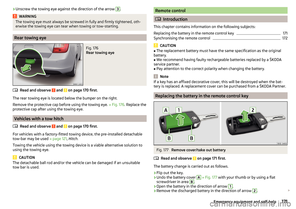
Fig. 176
Rear towing eye
Read and observe and on page 170 first.
The rear towing eye is located below the bumper on the right.
Remove the protective cap before using the towing eye. » Fig. 176. Replace the
protective cap after using the towing eye.
Vehicles with a tow hitch
Read and observe
and on page 170 first.
For vehicles with a factory-fitted towing device, the pre-installed detachable
tow-bar may be used » page 121, Hitch .
Towing the vehicle using the towing device is a viable alternative solution to
using the towing eye.
CAUTION
The detachable ball rod and/or the vehicle can be damaged if an unsuitable
tow bar is used.Remote control
Introduction
This chapter contains information on the following subjects:
Replacing the battery in the remote control key
171
Synchronising the remote control
172
CAUTION
■ The replacement battery must have the same specification as the original
battery.■
We recommend having faulty rechargeable batteries replaced by a ŠKODA
service partner.
■
Pay attention to the correct polarity when changing the battery.
Note
If a key has an affixed decorative cover, this will be destroyed when the bat-
tery is replaced. A replacement cover can be purchased from a ŠKODA Partner.
Replacing the battery in the remote control key
Fig. 177
Remove cover/take out battery
Read and observe
on page 171 first.
The battery change is carried out as follows.
›
Flip out the key.
›
Undo the battery cover
A
» Fig. 177 with your thumb or by using a flat
screwdriver in area
B
.
›
Open the battery in the direction of arrow
1
.
›
Remove the discharged battery in the direction of arrow
2
.
171Emergency equipment and self-help
Page 186 of 208

Maximum permissible front axle load
Maximum permissible rear axle load
Vehicle identification number (VIN)
The vehicle identification number - VIN (vehicle body number) is stamped into
the engine compartment on the right hand suspension strut dome. This num-
ber is also located on a sign on the lower left hand edge below the windscreen
(together with a VIN bar code), and on the type plate.
The VIN number can also be displayed in the Infotainment » Owner´s Manual
Infotainment , chapter CAR - vehicle settings .
Engine number
The engine number (three-digit identifier and serial number) is stamped on the
engine block.
Supplementary Information (applies to Russia)
The full type approval number of the means of transport is indicated in the
registration documents, field 17.
Maximum permissible towed weight
The listed maximum allowable trailer weight is only valid for altitudes up to
1000 m above sea level.
The engine output falls as altitude increases, as does the vehicle's climbing
power. Therefore, for every additional 1,000 m in height (or part), the maximum
permissible towed weight must be reduced by 10%.
The towed weight is made up of the actual weights of the loaded towing vehi-
cle and the loaded trailer.WARNINGDo not exceed the specified maximum permissible weights – risk of acci-
dent and damage!
Operating weight
The value represents the lightest possible vehicle weight without any addi-
tional equipment that would add to the weight, e.g. air conditioning, spare
wheel.
The specified operating weight is for orientation purposes only.
The operating weight also contains the weight of the driver (75 kg), the weight
of the operating fluids, the tool kit, and a fuel tank filled to 90 % capacity.
1011Operating weightEngineGearboxOperating weight (kg)1.2 l/66 kW TSIMG1160DSG11941.2 l/81 kW TSIMG11801.4 l/92 kW TSIDSG1212DSG (Green tec)12211.6 l./81 kW MPIMG1160AG12001.4 l/66 kW TDI CRMG1229DSG12501.6 l/85 kW TDI CRMG1275
Note
If required, you can find out the precise weight of your vehicle at a specialist
garage.
Payload
It is possible to calculate the approximate maximum payload from the differ-
ence between the permissible total weight and the operating weight.
The payload consists of the following weights.
▶ The weight of the passengers.
▶ The weight of all items of luggage and other loads.
▶ The weight of the roof, including the roof rack system.
▶ The weight of the equipment that is excluded from the operating weight.
▶ Trailer draw-bar load when towing a trailer (max. 50 kg).
Measurement of fuel consumption and CO
2 emissions according to
ECE Regulations and EU Directives
The data on fuel consumption and CO 2 emissions were not available at the
time of going to press.
The data on fuel consumption and CO 2 emissions are given on the ŠKODA
websites or in the sales and technical vehicle documentation.
The measurement of the intra-urban cycle begins with a cold start of the en-
gine. Afterwards urban driving is simulated.
184Technical data
Page 192 of 208

Index
A
abroad lead-free petrol
141
Abroad Headlights
63
ABS Operation
110
Warning light33
Acceptance and recycling of used vehicles133
Accessories130
Adjusting Exterior mirror
68
head restraints69
Seat69
Steering wheel9
Adjusting the seats8
Adjustment Beam range
59
Advance warning/emergency braking Warning light
38
Air-conditioning system Air outlet vents
94
Airbag14
Deactivating18
Deactivating the front passenger airbag18
Deployment15
Front airbag15
Head airbag17
Modifications and damage to the airbag system 132
Side airbag
16
Warning light34
Airbag system14
Air conditioning90
Air distribution control93
Climatronic92
Manual air conditioning91
Air distribution control93
Air outlet vents94
Alarm Enable/disable
54
Switch off54
Trailer128
Triggering54
Alcantara cleaning
139
Anodized parts Refer to vehicle maintenance
136
Anti-lock braking system (ABS)110
Anti-theft alarm system Enable/disable
54
Trailer128
Anti-theft wheel bolts163
Armrest Front
71
Rear71
artificial leather139
Ashtray75
Assembling the tow bar, Step 1
123
tow bar, Step 2124
Assist systems109
Auto-check control39
Automatic driving lamp control61
Automatic gearbox104
Selector lever-emergency unlocking172
Selector lever lock105
Starting-off and driving106
Tiptronic105
Using the selector lever104
Automatic gearbox modes104
Automatic load deactivation153
automatic transmission selector lever lock defect
105
Automatic transmission Kick-down
106
Malfunctions36
Selector lever lock105
Warning light36
Warning messages36
AUX80
Avoiding damage to your vehicle108
B
Bags on the backs of the front seats
79
Ball head Check fitting
124
Ready position122, 123
Battery In the remote control key
171
Belts11
Belt tensioners13
Bonnet Closing
144
Opening144
Boot Cargo element
85
Class N1 vehicles86
Hooks83
See Boot lid55
Storage compartments85
Boot cover Parking position
84
Boot lid automatic locking
55
Closing55
Opening55
Brake Assist (HBA)111
Brake booster102
brake fluid specification
150
Brake fluid149
Checking150
Information messages32
190Index
Page 198 of 208

Phonesee Infotainment4
Plastic parts135
Pocket in the luggage compartment
83
Pockets on the inner sides of the front seats
79
Polishing vehicle paint work see vehicle care
135
Power outlet 12 V
75
Power steering/steering lock (KESSY system) Warning light
32
Power windows56
Button in the front passenger door57
Practical equipment 12-Volt power outlet
75
Reflective vest160
Practical features Pockets on the backs of the front seats
79
Pockets on the inner sides of the front seats79
Waste container76
Protective films135
Puncture set165
R
Radiator fan
145
Radio see Infotainment
4
Raise vehicle164
Rear interior light
64
Rear fog light61
Warning light34
Rear mirror67
Exterior mirror68
Rear view mirror Interior mirror
67
Refuelling141
Fuel141
Remote control Locking
50
Replacing the battery171
Synchronisation process172
Unlocking50
Remote control key Replacing the battery
171
Removing the tow bar, Step 1
125
tow bar, Step 2125
Repairs and technical alterations130
Replacement parts130
Replacing Bulb for main beam, daytime running lights andparking light
179
Bulb for the fog light180
Bulb for the licence plate light181
Bulb in rear light182
Fuses174
Fuses in the dash panel175
Fuses in the engine compartment176
High beam bulb (halogen headlights)179
Rear window wiper blade173
Vehicle battery153
windscreen wiper blades173
Replenishing Coolant
149
Engine oil147
Windscreen washer fluid145
Revolution counter29
Roof Load
90
Roof rack89
mounting points89
Roof load90
Rubber seals136
Running-in Brake linings106
Engine106
Tyres106
S
SAFE See Safe securing system
52
SAFELOCK See Safe securing system
52
Safe securing system52
Safety8
Child safety19
Child safety seats19
Correct seated position8
Head restraints69
ISOFIX22
TOP TETHER24
Save electrical energy106
Save fuel106
Seals Vehicle care
136
Seat Adjusting
69
Seat belt height adjustment
12
Warning light32, 36
Seat belts11
Belt tensioners13
fastening and unfastening13
Inertia reels13
The physical principle of a frontal collision12
Seat features70
Seats Front armrest
71
Head restraints69
Heating70
Rear armrest71
Seat backrests72
Seats and head restraint69
196Index