engine SKODA RAPID SPACEBACK 2015 1.G Owner's Guide
[x] Cancel search | Manufacturer: SKODA, Model Year: 2015, Model line: RAPID SPACEBACK, Model: SKODA RAPID SPACEBACK 2015 1.GPages: 208, PDF Size: 29.2 MB
Page 66 of 208
The system is turned off when any of the following is present.
▶ The vehicle is locked.
▶ The ignition is switched on.
▶ About 30 seconds after all the doors have been closed.
Rear interior light
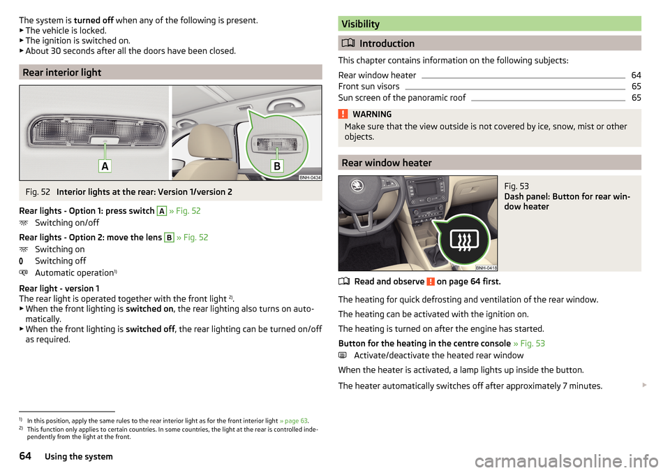
Fig. 52
Interior lights at the rear: Version 1/version 2
Rear lights - Option 1: press switch
A
» Fig. 52
Switching on/off
Rear lights - Option 2: move the lens
B
» Fig. 52
Switching on
Switching off
Automatic operation 1)
Rear light - version 1
The rear light is operated together with the front light 2)
.
▶ When the front lighting is switched on, the rear lighting also turns on auto-
matically.
▶ When the front lighting is switched off, the rear lighting can be turned on/off
as required.
Visibility
Introduction
This chapter contains information on the following subjects:
Rear window heater
64
Front sun visors
65
Sun screen of the panoramic roof
65WARNINGMake sure that the view outside is not covered by ice, snow, mist or other
objects.
Rear window heater
Fig. 53
Dash panel: Button for rear win-
dow heater
Read and observe on page 64 first.
The heating for quick defrosting and ventilation of the rear window.
The heating can be activated with the ignition on.
The heating is turned on after the engine has started.
Button for the heating in the centre console » Fig. 53
Activate/deactivate the heated rear window
When the heater is activated, a lamp lights up inside the button.
The heater automatically switches off after approximately 7 minutes.
1)
In this position, apply the same rules to the rear interior light as for the front interior light
» page 63.
2)
This function only applies to certain countries. In some countries, the light at the rear is controlled inde-
pendently from the light at the front.
64Using the system
Page 67 of 208
If the engine is switched off when the heating is on and turned back on again
within 10 minutes, the heating is continued.
Note
■ If the on-board voltage decreases, the heating switches off automatically
» page 153 , Automatic load deactivation .■
If the light is flashing inside the button the heater is off due to low battery.
Front sun visors
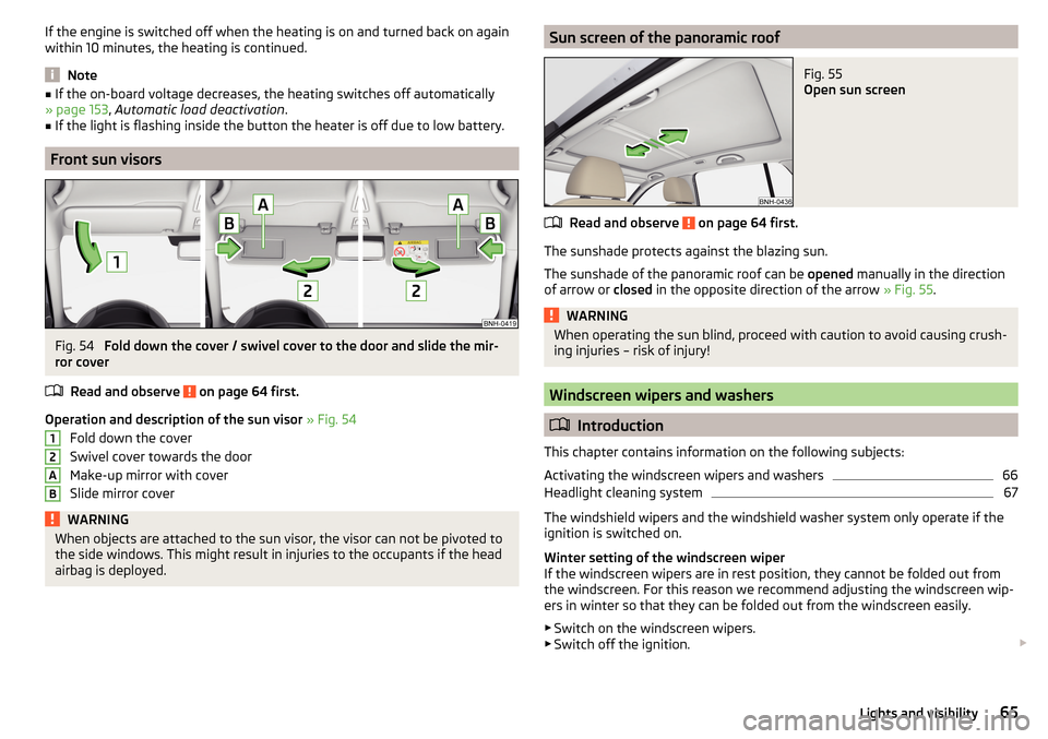
Fig. 54
Fold down the cover / swivel cover to the door and slide the mir-
ror cover
Read and observe
on page 64 first.
Operation and description of the sun visor » Fig. 54
Fold down the cover
Swivel cover towards the door
Make-up mirror with cover
Slide mirror cover
WARNINGWhen objects are attached to the sun visor, the visor can not be pivoted to
the side windows. This might result in injuries to the occupants if the head
airbag is deployed.12ABSun screen of the panoramic roofFig. 55
Open sun screen
Read and observe on page 64 first.
The sunshade protects against the blazing sun.
The sunshade of the panoramic roof can be opened manually in the direction
of arrow or closed in the opposite direction of the arrow » Fig. 55.
WARNINGWhen operating the sun blind, proceed with caution to avoid causing crush-
ing injuries – risk of injury!
Windscreen wipers and washers
Introduction
This chapter contains information on the following subjects:
Activating the windscreen wipers and washers
66
Headlight cleaning system
67
The windshield wipers and the windshield washer system only operate if the
ignition is switched on.
Winter setting of the windscreen wiper
If the windscreen wipers are in rest position, they cannot be folded out from
the windscreen. For this reason we recommend adjusting the windscreen wip-
ers in winter so that they can be folded out from the windscreen easily.
▶ Switch on the windscreen wipers.
▶ Switch off the ignition.
65Lights and visibility
Page 68 of 208
The windscreen wipers remain in the position in which they were when
switching off the ignition.
The service position can also be used as a winter position » page 173.WARNING■
Properly maintained windscreen wiper blades are essential for clear visi-
bility and safe driving » page 173.■
Do not use the windscreen washer system at low temperatures, without
heating the windscreen beforehand. The window washer fluid could other-
wise freeze on the windscreen and restrict the view to the front.
CAUTION
■ In cold temperatures and during the winter, check before switching on the
ignition that the wiper blades are not frozen to the windscreen. If the wind-
screen wipers are switched on when the blades are frozen to the windscreen,
this may damage both the blades and windscreen wiper motor!■
Carefully peel frozen wiper blades off the windscreen.
■
Remove snow and ice from the windscreen wipers before driving.
■
If the windscreen wipers are handled carelessly, there is a risk of damage to
the windscreen.
■
Do not switch on the ignition if the front wiper arms are retracted. The wiper
arms could damage the paint of the bonnet.
Note
Depending on vehicle equipment, the windscreen washer jets can be heated
automatically after starting the engine.
Activating the windscreen wipers and washers
Fig. 56
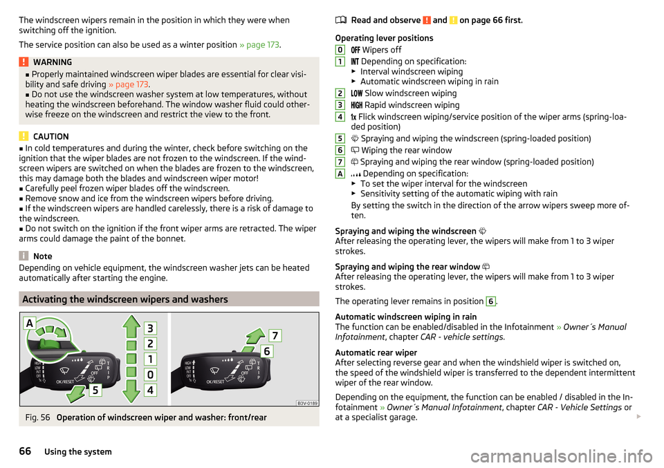
Operation of windscreen wiper and washer: front/rear
Read and observe and on page 66 first.
Operating lever positions
Wipers off
Depending on specification:
▶ Interval windscreen wiping
▶ Automatic windscreen wiping in rain
Slow windscreen wiping
Rapid windscreen wiping
Flick windscreen wiping/service position of the wiper arms (spring-loa-
ded position)
Spraying and wiping the windscreen (spring-loaded position)
Wiping the rear window
Spraying and wiping the rear window (spring-loaded position)
Depending on specification:
▶ To set the wiper interval for the windscreen
▶ Sensitivity setting of the automatic wiping with rain
By setting the switch in the direction of the arrow wipers sweep more of-
ten.
Spraying and wiping the windscreen
After releasing the operating lever, the wipers will make from 1 to 3 wiper
strokes.
Spraying and wiping the rear window
After releasing the operating lever, the wipers will make from 1 to 3 wiper
strokes.
The operating lever remains in position
6
.
Automatic windscreen wiping in rain
The function can be enabled/disabled in the Infotainment » Owner´s Manual
Infotainment , chapter CAR - vehicle settings .
Automatic rear wiper
After selecting reverse gear and when the windshield wiper is switched on,
the speed of the windshield wiper is transferred to the dependent intermittent
wiper of the rear window.
Depending on the equipment, the function can be enabled / disabled in the In- fotainment » Owner´s Manual Infotainment , chapter CAR - Vehicle Settings or
at a specialist garage.
01234567A66Using the system
Page 69 of 208

WARNINGAutomatic wiping during rain is only a support. The driver is not released
from the responsibility to set the function of the windscreen wipers man-
ually depending on the visibility conditions.
Headlight cleaning system
Read and observe
and on page 66 first.
To clean the headlights, the headlamp is also sprayed after every ten squirts.The headlight washer system works under the following conditions. The ignition is switched on.
The low beam is switched on.
The outside temperature is about -11° C to +36° C.
To ensure the correct functioning of the system, even in winter, this needs to
be regularly cleared of snow and ice, e.g. free with a de-icing spray.
CAUTION
Never remove the nozzles from the headlight cleaning system by hand – risk of
damage!
Rear mirror
Introduction
This chapter contains information on the following subjects:
Interior mirror dimming
67
Exterior mirror
68WARNING■ Convex (curved outward) or aspheric exterior mirrors increase the field of
vision. They do, however, make objects appear smaller in the mirror. These
mirrors are therefore only of limited use for estimating distances to the fol-
lowing vehicles.■
Whenever possible use the interior mirror for estimating the distances to
the following vehicles.
Interior mirror dimmingFig. 57
Interior mirror: manual dimming/auto-darkening
Read and observe
on page 67 first.
Mirrors with manual dimming » Fig. 57 -
Basic position of the mirror
Mirror blackout
Mirror with automatic dimming
After starting the engine, the mirror darkens » Fig. 57 -
automatically.
The mirror dimming is controlled by the light incident on the sensors on the
front and back of the mirror.
When the interior lights are switched on or the reverse gear is engaged, the
mirror always moves back into the basic position (not dimmed).
Do not attach external devices (e.g. navigation systems) on to the windscreen
or in the vicinity of the interior mirror »
.
WARNING■
The illuminated display of an external navigation device can lead to op-
erational faults to the automatic dimming interior mirror – risk of accident.■
Automatic mirror dimming operates only properly if the light striking the
sensors is not affected by other objects.
1267Lights and visibility
Page 70 of 208

WARNINGThe mirrors with automatic dimming contain an electrolyte liquid which can
escape if mirror glass is broken.■
The leaking electrolytic fluid can irritate the skin, eyes and breath appara-
tus.
■
If your eyes or skin come into contact with the electrolytic fluid, immedi-
ately wash the affected area for a few minutes long with a lot of water. If
necessary get medical assistance.
Exterior mirror
Fig. 58
Exterior mirror controls: mechanical/electrical
Read and observe
on page 67 first.
Adjust the position
The mirror can be adjusted to the desired position by moving the knob in the
direction of the arrow » Fig. 58.
The movement of the mirror surface is identical to the movement of the rotary
knob.
Electrically-adjustable mirrors
The knob can be moved (depending on vehicle equipment) into the following
positions » Fig. 58 -
.
Adjust the left mirror
Adjust the right mirror
Switch off mirror control
Mirror heater
The mirror heating only works when the engine is running.
Folding in the exterior mirrors
The whole exterior mirror can be manually folded towards the side windows. To put it back into its original position, it should be folded back from the side
window until it audibly clicks into place.WARNINGDo not touch the exterior mirror surfaces, if the exterior mirror heating is
switched on - hazard of burning.
Note
If the electrical mirror setting fails at any time, the mirrors can be adjusted by
hand by pressing on the edge of the mirror surface.68Using the system
Page 72 of 208

Headrests - removing and installingFig. 61
Front head restraints: removal/installation
Fig. 62
Rear head restraints: removal/installation
Read and observe
on page 69 first.
Front restraint
›
Pull the restraint out of the seat backrest as far as the stop.
›
Press locking button
A
in the direction of arrow
1,
and pull out the head re-
straint in the direction of arrow
2
» Fig. 61 .
›
To re-insert the head restraint, push it far enough down into the seat back-
rest in the direction of arrow
3
until the locking button clicks into place.
Rear restraint
›
Pull the restraint out of the seat backrest as far as the stop.
›
Press locking button
B
in the direction of arrow
4
, while at the same time
using a flat-headed screwdriver with a max. width of 5 mm to press the lock-
ing button in opening
C
in the direction of arrow
5
» Fig. 62 .
›
Remove the restraint in the direction of arrow
6
.
›To re-insert the head restraint, push it far enough down into the seat back-
rest in the direction of arrow 7 until the locking button clicks into place.WARNINGPlease note the following points about the head restraint settings » page 8 , Correct and safe seated position .
CAUTION
Store the head restraints that were removed in such a way that they are not
damaged or soiled.
Note
In sports seats, the head restraints are integrated into the seat backrests and
cannot be removed.
Seat features
Introduction
This chapter contains information on the following subjects:
Front seat heating
70
Front armrest setting
71
Rear armrest setting
71
Seat backrests
72
Front seat heating
Fig. 63
Buttons for heating the front
seats
The seat backrests and seats can be heated electrically.
The heat output can be adjusted with the ignition on.
The heater is turned on after the engine has started.
70Using the system
Page 78 of 208

›Connect the plug for the electrical appliance to the socket.WARNINGInstructions for devices connected to the socket.■Safely stow away all devices during the journey to prevent them from be-
ing thrown around the interior in the event of a sudden braking manoeuvre
or an accident – risk of death!■
The devices may warm up during operation – risk of injury or fire! If the
device becomes too hot, switch it off and disconnect it from the power sup-
ply immediately.
WARNINGWhen using the socket the following notes are to be observed.■The socket also operates if the ignition is switched off. When leaving the
vehicle, never leave persons who are not completely independent, such as
children, unattended in the vehicle.■
Improper use of the power sockets and the electrical accessories can
cause fires, burns and other serious injuries.
CAUTION
■ The socket can only be used for the connection of approved electrical acces-
sories with a total power consumption of up to 120 watts, otherwise the elec-
trical system of the vehicle may be damaged.■
Connecting appliances when the engine is not running will drain the battery
of the vehicle!
■
Switch off the devices connected to the power sockets before you switch
the ignition on or off and before starting the engine, to avoid damage from
voltage fluctuations.
Waste containerFig. 75
Waste container: inserting and moving/opening
Fig. 76
Replacing bags
Read and observe
on page 73 first.
The waste container can be inserted into the storage compartment in the
door.
Insert waste container
›
Position the waste container at the front edge of the slot.
›
Push the waste container to the back in the direction of the arrow
1
» Fig. 75 .
›
Move the waste container in the direction of the arrows as required
2
.
Remove the waste container
›
Remove the waste container in the opposite direction to the arrow
1
» Fig. 75 .
76Using the system
Page 92 of 208
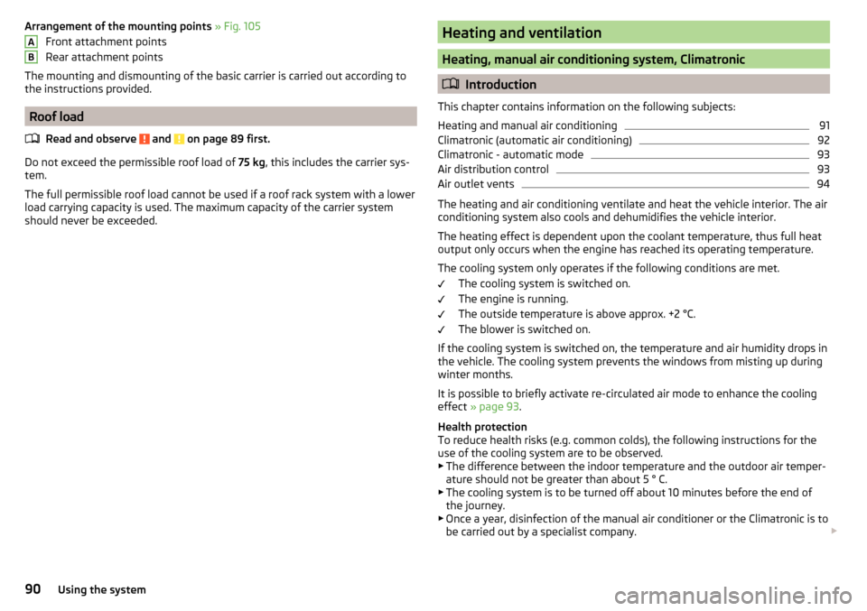
Arrangement of the mounting points » Fig. 105
Front attachment points
Rear attachment points
The mounting and dismounting of the basic carrier is carried out according to the instructions provided.
Roof load
Read and observe
and on page 89 first.
Do not exceed the permissible roof load of 75 kg, this includes the carrier sys-
tem.
The full permissible roof load cannot be used if a roof rack system with a lower
load carrying capacity is used. The maximum capacity of the carrier system
should never be exceeded.
ABHeating and ventilation
Heating, manual air conditioning system, Climatronic
Introduction
This chapter contains information on the following subjects:
Heating and manual air conditioning
91
Climatronic (automatic air conditioning)
92
Climatronic - automatic mode
93
Air distribution control
93
Air outlet vents
94
The heating and air conditioning ventilate and heat the vehicle interior. The air
conditioning system also cools and dehumidifies the vehicle interior.
The heating effect is dependent upon the coolant temperature, thus full heat
output only occurs when the engine has reached its operating temperature.
The cooling system only operates if the following conditions are met. The cooling system is switched on.
The engine is running.
The outside temperature is above approx. +2 °C.
The blower is switched on.
If the cooling system is switched on, the temperature and air humidity drops in the vehicle. The cooling system prevents the windows from misting up during
winter months.
It is possible to briefly activate re-circulated air mode to enhance the cooling
effect » page 93 .
Health protection
To reduce health risks (e.g. common colds), the following instructions for the
use of the cooling system are to be observed. ▶ The difference between the indoor temperature and the outdoor air temper-
ature should not be greater than about 5 ° C.
▶ The cooling system is to be turned off about 10 minutes before the end of
the journey.
▶ Once a year, disinfection of the manual air conditioner or the Climatronic is to
be carried out by a specialist company.
90Using the system
Page 93 of 208
WARNING■For your own safety and that of other road users, ensure that all the win-
dows are free of ice, snow and misting. The blower should always be on to
prevent the windows from misting up.■
Under certain circumstances, air at a temperature of about 5 °C can flow
out of the vents when the cooling system is switched on.
CAUTION
■ The air inlet in front of the windscreen must be free from ice, snow or leaves,
for example, to ensure that the heating and cooling system works properly.■
After switching on the cooling Condensation from the evaporator of the air
conditioning may drip down and form a puddle below the vehicle. This is not a
leak!
■
If the coolant temperature is too high, the cooling system is switched off to
ensure that the engine cools down.
Heating and manual air conditioning
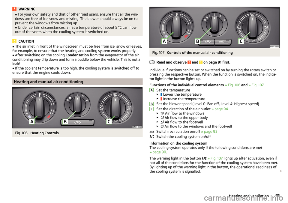
Fig. 106
Heating Controls
Fig. 107
Controls of the manual air conditioning
Read and observe
and on page 91 first.
Individual functions can be set or switched on by turning the rotary switch or
pressing the respective button. When the function is switched on, the indica-
tor light in the button lights up.
Functions of the individual control elements » Fig. 106 and » Fig. 107
Set the temperature
▶ Lower the temperature
▶ Increase the temperature
Set the blower speed (Level 0: Fan off, Level 4: Highest speed)
Set the direction of the air outlet » page 94
▶ Air flow to the windows
▶ Air flow to the upper body
▶ Air flow to the footwell
▶ Air flow to the windows and the footwell
Switch recirculation on/off » page 93
Switch the cooling system on/off
Information on the cooling system
The cooling system operates only if the following conditions are met
» page 90 .
The warning light in the button
» Fig. 107 lights up after activation, even if
not all of the conditions for the function of the cooling system have been met.
By lighting up of the warning light in the button, the operational readiness of
the cooling system is signalled.
ABC91Heating and ventilation
Page 94 of 208
NoteDuring operation of the manual air conditioning, an increase in engine idle
speed may occur under certain circumstances in order to ensure sufficient
heating comfort.
Climatronic (automatic air conditioning)
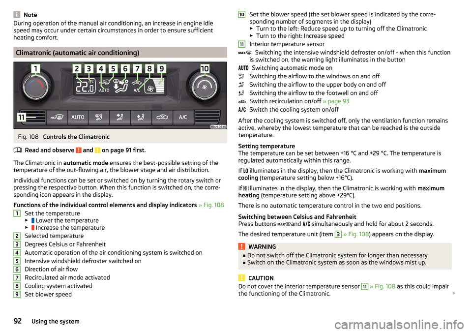
Fig. 108
Controls the Climatronic
Read and observe
and on page 91 first.
The Climatronic in automatic mode ensures the best-possible setting of the
temperature of the out-flowing air, the blower stage and air distribution.
Individual functions can be set or switched on by turning the rotary switch or
pressing the respective button. When this function is switched on, the corre-
sponding icon appears in the display.
Functions of the individual control elements and display indicators » Fig. 108
Set the temperature
▶ Lower the temperature
▶ Increase the temperature
Selected temperature
Degrees Celsius or Fahrenheit
Automatic operation of the air conditioning system is switched on
Intensive windshield defroster switched on
Direction of air flow
Recirculated air mode activated
Cooling system activated
Set blower speed
123456789Set the blower speed (the set blower speed is indicated by the corre-
sponding number of segments in the display)
▶ Turn to the left: Reduce speed up to turning off the Climatronic
▶ Turn to the right: Increase speed
Interior temperature sensor Switching the intensive windshield defroster on/off - when this function
is switched on, the warning light illuminates in the button
Switching automatic mode on
Switching the airflow to the windows on and off
Switching the airflow to the upper body on and off
Switching the airflow to the footwell on and off
Switch recirculation on/off » page 93
Switch the cooling system on/off
After the cooling system is switched off, only the ventilation function remains active, whereby the lowest temperature that can be reached is the outside
temperature.
Setting temperature
The temperature can be set between +16 °C and +29 °C. The temperature is
regulated automatically within this range.
If illuminates in the display, then the Climatronic is working with
maximum
cooling (temperature setting below +16°C).
If illuminates in the display, then the Climatronic is working with
maximum
heating (temperature setting above +29°C).
There is no automatic temperature control in the two end positions.
Switching between Celsius and Fahrenheit
Press buttons and
simultaneously and hold for about 2 seconds.
The desired temperature unit (item 3
» Fig. 108 ) appears on the display.
WARNING■
Do not switch off the Climatronic system for longer than necessary.■Switch on the Climatronic system as soon as the windows mist up.
CAUTION
Do not cover the interior temperature sensor 11 » Fig. 108 as this could impair
the functioning of the Climatronic. 101192Using the system