Socket SKODA RAPID SPACEBACK 2015 1.G Owner's Manual
[x] Cancel search | Manufacturer: SKODA, Model Year: 2015, Model line: RAPID SPACEBACK, Model: SKODA RAPID SPACEBACK 2015 1.GPages: 208, PDF Size: 29.2 MB
Page 64 of 208
Switching off takes place in reverse order.
If the vehicle is not fitted with front fog lights, the rear fog light is switched on
by pulling out the light switch to the only possible setting.
Note
While driving with an accessory connected to the trailer socket (e.g. trailer,
bike carrier) only the equipment is illuminated by the fog light. The towing de-
vice must be installed at the factory or from the ŠKODA original accessories.
Fog lights with the CORNER function
Read and observe
on page 59 first.
The function CORNER provides better illumination of the nearby environmentwhen turning, manoeuvring or anything similar.
The function automatically switches on the fog lights on each side of the ve- hicle, if the following conditions are met.
The turn signal is switched on or the front wheels are turned sharply 1)
.
The vehicle speed is below 40 km/h.
The low beam is switched on.
The fog lights are not switched on.
Note
The two fog lights are switched on when you shift into the reverse gear.
COMING HOME / LEAVING HOME
Read and observe
on page 59 first.
The function COMING HOME ensures that the vehicle's environment is illumi-
nated after switching off the ignition and opening the driver's door.
The function LEAVING HOME ensures that the vehicle's environment is illumi-
nated after unlocking the vehicle with the radio remote control unit.
The function switches the light on only if there is poorer visibility and the light
switch is in the position
.
Enabling / disabling and setting functions
The functions and setting of the lighting duration can be activated or deactiva-
ted in the Infotainment system » Owner´s Manual Infotainment , chap-
ter CARVehicle settings .
CAUTION
■
Poorer visibility is detected by a sensor mounted below the windscreen in
the holder of the inside mirror or in the control panel. Do not attach any stick-
ers or similar objects in front of the sensor in order to avoid impairing the func-
tion or its reliability.■
If this option is always enabled, then the battery is heavily loaded.
Hazard warning light system
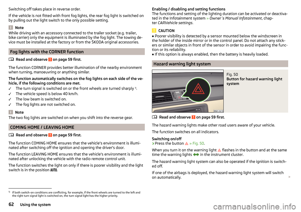
Fig. 50
Button for hazard warning light
system
Read and observe on page 59 first.
The hazard warning lights make other road users aware of your vehicle.
The function switches on all indicators.
Switching on/off
›
Press the button
» Fig. 50 .
When you turn it on the warning light
flashes in the button and at the same
time the warning lights
in the instrument cluster.
The hazard warning light system can also be operated if the ignition is switch-
ed off.
If one of the airbags is deployed, the hazard warning light system will switch
on automatically.
1)
If both switch-on conditions are conflicting, for example, if the front wheels are turned to the left and
the right turn signal light is switched on, the turn signal light has the higher priority.
62Using the system
Page 77 of 208

Cigarette lighterFig. 72
Cigarette lighter
Read and observe on page 73 first.
Use
›
Press the igniter in as far as the stop » Fig. 72.
›
Wait until the igniter pops out.
›
Remove the glowing igniter and use immediately.
›
Place the cigarette lighter back into the socket.
WARNING■
The cigarette lighter also works if the ignition is switched off. When leav-
ing the vehicle, never leave persons who are not completely independent,
such as children, unattended in the vehicle. These could operate the lighter
and get burned, start a fire or damage the interior.■
Take care when using the cigarette lighter! Improper usage can cause
burns.
Note
The cigarette lighter socket can also be used as a 12 volt socket.AshtrayFig. 73
Remove front / rear ashtray
Read and observe
on page 73 first.
The ashtray can be used for discarding ash, cigarettes, cigars and the like » .
Removing/inserting
›
When removing, do not hold the ashtray on the cover.
›
Pull out the ashtray in the direction of the arrow » Fig. 73.
Insertion takes place in reverse order.
WARNINGNever place hot or flammable objects in the ashtray – risk of fire!
12-Volt power outlet
Fig. 74
Cover of the 12 volt power outlet
Read and observe on page 73 first.
Use
›
Remove the socket cover » Fig. 74.
75Transporting and practical equipment
Page 78 of 208

›Connect the plug for the electrical appliance to the socket.WARNINGInstructions for devices connected to the socket.■Safely stow away all devices during the journey to prevent them from be-
ing thrown around the interior in the event of a sudden braking manoeuvre
or an accident – risk of death!■
The devices may warm up during operation – risk of injury or fire! If the
device becomes too hot, switch it off and disconnect it from the power sup-
ply immediately.
WARNINGWhen using the socket the following notes are to be observed.■The socket also operates if the ignition is switched off. When leaving the
vehicle, never leave persons who are not completely independent, such as
children, unattended in the vehicle.■
Improper use of the power sockets and the electrical accessories can
cause fires, burns and other serious injuries.
CAUTION
■ The socket can only be used for the connection of approved electrical acces-
sories with a total power consumption of up to 120 watts, otherwise the elec-
trical system of the vehicle may be damaged.■
Connecting appliances when the engine is not running will drain the battery
of the vehicle!
■
Switch off the devices connected to the power sockets before you switch
the ignition on or off and before starting the engine, to avoid damage from
voltage fluctuations.
Waste containerFig. 75
Waste container: inserting and moving/opening
Fig. 76
Replacing bags
Read and observe
on page 73 first.
The waste container can be inserted into the storage compartment in the
door.
Insert waste container
›
Position the waste container at the front edge of the slot.
›
Push the waste container to the back in the direction of the arrow
1
» Fig. 75 .
›
Move the waste container in the direction of the arrows as required
2
.
Remove the waste container
›
Remove the waste container in the opposite direction to the arrow
1
» Fig. 75 .
76Using the system
Page 113 of 208
Electronic Differential Lock (EDL)Read and observe
on page 110 first.
EDL prevents the turning of the respective wheel of the driven axle. EDL
brakes the spinning wheel, if necessary, and transmits the driving force to the
other driving wheel. Driving becomes easier on road surfaces with different
traction under each wheel of the driven axle.
The EDL switches off automatically in order to avoid excessive heat generation
on the brake of the wheel being braked. Once the brakes have cooled down,
there is an automatic re-activation of EDL.
Brake Assist (HBA)
Read and observe
on page 110 first.
The HBA increases the braking effect and helps to reduce the braking dis-
tance.
The HBA is activated by the very quick operation of the brake pedal. In order to
achieve the shortest possible braking distance, the brake pedal must be ap-
plied firmly until the vehicle has come to a standstill.
The HBA function is automatically deactivated when the brake pedal is re-
leased.
Hill Start Assist (HHC)
Read and observe
on page 110 first.
When driving on slopes, HHC allows you to move your foot from the brake ped-al to the accelerator pedal without having to use the handbrake.
The system holds the brake pressure produced by the activation of the brake pedal for approx. 2 seconds after the brake pedal is released.
The HHC is active from a 5% slope if the driver's door is closed. HHC is only ev-
er active on slopes when in forward or reverse start off.
Multi collision brake (MCB)
Read and observe
on page 110 first.
The MCB helps to decrease speed after a collision through automatic brakinginterventions and to stabilize the vehicle. This reduces the risk of a subse-
quent crash due to uncontrolled vehicle movement.
The automatic brake interventions can take place only if the following condi-
tions are met.
There was a front, side and rear-end collision of a certain severity.
The impact speed was higher than approx. 10 km/h.
The brakes, the ESL and other required electrical systems remain function-
al after impact.
The accelerator pedal is not actuated.
Trailer stabilization system (TSA)
Read and observe
on page 110 first.
The TSA helps the combination stable in situations where the trailer sways
and then the whole trailer combination.
TSA brakes the individual wheels of the towing vehicle in order to damp the rocking motion of the entire vehicle combination.
The following conditions are required for the correct TSA function. The trailer was shipped from the factory or purchased from the ŠKODA
genuine accessories.
The trailer is electrically connected to the towing vehicle by means of the
trailer socket.
The TCS is activated.
The speed is higher than approx. 60 km/h.
Further information » page 121, Hitch and trailer .
111Assist systems
Page 115 of 208

Approximate range of sensors (in cm)Area » Fig. 124Version 1
(3 sensors)Version 2
(7 sensors)A-120B-60C160160D6060
Audible signals
The interval between the acoustic signals becomes shorter as the clearance is
reduced. A continuous tone sounds from a distance of approx. 30 cm - danger
area. From this moment on do not continue driving!
The acoustic signals can be set in the Infotainment » Owner´s Manual Infotain-
ment , chapter CAR - Vehicle Settings .
Towing a trailer
When towing, or when another accessory is connected to the trailer socket on-
ly the areas
A
and
B
» Fig. 124 are active in the system.
Note
The signal tones for front obstacle recognition are factory-set to be higher
than for rear obstacle recognition.
Display in the Infotainment display
Fig. 125
Display
Read and observe and on page 112 first.
Function keys and obstacle warning » Fig. 125 Depending on the Infotainment type: Switching off park assistant dis-
play. Switching audible parking signals on/off.Message: Look! Safe to move?Colour of an object detected in the collision area (the distance to the
obstacle is less than 30 cm).
Stop driving in the direction of the ob-
stacle!Colour of an object detected in the manoeuvring area (the distance to
the obstacle is more than 30 cm).Colour of an object detected in the outside the manoeuvring area (the
distance to the obstacle is more than 30 cm).System failure (there is no indication of obstacles).
Activation / deactivation
Fig. 126
System key (option 2)
Read and observe and on page 112 first.
Activation
The activation of the system is initiated when the reverse gear is engaged, or
vehicles with the Variant 2, also by pressing the symbol key
» Fig. 126
.
This is confirmed by a short acoustic signal (the symbol in the button lights
up).
Deactivation
On vehicles with Version 1, the system can be deactivated by moving out of re-
verse gear.
For vehicles with Version 2, the system is deactivated by pressing the symbol
button or automatically at a speed over 10 km/h (the symbol
in the but-
ton goes out).
113Assist systems
Page 129 of 208
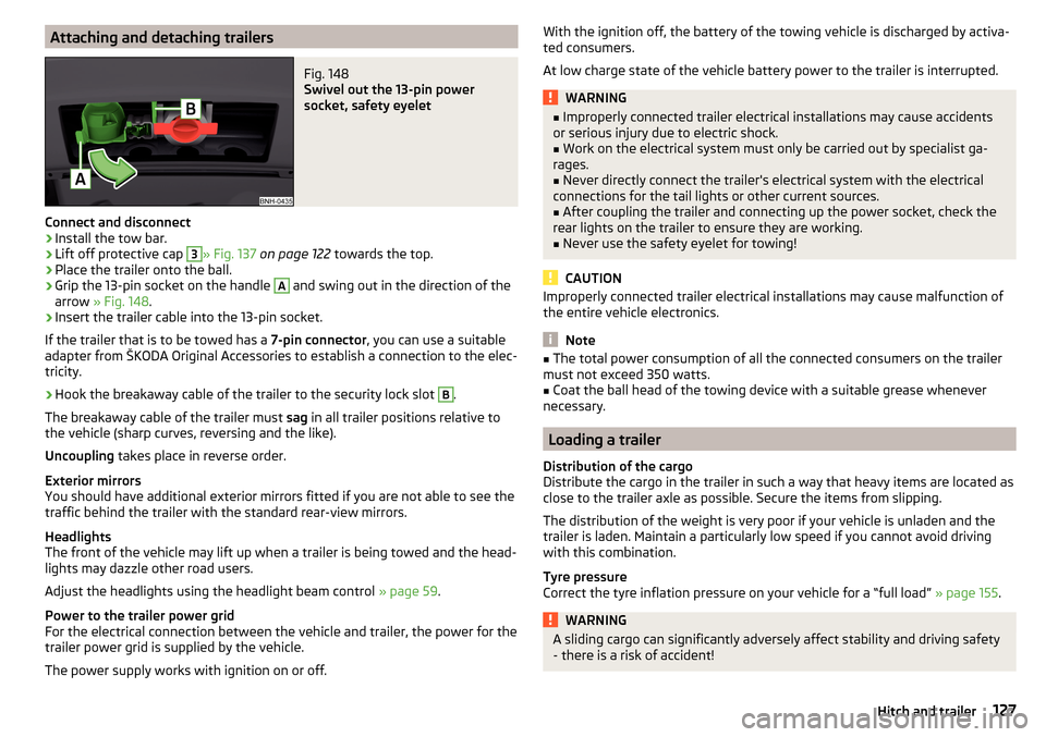
Attaching and detaching trailersFig. 148
Swivel out the 13-pin power
socket, safety eyelet
Connect and disconnect
›
Install the tow bar.
›
Lift off protective cap
3
» Fig. 137 on page 122 towards the top.
›
Place the trailer onto the ball.
›
Grip the 13-pin socket on the handle
A
and swing out in the direction of the
arrow » Fig. 148 .
›
Insert the trailer cable into the 13-pin socket.
If the trailer that is to be towed has a 7-pin connector, you can use a suitable
adapter from ŠKODA Original Accessories to establish a connection to the elec-
tricity.
›
Hook the breakaway cable of the trailer to the security lock slot
B
.
The breakaway cable of the trailer must sag in all trailer positions relative to
the vehicle (sharp curves, reversing and the like).
Uncoupling takes place in reverse order.
Exterior mirrors
You should have additional exterior mirrors fitted if you are not able to see the
traffic behind the trailer with the standard rear-view mirrors.
Headlights
The front of the vehicle may lift up when a trailer is being towed and the head-
lights may dazzle other road users.
Adjust the headlights using the headlight beam control » page 59.
Power to the trailer power grid
For the electrical connection between the vehicle and trailer, the power for the
trailer power grid is supplied by the vehicle.
The power supply works with ignition on or off.
With the ignition off, the battery of the towing vehicle is discharged by activa- ted consumers.
At low charge state of the vehicle battery power to the trailer is interrupted.WARNING■ Improperly connected trailer electrical installations may cause accidents
or serious injury due to electric shock.■
Work on the electrical system must only be carried out by specialist ga-
rages.
■
Never directly connect the trailer's electrical system with the electrical
connections for the tail lights or other current sources.
■
After coupling the trailer and connecting up the power socket, check the
rear lights on the trailer to ensure they are working.
■
Never use the safety eyelet for towing!
CAUTION
Improperly connected trailer electrical installations may cause malfunction of
the entire vehicle electronics.
Note
■ The total power consumption of all the connected consumers on the trailer
must not exceed 350 watts.■
Coat the ball head of the towing device with a suitable grease whenever
necessary.
Loading a trailer
Distribution of the cargo
Distribute the cargo in the trailer in such a way that heavy items are located as
close to the trailer axle as possible. Secure the items from slipping.
The distribution of the weight is very poor if your vehicle is unladen and the
trailer is laden. Maintain a particularly low speed if you cannot avoid driving
with this combination.
Tyre pressure
Correct the tyre inflation pressure on your vehicle for a “full load” » page 155.
WARNINGA sliding cargo can significantly adversely affect stability and driving safety
- there is a risk of accident!127Hitch and trailer
Page 130 of 208

Trailer loadThe permissible trailer load must not be exceeded under any circumstances.Permissible trailer loadEngineGearboxPermissible trailer load, braked (kg)Permissible trailer load, unbraked (kg)Gradients of up to 12 %Gradients of up to 8 %1.2 l/66 kW TSIMG9001000580DSG90010005901.2 l/81 kW TSIMG110012005901.4 l/92 kW TSIDSG12001200600DSG (Green tec)120012006101.6 l./81 kW MPIMG10001100580AG100011006001.4 l/66 kW TDI CRMG10001100610DSG100011006201.6 l/85 kW TDI CRMG12001200630WARNINGThe maximum permissible axle and draw-bar load and the permissible
weight of the trailer must not exceed - this could cause an accident!
Towing a trailer
Driving speed
For safety reasons, do not drive faster than 80 km/h when towing a trailer.
Immediately reduce your speed as soon as even the slightest swaying of the
trailer is detected. Never attempt to stop the trailer from “swaying” by acceler-
ating.
Brakes
Apply the brakes in good time! If the trailer is fitted with a trailer brake, apply
the brakes gently at first, then brake firmly. This will avoid brake jolts resulting
from the trailer wheels locking.
On downhill sections shift down a gear in good time to also use the engine as
a brake.
WARNINGAlways drive particularly carefully with the trailer.
CAUTION
If you tow a trailer frequently, you should also have your vehicle inspected be-
tween service intervals.
Anti-theft alarm system
When the vehicle is locked, the alarm is activated when the electrical connec-
tion to the trailer is interrupted.
Always switch off the anti-theft alarm system before a trailer is coupled or un-
coupled » page 54 .
Conditions for including a trailer in the anti-theft alarm system. The vehicle is factory-fitted with an anti-theft alarm system and towing
device.
The trailer is electrically connected to the towing vehicle by means of the
trailer socket.
128Driving
Page 154 of 208
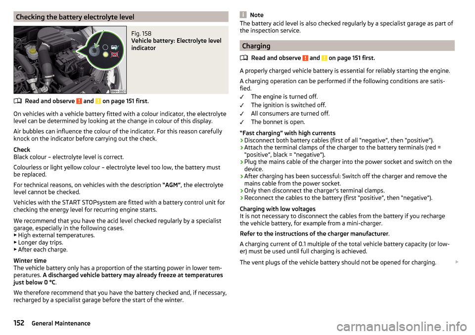
Checking the battery electrolyte levelFig. 158
Vehicle battery: Electrolyte level
indicator
Read and observe and on page 151 first.
On vehicles with a vehicle battery fitted with a colour indicator, the electrolyte
level can be determined by looking at the change in colour of this display.
Air bubbles can influence the colour of the indicator. For this reason carefully
knock on the indicator before carrying out the check.
Check
Black colour – electrolyte level is correct.
Colourless or light yellow colour – electrolyte level too low, the battery must
be replaced.
For technical reasons, on vehicles with the description “AGM”, the electrolyte
level cannot be checked.
Vehicles with the START STOPsystem are fitted with a battery control unit for
checking the energy level for recurring engine starts.
We recommend that you have the acid level checked regularly by a specialist
garage, especially in the following cases. ▶ High external temperatures.
▶ Longer day trips.
▶ After each charge.
Winter time
The vehicle battery only has a proportion of the starting power in lower tem-
peratures. A discharged vehicle battery may already freeze at temperatures
just below 0 °C .
We therefore recommend that you have the battery checked and, if necessary,
recharged by a specialist garage before the start of the winter.
NoteThe battery acid level is also checked regularly by a specialist garage as part of
the inspection service.
Charging
Read and observe
and on page 151 first.
A properly charged vehicle battery is essential for reliably starting the engine.
A charging operation can be performed if the following conditions are satis-
fied.
The engine is turned off.
The ignition is switched off.
All consumers are turned off.
The bonnet is open.
“Fast charging” with high currents
›
Disconnect both battery cables (first of all “negative”, then “positive”).
›
Attach the terminal clamps of the charger to the battery terminals (red =
“positive”, black = “negative”).
›
Plug the mains cable of the charger into the power socket and switch on the
device.
›
After charging has been successful: Switch off the charger and remove the
mains cable from the power socket.
›
Only then disconnect the charger's terminal clamps.
›
Reconnect the cables to the battery (first “positive”, then “negative”).
Charging with low voltages
It is not necessary to disconnect the cables from the battery if you recharge
the vehicle battery, for example from a mini-charger.
Refer to the instructions of the charger manufacturer .
A charging current of 0.1 multiple of the total vehicle battery capacity (or low-
er) must be used until full charging is achieved.
The vent plugs of the vehicle battery should not be opened for charging.
152General Maintenance
Page 155 of 208
WARNING■When you charge a battery, hydrogen is released, and a highly explosive
gas mixture is also produced. An explosion can be caused through sparkling
over during unclamping or loosening of the cable plug while the ignition is
on.■
Creating a bridge between the poles on the battery (e.g. with metal ob-
jects - cables) creates a short circuit - risk of damage to the battery, explo-
sion and burning of the battery, jets of acid spurting out.
■
Avoid creating sparks when working with cables and electrical devices.
Strong sparking represents a risk of injury.
■
Before carrying out any work on the electrical system, switch off the en-
gine, the ignition and all electrical consumers and disconnect the negative
terminal
.
■
“Quick-charging” the vehicle battery is dangerous and requires a special
charger and specialist knowledge.
■
We therefore recommend that vehicle batteries be “rapidly charged” by a
specialist garage.
CAUTION
On vehicles with the START/STOP system, the pole terminal of the charger
must not be connected directly to the negative terminal of the vehicle battery,
but only to the engine earth » page 168, Jump-starting using the battery from
another vehicle .
Replacing
Read and observe
and on page 151 first.
The new vehicle battery must have the same capacity, voltage, current and
size as the original battery. Suitable vehicle battery types can be purchased
from a specialist garage.
We recommend you have the battery replaced by a specialist garage.
Disconnecting and reconnecting
Read and observe
and on page 151 first.
Disconnecting
›
Switch off the ignition.
›
First, disconnect the negative terminal
first, then the positive
terminal
of the battery.
Connecting›First, connect the positive first, then the negative battery terminal.
After disconnecting and re-connecting the vehicle battery, the following func-
tions or devices are partially or completely inoperative.Function / deviceCommissioningTime settings» page 31
CAUTION
■ Disconnect the vehicle battery only with the ignition turned off - there is a
risk of damaging the electrical system of the vehicle.■
Under no circumstances must the battery cables be connected incorrectly –
risk of a cable fire.
Note
■ After disconnecting and re-connecting the vehicle battery, we recommend
having the vehicle checked by a specialist to ensure that the full functionality
of all electrical systems is guaranteed.■
The data of the multi-function display will be reset.
Automatic load deactivation
Read and observe
and on page 151 first.
The vehicle's electrical system automatically prevents the battery from dis-
charging when the battery is being heavily used. This manifests itself by the
following. ▶ The idling speed is raised to allow the generator to deliver more electricity to
the electrical system.
▶ Where necessary, large convenience consumers such as seat heaters and
rear window heaters have their power limited or are shut off completely in
the event of an emergency.
CAUTION
■ Despite such intervention by the vehicle electric system management, the
vehicle battery may be drained. For example, when the ignition is switched on
a long time with the engine turned off or the side or parking lights are turned
on during longer parking.■
Consumers that are supplied via a 12-V power socket can cause the vehicle
battery to discharge when the ignition is switched off.
153Inspecting and replenishing
Page 169 of 208

Preparations for using the breakdown kitRead and observe
on page 166 first.
The following preparatory work must be carried out before using the puncture
repair kit.
›
Switch off the engine.
›
For vehicles with manual transmission select gear 1.
›
On vehicles with automatic transmission , place the selector lever in the P
position.
›
Firmly apply the handbrake.
›
Check that you can carry out the repairs with the breakdown kit » page 166,
General information .
›
Uncouple trailer, if attached.
›
Remove the breakdown kit from the boot.
›
Stick the sticker
1
» Fig. 171 on page 166 on the dashboard in the driver's
field of view.
›
Unscrew the valve cap.
›
Use the valve remover
2
to unscrew the valve core and place it on a clean
surface (rag, paper, etc.).
Sealing and inflating the tyre
Read and observe
on page 166 first.
Sealing
›
Forcefully shake the tyre inflater bottle
10
» Fig. 171 on page 166 back and
forth several times.
›
Firmly screw the inflation hose
3
onto the tyre inflater bottle
10
. The film on
the cap is pierced automatically.
›
Remove the plug from the inflation hose
3
and plug the open end fully onto
the tyre valve.
›
Hold the bottle
10
with the bottom facing upwards and fill all of the sealing
agent from the tyre inflater bottle into the tyre.
›
Remove the filler plug from the tyre valve.
›
Screw the valve core back into the tyre valve using the valve remover
2
.
Inflating
›
Screw the tyre inflation hose
7
» Fig. 171 on page 166 of the air compressor
firmly onto the tyre valve.
›
For vehicles with manual transmission the lever into the neutral position.
›On vehicles with
automatic transmission , place the selector lever in the P
position.›
Start the engine and run it in idle.
›
Plug the connector
6
into the 12-volt socket » page 75.
›
Switch on the air compressor with the ON and OFF switch
9
.
›
Allow the air compressor to run until a pressure of 2.0 - 2.5 bar is achieved.
Maximum run time of 8 minutes » .
›
Switch off the air compressor.
›
If you cannot reach an air pressure of 2.0 - 2.5 bar, unscrew the tyre inflation
hose
7
from the tyre valve.
›
Drive the vehicle 10 metres forwards or backwards to allow the sealing agent
to “distribute” in the tyre.
›
Firmly screw the tyre inflation hose
7
back onto the tyre valve and repeat
the inflation process.
›
Switch off the air compressor.
›
Remove the tyre inflation hose
7
from the tyre valve.
Once a tyre inflation pressure of 2.0 - 2.5 bar is achieved, you can continue the journey.
WARNING■ If the tyre cannot be inflated to at least. 2.0 bar, the damage is too great.
The sealing agent cannot be used to seal the tyre. Do not continue to
drive! Seek help from a specialist garage.■
The tyre inflation hose and air compressor may get hot as the tyre is be-
ing inflated – there is a risk of burning.
CAUTION
Switch off the air compressor after running 8 minutes at the latest – there is a
risk of overheating! Allow the air compressor to cool a few minutes before
switching it on again.
Notes for driving with tyre repaired
Read and observe
on page 166 first.
The inflation pressure of the repaired tyre must be checked after driving for 10
minutes.
If the tyre pressure is 1.3 bar or less
›
Do not continue to drive! The tyre cannot be properly sealed with the
breakdown kit.
167Emergency equipment and self-help