buttons SKODA RAPID SPACEBACK 2015 1.G Owner's Manual
[x] Cancel search | Manufacturer: SKODA, Model Year: 2015, Model line: RAPID SPACEBACK, Model: SKODA RAPID SPACEBACK 2015 1.GPages: 208, PDF Size: 29.2 MB
Page 29 of 208
Using the system
Cockpit
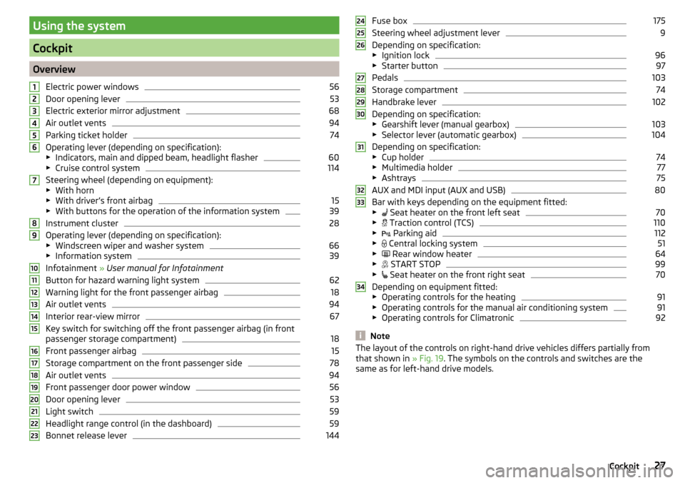
OverviewElectric power windows
56
Door opening lever
53
Electric exterior mirror adjustment
68
Air outlet vents
94
Parking ticket holder
74
Operating lever (depending on specification):
▶ Indicators, main and dipped beam, headlight flasher
60
▶Cruise control system
114
Steering wheel (depending on equipment):
▶ With horn
▶ With driver’s front airbag
15
▶With buttons for the operation of the information system
39
Instrument cluster
28
Operating lever (depending on specification):
▶ Windscreen wiper and washer system
66
▶Information system
39
Infotainment » User manual for Infotainment
Button for hazard warning light system
62
Warning light for the front passenger airbag
18
Air outlet vents
94
Interior rear-view mirror
67
Key switch for switching off the front passenger airbag (in front
passenger storage compartment)
18
Front passenger airbag
15
Storage compartment on the front passenger side
78
Air outlet vents
94
Front passenger door power window
56
Door opening lever
53
Light switch
59
Headlight range control (in the dashboard)
59
Bonnet release lever
1441234567891011121314151617181920212223Fuse box175
Steering wheel adjustment lever
9
Depending on specification:
▶ Ignition lock
96
▶Starter button
97
Pedals
103
Storage compartment
74
Handbrake lever
102
Depending on specification:
▶ Gearshift lever (manual gearbox)
103
▶Selector lever (automatic gearbox)
104
Depending on specification:
▶ Cup holder
74
▶Multimedia holder
77
▶Ashtrays
75
AUX and MDI input (AUX and USB)
80
Bar with keys depending on the equipment fitted:
▶ Seat heater on the front left seat
70
▶
Traction control (TCS)
110
▶
Parking aid
112
▶
Central locking system
51
▶
Rear window heater
64
▶
START STOP
99
▶
Seat heater on the front right seat
70
Depending on equipment fitted:
▶ Operating controls for the heating
91
▶Operating controls for the manual air conditioning system
91
▶Operating controls for Climatronic
92
Note
The layout of the controls on right-hand drive vehicles differs partially from
that shown in » Fig. 19. The symbols on the controls and switches are the
same as for left-hand drive models.242526272829303132333427Cockpit
Page 42 of 208
For vehicles with automatic transmission the recommended gear will be
shown provided the mode for manual switching (Tiptronic) is selected.WARNINGThe driver is always responsible for selecting the correct gear in different
driving situations, such as overtaking.
Driving data (Multifunction display)
Introduction
This chapter contains information on the following subjects:
Operation
40
Information overview
40
Warning when exceeding the set speed
41
Memory
42
The driving data display is only possible with the ignition switched on.
After the ignition is switched on, the function that was last selected before
switching off the ignition is displayed.
For vehicles with a MAXI DOT display, the menu item
Driving data
must be selec-
ted and confirmed in the main menu » page 42, MAXI DOT display .
The setting of the units and the switching on / off the display of some infor-
mation is available possible in the Infotainment » Owner´s Manual Infotain-
ment , chapter CAR - Vehicle Settings .
WARNINGConcentrate fully at all times on your driving! As the driver you are fully re-
sponsible for the operation of your vehicle.OperationFig. 28
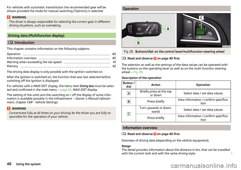
Buttons/dial: on the control lever/multifunction steering wheel
Read and observe
on page 40 first.
The selection as well as the settings of the data values can be operated with the buttons on the operating lever as well as on the multi-function steering
wheel » Fig. 28 .
Description of the operation
Button / dialActionOperationABriefly press at the top or downSelect data / set data valuesBPress brieflyView information / confirm specifica- tionCTurn upwards or down-wardsSelect data / set data valuesPress brieflyView information / confirm specifica- tion
Information overview
Read and observe
on page 40 first.
Overview of driving data (depending on the vehicle equipment).
Range
The detail provides information about the distance in km, that can be travelled
with the current tank and with the same driving style.
40Using the system
Page 45 of 208
›Press and hold the dial G on the multifunction steering wheel
» Fig. 31 on
page 43 .
Main menu items (depending on vehicle equipment) ■Driving data
» page 40
■
Assist systems
» page 45
■
Navigation
» page 44
■
Audio
» page 44
■
Telephone
» page 45 ;
■
Vehicle
» page 39 , Auto-check control
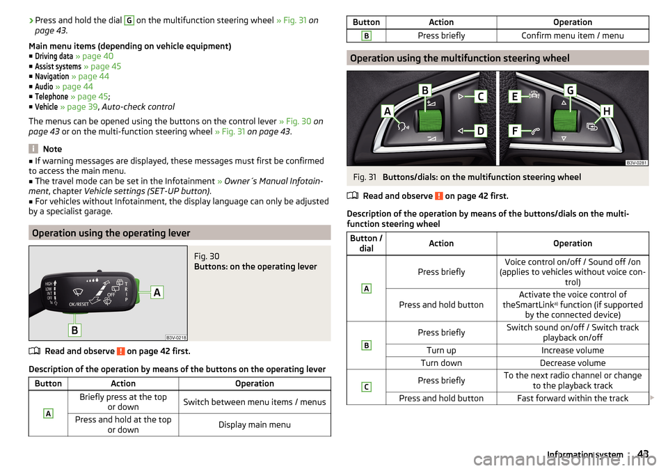
The menus can be opened using the buttons on the control lever » Fig. 30 on
page 43 or on the multi-function steering wheel » Fig. 31 on page 43 .
Note
■
If warning messages are displayed, these messages must first be confirmed
to access the main menu.■
The travel mode can be set in the Infotainment » Owner´s Manual Infotain-
ment , chapter Vehicle settings (SET-UP button) .
■
For vehicles without Infotainment, the display language can only be adjusted
by a specialist garage.
Operation using the operating lever
Fig. 30
Buttons: on the operating lever
Read and observe on page 42 first.
Description of the operation by means of the buttons on the operating lever
ButtonActionOperationABriefly press at the top or downSwitch between menu items / menusPress and hold at the top or downDisplay main menuButtonActionOperationBPress brieflyConfirm menu item / menu
Operation using the multifunction steering wheel
Fig. 31
Buttons/dials: on the multifunction steering wheel
Read and observe
on page 42 first.
Description of the operation by means of the buttons/dials on the multi-
function steering wheel
Button / dialActionOperationA
Press brieflyVoice control on/off / Sound off /on
(applies to vehicles without voice con- trol)Press and hold buttonActivate the voice control of
theSmartLink a)
function (if supported
by the connected device)BPress brieflySwitch sound on/off / Switch track playback on/offTurn upIncrease volumeTurn downDecrease volumeCPress brieflyTo the next radio channel or changeto the playback trackPress and hold buttonFast forward within the track 43Information system
Page 58 of 208

Window operations
Introduction
This chapter contains information on the following subjects:
Mechanical window lefter
56
Electric WindowsElectric Windows
56
Opening the windows in the front passenger door and in the rear doors
57
Force limit
58
Operational faults
58
The window can be operated mechanically by means of the handle attached to
the respective door panel.
Depending on equipment the windows can be operated electrically from the
following locations; the window in the front doors or all windows from the
driver's seat and also via the buttons for the windows in the passenger door or
the rear doors.
WARNINGThe windows should nevertheless be closed carefully – risk of injury!
CAUTION
■ In the event that the windows are frozen, first of all eliminate the ice
» page 136 , Windows and external mirrors and only then operate the electri-
cal power windows. Otherwise, the window sealing and the electrical power
window mechanism could be damaged.■
Make sure that the windows are closed whenever you leave the locked vehi-
cle.
For the sake of the environment
At high speeds you should keep the windows closed to prevent unnecessarily high fuel consumption.
Note
When driving always use the existing heating, air conditioning and ventilation
system for ventilating the interior of the vehicle. If the windows are opened,
dust as well as other dirt can get into the vehicle and in addition the wind
noise is more at certain speeds.Mechanical window lefterFig. 43
Window operation: left/right
Read and observe
and on page 56 first.
Using the respective window crank only one window can be operated mechan-
ically.
Opening
›
Lift the crank in the direction of arrow
A
» Fig. 43 .
Closing
›
Turn the crank in the direction of the arrow
B
» Fig. 43 .
Electric WindowsElectric Windows
Fig. 44
Buttons for window-openers: Version 1/version 2
Read and observe
and on page 56 first.
The electrical power windows can only be operated when the ignition is
switched on.
56Using the system
Page 59 of 208
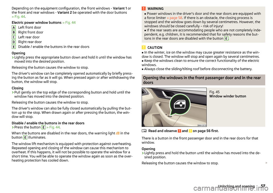
Depending on the equipment configuration, the front windows - Variant 1 or
the front and rear windows - Variant 2 be operated with the door buttons
» Fig. 44 .
Electric power window buttons » Fig. 44
Left front door
Right front door
Left rear door
Right rear door
Disable / enable the buttons in the rear doors
Opening›
Lightly press the appropriate button down and hold it until the window has
moved into the desired position.
Releasing the button causes the window to stop.
The driver's window can be completely opened automatically by briefly press-
ing the button as far as it will go. When pressed again or after withdrawing the
button, the window will stop.
Closing
›
Pull gently on the top edge of the corresponding button and hold until the
window has moved into the desired position.
Releasing the button causes the window to stop.
The driver's window can also be fully closed automatically by pulling the but-
ton up to the stop. When drawn again or after pressing the button, the win-
dow will stop.
Disable / enable the buttons in the rear doors
›
Press the button
E
» Fig. 44 .
When the buttons are disabled in the rear doors, the warning light in the
button
E
illuminates.
The window lift mechanism is equipped with protection against overheating.
Repeated opening and closing of the window can cause this mechanism to
overheat. If this happens, it will not be possible to operate the window for a
short time. You will be able to operate the window again as soon as the over-
heating protection has cooled down.
ABCDEWARNING■ Power windows in the driver's door and the rear doors are equipped with
a force limiter » page 58. If there is an obstacle, the closing process is
stopped and the window goes down by several centimetres. However, the
windows should be closed carefully – risk of injury!■
If the rear seats are accommodating people who are not completely inde-
pendent, e.g. children, it is recommended that for safety reasons the but-
tons in the rear doors are disabled with the button
E
.
CAUTION
■ In the winter, ice on the window may cause greater resistance as the win-
dow is closed. The window will stop and open again by several centimetres.■
Keep the windows clean to ensure the correct functionality of the electric
windows.
■
Always close the sliding/tilting roof before disconnecting the battery.
Opening the windows in the front passenger door and in the rear
doors
Fig. 45
Window winder button
Read and observe and on page 56 first.
There is a button in the front passenger door and in the rear doors for that
window.
Opening
›
Lightly press and hold the button until the window has moved into the de-
sired position.
Releasing the button causes the window to stop.
57Unlocking and opening
Page 72 of 208

Headrests - removing and installingFig. 61
Front head restraints: removal/installation
Fig. 62
Rear head restraints: removal/installation
Read and observe
on page 69 first.
Front restraint
›
Pull the restraint out of the seat backrest as far as the stop.
›
Press locking button
A
in the direction of arrow
1,
and pull out the head re-
straint in the direction of arrow
2
» Fig. 61 .
›
To re-insert the head restraint, push it far enough down into the seat back-
rest in the direction of arrow
3
until the locking button clicks into place.
Rear restraint
›
Pull the restraint out of the seat backrest as far as the stop.
›
Press locking button
B
in the direction of arrow
4
, while at the same time
using a flat-headed screwdriver with a max. width of 5 mm to press the lock-
ing button in opening
C
in the direction of arrow
5
» Fig. 62 .
›
Remove the restraint in the direction of arrow
6
.
›To re-insert the head restraint, push it far enough down into the seat back-
rest in the direction of arrow 7 until the locking button clicks into place.WARNINGPlease note the following points about the head restraint settings » page 8 , Correct and safe seated position .
CAUTION
Store the head restraints that were removed in such a way that they are not
damaged or soiled.
Note
In sports seats, the head restraints are integrated into the seat backrests and
cannot be removed.
Seat features
Introduction
This chapter contains information on the following subjects:
Front seat heating
70
Front armrest setting
71
Rear armrest setting
71
Seat backrests
72
Front seat heating
Fig. 63
Buttons for heating the front
seats
The seat backrests and seats can be heated electrically.
The heat output can be adjusted with the ignition on.
The heater is turned on after the engine has started.
70Using the system
Page 73 of 208

Buttons for the seat heating » Fig. 63
Left seat heating
Right seat heating
Switching on›
Press button
or
» Fig. 63 .
Pressing once switches the seat heating on at its maximum level - Level 2.
With repeated pressing of the switch, the intensity of the heating is reduced
until it is switched off.
The level of the seat heating is indicated by the number of illuminated warning
lights in the switch.
WARNINGIf you have a subdued pain and/or temperature sensitivity, e.g. through
medication, paralysis or because of chronic illness (e.g. diabetes), we rec-
ommend not to use the seat heating. There may be difficult to heal burns. If
the seat heating is used, we recommend to make regular breaks in your
journey when driving long distances, so that the body can recuperate from
the stress of the journey. Please consult your doctor, who can evaluate
your specific condition.
CAUTION
The following instructions must be observed to avoid damage to the seats.■Do not kneel on the seats or otherwise apply concentrated pressure to them.■
Do not turn on any of the seat heaters if seats are not occupied.
■
Do not switch on the relevant seat heating if the seats have objects attached
to or placed on them, for example a child seat, a bag, etc.
■
When there are additional protective covers or protective covers mounted on
each of the seats, do not turn the seat heating on.
Note
■ If the heaters for the rear seats are set to their highest intensity - level 2,
they are automatically switched down to level 1 after 10 minutes.■
If the on-board voltage decreases, the seat heating switches off automati-
cally » page 153 , Automatic load deactivation .
Front armrest settingFig. 64
Raise armrest
The armrest is adjustable in height.
Raise
›
Lift the armrest in the direction of arrow into one of the five locking positions
» Fig. 64 .
Folding down
›
Raise the armrest in the direction of the arrow until it stops » Fig. 64.
›
Fold down the rear armrest.
Rear armrest setting
Fig. 65
Fold down armrest
The armrest can be folded down to increase comfort.
Lowering / raising
›
Pull on the loop
A
and fold down the armrest forward in the direction of the
arrow » Fig. 65 .
Raising takes place in reverse order.
71Seats and head restraints
Page 94 of 208
NoteDuring operation of the manual air conditioning, an increase in engine idle
speed may occur under certain circumstances in order to ensure sufficient
heating comfort.
Climatronic (automatic air conditioning)
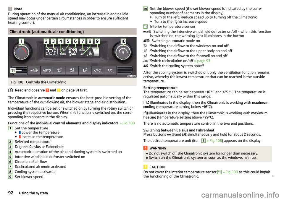
Fig. 108
Controls the Climatronic
Read and observe
and on page 91 first.
The Climatronic in automatic mode ensures the best-possible setting of the
temperature of the out-flowing air, the blower stage and air distribution.
Individual functions can be set or switched on by turning the rotary switch or
pressing the respective button. When this function is switched on, the corre-
sponding icon appears in the display.
Functions of the individual control elements and display indicators » Fig. 108
Set the temperature
▶ Lower the temperature
▶ Increase the temperature
Selected temperature
Degrees Celsius or Fahrenheit
Automatic operation of the air conditioning system is switched on
Intensive windshield defroster switched on
Direction of air flow
Recirculated air mode activated
Cooling system activated
Set blower speed
123456789Set the blower speed (the set blower speed is indicated by the corre-
sponding number of segments in the display)
▶ Turn to the left: Reduce speed up to turning off the Climatronic
▶ Turn to the right: Increase speed
Interior temperature sensor Switching the intensive windshield defroster on/off - when this function
is switched on, the warning light illuminates in the button
Switching automatic mode on
Switching the airflow to the windows on and off
Switching the airflow to the upper body on and off
Switching the airflow to the footwell on and off
Switch recirculation on/off » page 93
Switch the cooling system on/off
After the cooling system is switched off, only the ventilation function remains active, whereby the lowest temperature that can be reached is the outside
temperature.
Setting temperature
The temperature can be set between +16 °C and +29 °C. The temperature is
regulated automatically within this range.
If illuminates in the display, then the Climatronic is working with
maximum
cooling (temperature setting below +16°C).
If illuminates in the display, then the Climatronic is working with
maximum
heating (temperature setting above +29°C).
There is no automatic temperature control in the two end positions.
Switching between Celsius and Fahrenheit
Press buttons and
simultaneously and hold for about 2 seconds.
The desired temperature unit (item 3
» Fig. 108 ) appears on the display.
WARNING■
Do not switch off the Climatronic system for longer than necessary.■Switch on the Climatronic system as soon as the windows mist up.
CAUTION
Do not cover the interior temperature sensor 11 » Fig. 108 as this could impair
the functioning of the Climatronic. 101192Using the system
Page 95 of 208
Note■As soon as the windscreen mists up, press the symbol button . Press the
button once the windscreen has demisted.■
During operation of the Climatronic, an increase in engine idle speed can oc-
cur under certain circumstances in order to ensure adequate heating comfort.
Climatronic - automatic mode
Read and observe
and on page 91 first.
The automatic mode is used in order to maintain a constant temperature andto demist the windows in the interior of the car.
To switch on press the
button. The display shows
(pos.
4
» Fig. 108
on page 92 ).
Automatic mode can be switched off by pressing one of the buttons for the air
distribution or by increasing/decreasing the blower speed. The temperature is
nevertheless regulated.
Air distribution control
Read and observe
and on page 91 first.
The recirculation mode prevents contaminated outside air getting into the In-terior of the vehicle.
In recirculated air mode air is sucked out of the interior of the vehicle and then
fed back into the interior.
Switching on/off
›
Press the button.
Heating and manual air conditioning system
If the air distribution control is set to position when the recirculation modes
is switched on, the recirculated-air mode is switched off. Recirculated air mode
can be switched on again from this setting by repeatedly pressing the symbol
button .
Climatronic
With the recirculated-air mode switched on the symbol appears in the dis-
play.
The symbol disappears from the display after turning off the air recircula-
tion.
Depending on the moisture conditions in the vehicle interior the air recircula-
tion may shut-down automatically.WARNINGThe recirculation system cannot be switched on for a longer period of time,
because there is no supply of fresh air from the outside. “Stale air” may re-
sult in fatigue in the driver and occupants, reduce attention levels and also
cause the windows to mist up. The risk of having an accident increases.
Switch off recirculated air mode as soon as the windows start to mist up.
CAUTION
We recommend not smoking in the vehicle when the recirculating air operation
is switched on. The smoke sucked from inside the vehicle is deposited on the
evaporator of the air conditioner. This produces a permanent odour when the
air conditioning system is operating which can only be eliminated through con-
siderable effort and expense (replacement of compressor).
Note
If recirculated air mode is switched on for around 15 minutes, the symbol
will begin to flash in the Climatronic display as a sign that the recirculated air
mode is switched on long-term. If the recirculated air mode is not switched off,
the symbol flashes for around 5 minutes.93Heating and ventilation
Page 120 of 208

Automatic Braking
If the driver fails to respond to the acute warning, the system starts to apply
the brakes automatically with increasing stopping power in several stages.
Brake assist
If the driver brakes inadequate with an impending collision, the system auto-
matically increases braking force.
The braking assistance only occurs as long as the brake pedal is being firmly
pressed down.
Note
■ If an automatic brake intervention is triggered by the system, the pressure in
the brake system increases and the brake pedal cannot be operated with the
normal pedal stroke.■
The automatic braking interventions can be cancelled by pressing the accel-
erator pedal or by steering intervention.
Disable/enable
Fig. 134
Buttons/dial: on the control lever/on the multifunction steering
wheel
Read and observe
and on page 116 first.
The system is automatically activated each time the ignition is switched on.
The system should only be disabled in exceptional cases »
.
On vehicles with the MAXI DOT display, the system can be activated / deactiva-
ted in the main menu in menu item
Assist systems
» page 42 .
Deactivation / activation in vehicles with segment displayButton
» Fig. 134ActionOperationAPress and hold at the top or downShow Front Assist menu itemBPress brieflyConfirm entry (disable / enable)
Deactivation / activation in vehicles with multi-function steering wheel
Button /dial
» Fig. 134ActionOperation
CPress brieflyShow Front Assist menu itemDPress brieflyConfirm entry (disable / enable)
Disable / enable and setting in the Infotainment
In the Infotainment the entire system or the functions warning and distance warning can be disabled / enabled » Owner´s Manual Infotainment , chap-
ter CAR - Vehicle Settings .
f the distance-warning function was deactivated before the ignition was
switched off, it remains deactivated after the ignition is switched on again.
WARNINGIn the following situations, Front Assist should be switched off for safety
reasons.■
When the vehicle is being towed away.
■
When the vehicle is on a rolling test bench.
■
If an unfounded warning or a system action was taken.
■
When on a truck, or a car ferry service or similar.
Information messages
Read and observe
and on page 116 first.
The warning symbols are shown in the instrument cluster display.
Front Assist: no sensor view.FRONT ASSIST NO SENSOR VIEW
The sensor is soiled or covered.
118Driving