fuel SKODA RAPID SPACEBACK 2015 1.G Owner's Manual
[x] Cancel search | Manufacturer: SKODA, Model Year: 2015, Model line: RAPID SPACEBACK, Model: SKODA RAPID SPACEBACK 2015 1.GPages: 208, PDF Size: 29.2 MB
Page 4 of 208
Table of Contents
Board literature4
Notes
5
Structure and more information about the
Owner´s Manual
6
Abbreviations
Safety
Passive Safety
8
General information
8
Correct and safe seated position
8
Seat belts
11
Using seat belts
11
Inertia reels and belt tensioners
13
Airbag system
14
Description of the airbag system
14
Airbag overview
15
Deactivating airbags
18
Transporting children safely
19
Child seat
19
Fastening systems
22
Using the system
Cockpit
27
Overview
26
Instruments and Indicator Lights
28
Instrument cluster
28
Indicator lights
31
Information system
39
Driver information system
39
Driving data (Multifunction display)
40
MAXI DOT display
42Service interval display46SmartGate47
Unlocking and opening
49
Unlocking and locking
49
Anti-theft alarm system
54
Luggage compartment lid
55
Window operations
56
Lights and visibility
59
Lights
59
Interior lighting
63
Visibility
64
Windscreen wipers and washers
65
Rear mirror
67
Seats and head restraints
69
Seats and head restraints
69
Seat features
70
Transporting and practical equipment
73
Useful equipment
73
Tablet holder
80
Luggage compartment and transport of
cargo
81
Variable loading floor in the luggage
compartment (Estate)
86
Roof rack
89
Heating and ventilation
90
Heating, manual air conditioning system,
Climatronic
90
Driving
Starting-off and Driving
95
Starting and stopping the engine using the
key
95
Starting and stopping the engine at the push
of the button
97
START-STOPsystem
99
Brakes and parking
101Manual gear changing and pedals103Automatic gearbox104
Running-in and economical driving
106
Avoiding damage to your vehicle
108
Assist systems
109
General information
109
Braking and stabilisation systems
109
Parking assistance (ParkPilot)
112
Speed control system
114
Front Assist
116
Fatigue detection
119
Tyre pressure monitoring
119
Hitch and trailer
121
Hitch
121
Trailer
126
General Maintenance
Care and maintenance
130
Service work, adjustments and technical
alterations
130
Washing vehicle
133
Cleaning vehicle exterior
134
Interior care
138
Inspecting and replenishing
140
Fuel
140
Engine compartment
143
Engine oil
146
Coolant
148
Brake fluid
149
Vehicle battery
150
Wheels
154
Tyres and wheel rims
154
Winter operation
1582Table of Contents
Page 9 of 208
AbbreviationsAbbreviationDefinitionrpmEngine revolutions per minuteA2DPa Bluetooth software profile for a one-way transfer of audio
dataABSAnti-lock brake systemAGAutomatic gearboxAGMVehicle battery typeTCSTraction controlCO 2Carbon dioxideCOCDeclaration of conformityDPFDiesel particle filterDSGAutomatic double clutch gearboxEDLElectronic differential lockECEEconomic Commission for EuropeEPCEPC fault lightESCElectronic Stability ControlETRim depthEUEuropean UnionGSMGlobal System for Mobile communicationsHBAHydraulic brake assistHHCUphill start assistKESSYKeyless unlocking, starting and lockingkWKilowatt, measuring unit for outputLEDLighting element typeMCBMulti-collision brakeMDIInputs for connecting external devicesMFDMultifunction displayMGManual gearboxMPIGasoline engine with a multi-point fuel injectionN1Panel van intended exclusively or mainly for the transporta-
tion of goodsAbbreviationDefinitionNmNewton meter, measuring unit for the engine torquePINpersonal identification numberSIM carda card for the identification of the mobile network operatorTDI CRDiesel engine with turbo charging and common rail injection
systemTSATrailer stabilisationTSIPetrol engine with turbo charging and direct injectionVINVehicle identification numberWWatt, unit of powerWi-Fiwireless data network7Abbreviations
Page 17 of 208
System descriptionRead and observe
on page 14 first.
The inflation of the airbag is carried out in a fraction of a second.
When the airbags are deployed, they fill with gas and inflate.
A grey white or red, non-harmful gas is released when the airbag is inflated.
This is perfectly normal and is not an indication of a fire in the vehicle.
Depending on the vehicle equipment, the airbag system consists of the
following parts. ▶ Front airbag for the driver and the front passenger » page 15.
▶ Side airbags » page 16.
▶ Head airbags » page 17.
▶ Airbag warning light in the instrument cluster » page 34.
▶ Key switch for the front passenger airbag » page 18.
▶ Warning light for the front passenger airbag in the middle of the dash panel
» page 18 .
Airbag deployment
Read and observe
on page 14 first.
The airbag system is only functional when the ignition is switched on.
Triggering conditions
It is not possible to generally determine which deployment conditions apply to
the airbag system in every situation. An important role is played by factors
such as the type of object that the vehicle hits (hard/soft), the impact angle, vehicle speed etc.
A decisive factor for the deployment of the airbags is the deceleration which
occurs. If the vehicle deceleration which occurs and is measured during the
collision remains below the prescribed reference values specified in the control
unit, the airbags are not deployed although the vehicle may well suffer severe
damage to the bodywork as a consequence of the accident.
The following airbags will be deployed in the event of a severe frontal
collision.
▶ Driver’s front airbag.
▶ Front passenger airbag.
The following airbags will be deployed in the event of a severe side collision.
▶ Front side airbag on the side of the accident.
▶ Head airbags on the side of the accident.
When an airbag is deployed, the following events occur.
▶ The interior light comes on (if the automatic operation of the interior light is
switched on - switch
).
▶ The hazard warning lights are switched on.
▶ All the doors are unlocked.
▶ The fuel supply to the engine is interrupted.
When there is no air bag deployment?
With minor frontal and side collisions, rear collision, overturning of the vehicle
or vehicle roll-over there is no airbag deployment.
Airbag overview
Introduction
This chapter contains information on the following subjects:
Front airbags
15
Side airbags
16
Head airbags
17
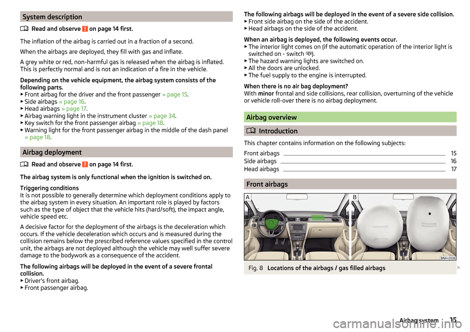
Front airbags
Fig. 8
Locations of the airbags / gas filled airbags
15Airbag system
Page 30 of 208
Instruments and Indicator Lights
Instrument cluster
Introduction
This chapter contains information on the following subjects:
Overview
28
Revolution counter
29
Display
29
Coolant temperature gauge
29
Fuel gauge
30
Counter for distance driven
30
Setting the clock
31
The instrument cluster gives the driver basic information such as the current
speed, engine speed, the state of some vehicle systems and the like.
If there is a fault in the instrument cluster, the following message will appear
in the display.
Error: instrument cluster. Workshop!COMBI-INSTRUM_ WORKSHOP
Seek help from a specialist garage.
WARNINGConcentrate fully at all times on your driving! As the driver you are fully re-
sponsible for road safety.
Note
■ If the message SAFE CP appears in the instrument cluster display, the compo-
nent protection for the instrument cluster is active. Further information
» page 132 , Component protection .■
With the ignition switched on the instruments are also illuminated. The
brightness of the instrument illumination is set automatically depending on
the ambient lighting throughout.
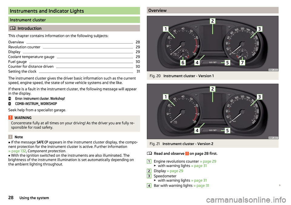
OverviewFig. 20
Instrument cluster - Version 1
Fig. 21
Instrument cluster - Version 2
Read and observe
on page 28 first.
Engine revolutions counter » page 29
▶ with warning lights » page 31
Display » page 29
Speedometer
▶ with warning lights » page 31
Bar with warning lights » page 31
123428Using the system
Page 31 of 208
Button for:
▶ Setting the time » page 31
▶ Reset counter for distance travelled (trip) » page 30
▶ Displaying the distance and days until the next service interval
» page 46
Coolant temperature gauge » page 29
Fuel gauge » page 30
Revolution counter
Read and observe
on page 28 first.
The tachometer
1
» Fig. 20 on page 28 or » Fig. 21 on page 28 shows the ac-
tual engine speed per minute.
The beginning of the red scale range of the tachometer indicates the maxi-
mum permitted engine speed of a driven-in and operating warm engine.
You should shift into the next highest gear before the red scale of the revolu- tion counter is reached, or select mode D on the automatic gearbox.
The gear recommendation is important to note in order to maintain the opti-
mum engine speed » page 39.
CAUTION
The pointer of the tachometer must reach the red area for only a short time -
there is a risk of engine damage!
Display
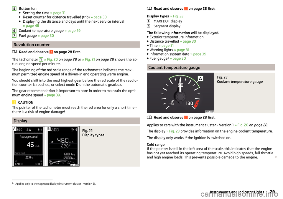
Fig. 22
Display types
567Read and observe on page 28 first.
Display types » Fig. 22
MAXI DOT display
Segment display
The following information will be displayed.
▶ Exterior temperature information
▶ Distance travelled » page 30
▶ Time » page 31
▶ Warning lights » page 31
▶ Information system data » page 39
▶ Fuel gauge 1)
» page 30
Coolant temperature gauge
Fig. 23
Coolant temperature gauge
Read and observe on page 28 first.
Applies to cars with the instrument cluster - Version 1 » Fig. 20 on page 28 .
The display » Fig. 23 provides information on the engine coolant temperature.
The display only works if the ignition is switched on.
Cold range
If the pointer is still in the left area of the scale, this indicates that the engine
has not yet reached its operating temperature. Avoid high speeds, full throttle
and high engine loads. This prevents possible damage to the engine.
1)
Applies only to the segment display (instrument cluster - version 2).
29Instruments and Indicator Lights
Page 32 of 208
The operating range
The engine has reached its operating temperature as soon as the pointer
moves into the middle of the scale A
» Fig. 23 .
High temperature range
If the pointer reaches the red area of the scale, the coolant temperature is too
high.
CAUTION
■ Additional headlights and other attached components in front of the air inlet
impair the cooling efficiency of the coolant.■
Never cover the radiator - there is a risk of the engine overheating.
Note
On vehicles with the multifunction display, the coolant temperature can be
shown on the display by the corresponding driving data entry being selected
» page 40 , Information overview .
Fuel gauge
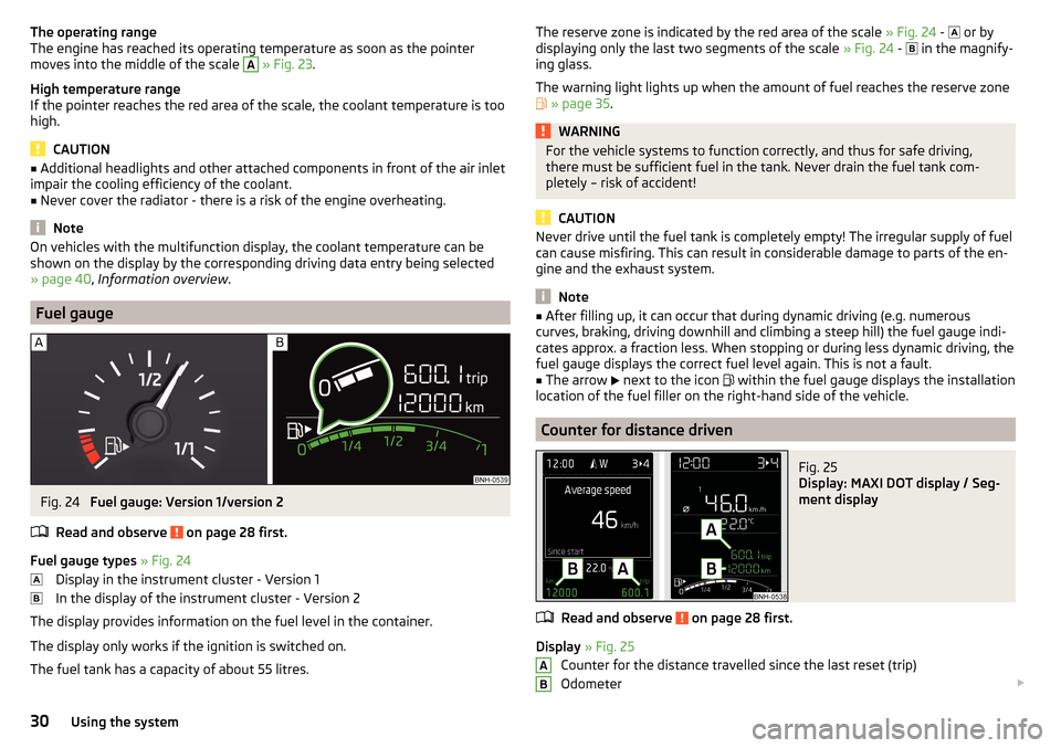
Fig. 24
Fuel gauge: Version 1/version 2
Read and observe
on page 28 first.
Fuel gauge types » Fig. 24
Display in the instrument cluster - Version 1
In the display of the instrument cluster - Version 2
The display provides information on the fuel level in the container.
The display only works if the ignition is switched on.
The fuel tank has a capacity of about 55 litres.
The reserve zone is indicated by the red area of the scale » Fig. 24 - or by
displaying only the last two segments of the scale » Fig. 24 - in the magnify-
ing glass.
The warning light lights up when the amount of fuel reaches the reserve zone
» page 35 .WARNINGFor the vehicle systems to function correctly, and thus for safe driving,
there must be sufficient fuel in the tank. Never drain the fuel tank com-
pletely – risk of accident!
CAUTION
Never drive until the fuel tank is completely empty! The irregular supply of fuel
can cause misfiring. This can result in considerable damage to parts of the en-
gine and the exhaust system.
Note
■ After filling up, it can occur that during dynamic driving (e.g. numerous
curves, braking, driving downhill and climbing a steep hill) the fuel gauge indi-
cates approx. a fraction less. When stopping or during less dynamic driving, the
fuel gauge displays the correct fuel level again. This is not a fault.■
The arrow
next to the icon
within the fuel gauge displays the installation
location of the fuel filler on the right-hand side of the vehicle.
Counter for distance driven
Fig. 25
Display: MAXI DOT display / Seg-
ment display
Read and observe on page 28 first.
Display » Fig. 25
Counter for the distance travelled since the last reset (trip)
Odometer
AB30Using the system
Page 33 of 208
Reset counter for distance travelled (trip)›Press button A » Fig. 26 on page 31 .
Setting the clock
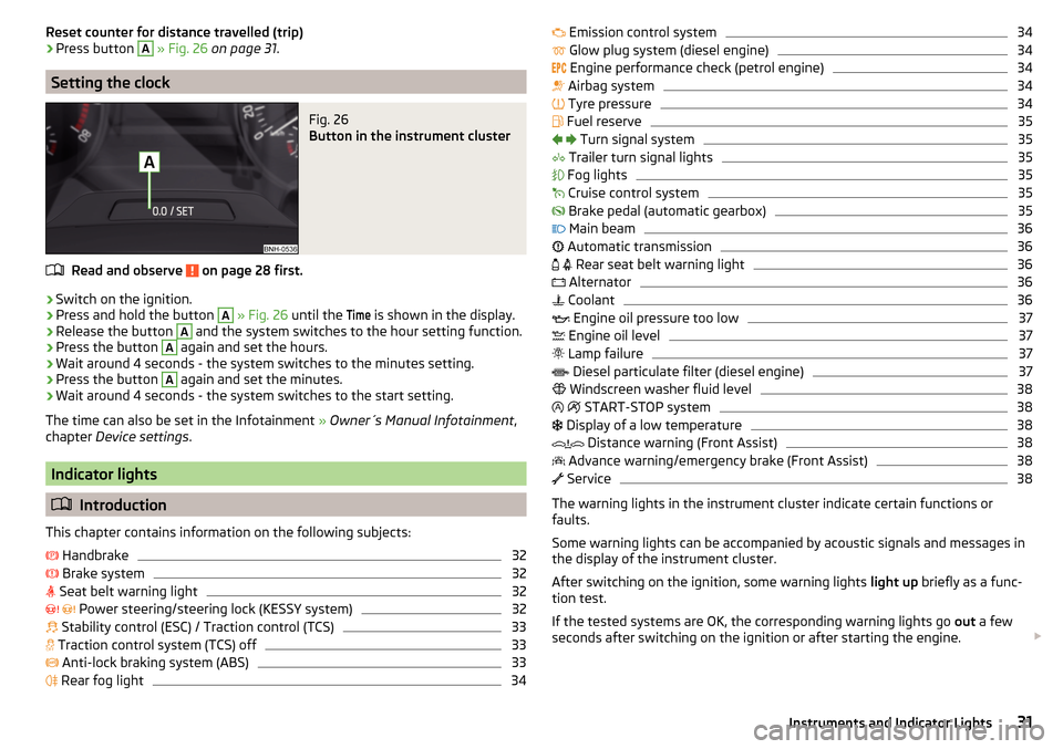
Fig. 26
Button in the instrument cluster
Read and observe on page 28 first.
›
Switch on the ignition.
›
Press and hold the button
A
» Fig. 26 until the
Time
is shown in the display.
›
Release the button
A
and the system switches to the hour setting function.
›
Press the button
A
again and set the hours.
›
Wait around 4 seconds - the system switches to the minutes setting.
›
Press the button
A
again and set the minutes.
›
Wait around 4 seconds - the system switches to the start setting.
The time can also be set in the Infotainment » Owner´s Manual Infotainment ,
chapter Device settings .
Indicator lights
Introduction
This chapter contains information on the following subjects:
Handbrake
32
Brake system
32
Seat belt warning light
32
Power steering/steering lock (KESSY system)
32
Stability control (ESC) / Traction control (TCS)
33
Traction control system (TCS) off
33
Anti-lock braking system (ABS)
33
Rear fog light
34
Emission control system34 Glow plug system (diesel engine)34
Engine performance check (petrol engine)
34
Airbag system
34
Tyre pressure
34
Fuel reserve
35
Turn signal system
35
Trailer turn signal lights
35
Fog lights
35
Cruise control system
35
Brake pedal (automatic gearbox)
35
Main beam
36
Automatic transmission
36
Rear seat belt warning light
36
Alternator
36
Coolant
36
Engine oil pressure too low
37
Engine oil level
37
Lamp failure
37
Diesel particulate filter (diesel engine)
37
Windscreen washer fluid level
38
START-STOP system
38
Display of a low temperature
38
Distance warning (Front Assist)
38
Advance warning/emergency brake (Front Assist)
38
Service
38
The warning lights in the instrument cluster indicate certain functions or
faults.
Some warning lights can be accompanied by acoustic signals and messages in
the display of the instrument cluster.
After switching on the ignition, some warning lights light up briefly as a func-
tion test.
If the tested systems are OK, the corresponding warning lights go out a few
seconds after switching on the ignition or after starting the engine.
31Instruments and Indicator Lights
Page 37 of 208
If the warning light flashes after starting the engine again, there is a system
error.
Seek help from a specialist garage.
Disconnecting the vehicle battery
If the vehicle's battery has been disconnected and reconnected, the indicator
light
comes on after switching on the ignition.
The warning light should go out after driving a short distance.
If, after a short drive, the indicator light does not go out, there is a system er-
ror.
Seek help from a specialist garage.
Other incidents
The illumination of the warning light can have the following reasons.
▶ The vehicle is loaded on one side. Distribute loads as evenly as possible.
▶ The wheels of one axle are loaded more heavily (e.g. when towing a trailer or
when driving uphill or downhill).
▶ Snow chains are mounted.
▶ A wheel has been changed.
CAUTION
Under certain circumstances (e.g. sporty style of driving, wintry or unpaved
roads) the warning light in the instrument cluster may be delayed or not
light up at all.
Fuel reserve
Read and observe
on page 32 first.
illuminates – the fuel level in the fuel tank is at the reserve level (approxi-
mately 7 litres).
Please refuel. Range: ...
kmPLEASE REFUEL RANGE …
km
An audible signal sounds as a warning.
Note
The text in the display goes out after refuelling and driving a short distance. Turn signal system
Read and observe
on page 32 first.
flashes – the left turn signal is switched on.
flashes – the right turn signal is switched on.
If there is a fault in the turn signal system, the warning light flashes at twice
its normal rate. This does not apply when towing a trailer.
When the hazard warning light system is switched on, this will cause all of the
turn signal lights as well as both warning lights to flash.
Trailer turn signal lights
Read and observe
on page 32 first.
flashes – the trailer turn signal lights are switched on.
If a trailer is hitched and the warning light is not flashing, one of the trailer
turn signal lights has failed.
An example message in the display of the instrument cluster
Trailer: check left turn signal!TRAILER TURN SIG_ CHECK LEFT
Check the trailer bulbs.
Fog lights
Read and observe
on page 32 first.
illuminates – the fog lights are switched on.
Cruise control system
Read and observe
on page 32 first.
illuminates – the vehicle speed is regulated by the cruise control system.
Brake pedal (automatic gearbox)
Read and observe
on page 32 first.
illuminates – apply the brake.
35Instruments and Indicator Lights
Page 40 of 208

WARNING■Always adjust the speed and driving style to the actual weather, road, ter-
rain and traffic conditions.■
The diesel particulate filter reaches very high temperatures - there is a
fire hazard and serious injury could be caused. Therefore, never stop the
vehicle at places where the underside of your vehicle can come into contact
with flammable materials such as dry grass, undergrowth, leaves, spilled
fuel or such like.
CAUTION
■ As long as the warning light illuminates, one must take into account an
increased fuel consumption and a power reduction of the engine.■
Using diesel fuel with increased sulphur content can significantly reduce the
service life of the diesel particle filter. A ŠKODA Partner will be able to tell you
which countries use diesel fuel with increased sulphur content.
Note
We encourage you to avoid constant short journeys. This will improve the com-
bustion process of the soot particles in the diesel particulate filter.
Windscreen washer fluid level
Read and observe
on page 32 first.
illuminates – the windscreen washer fluid level is too low.
Add washer fluid!WASHER FLUID PLEASE TOP UP›
Fill up the windscreen washer fluid.
START-STOP system
Read and observe
on page 32 first.
The warning lights
indicates the state of the START STOP system
» page 99 , START-STOPsystem .
Display of a low temperature
Read and observe
on page 32 first.
illuminates – the outside temperature is below +4 °C.
WARNINGEven at temperatures of around +4 °C, black ice may still be on the road
surface! You should therefore not only rely on the outside temperature dis- play for accurate information as to whether there is ice on the road.
Distance warning (Front Assist)
Read and observe
on page 32 first.
illuminates – the safe distance to the vehicle in front is below the mini-
mum.
The warning light is only shown in the MAXI DOTdisplay.
Information on the Front Assist system » page 116.
Advance warning/emergency brake (Front Assist)
Read and observe
on page 32 first.
illuminates – the system has recognized the risk of a collision or automati-
cally triggered an emergency braking manoeuvre.
Information on the Front Assist system » page 116.
Service
Read and observe
on page 32 first.
illuminates – message regarding a due service appointment
» page 46,
Service interval display .
38Using the system
Page 41 of 208

Information system
Driver information system
Introduction
This chapter contains information on the following subjects:
Door, luggage compartment or bonnet warning
39
Overspeed warning at 120 km/h
39
Auto-check control
39
Gear recommendation
39
Depending on the vehicle's equipment, the information system vie the display
of the instrument cluster provides the following information.
▶ Driving data (multifunction display) » page 40.
▶ Data relating to the Maxi DOT display » page 42.
▶ Service interval display » page 46.
▶ Selector lever positions for an automatic gearbox » page 104.
▶ Information and alerts in the Assist systems » page 109.
WARNINGConcentrate fully at all times on your driving! As the driver you are fully re-
sponsible for the operation of your vehicle.
Door, luggage compartment or bonnet warning
Read and observe
on page 39 first.
If at least one door is open, or the boot or bonnet is open, the display indicates
the relevant open door or boot/bonnet.
An acoustic signal will also sound if you drive the vehicle above 6 km/h when a
door is open.
Overspeed warning at 120 km/h
Read and observe
on page 39 first.
This function only applies to certain countries.
An audible warning signal will sound when the vehicle speed exceeds 120
km/h. The audible warning signal is switched off when the vehicle speed falls
below 120 km/h.
Auto-check control
Read and observe
on page 39 first.
Certain functions and conditions of individual vehicle systems are checked
continuously when the ignition is switched on.
As long as the faults are not rectified the messages are always shown. After
they are displayed for the first time, the warning lights
(danger) or
(warn-
ing) continue to be indicated without information for the driver.
Gear recommendation
Fig. 27
Information on the selected
gear / Gear recommendation
Read and observe on page 39 first.
A suitable gear is engaged, if necessary, a recommendation to shift to high or
lower gear is displayed.
A suitably engaged gear helps to reduce the fuel consumption and assist the
service life and reliability of the engine.
Display » Fig. 27
Optimal gear engaged
Recommended gear
Recommended gear
Besides showing the engaged gear, the arrow icon and the recommended
gear are displayed.
For instance, if
appears in this display, this means it is recommended that
you shift from gear 3 to gear 4.
39Information system