ECU SKODA RAPID SPACEBACK 2016 1.G User Guide
[x] Cancel search | Manufacturer: SKODA, Model Year: 2016, Model line: RAPID SPACEBACK, Model: SKODA RAPID SPACEBACK 2016 1.GPages: 184, PDF Size: 28.1 MB
Page 68 of 184

›To
remove , hold the locking button A in the direction of arrow 1, at the
same time, using a flat screwdriver (with a max. width of 5 mm), press the
locking button in the opening B
in the direction of arrow
2
and remove the
rest in the direction of arrow
3
» Fig. 60 .
›
To insert the headrest, push the headrest into the seat backrest in the direc-
tion of arrow
4
until the locking button clicks into place.
Seat heaters
Fig. 61
Buttons for heating the front /rear seats
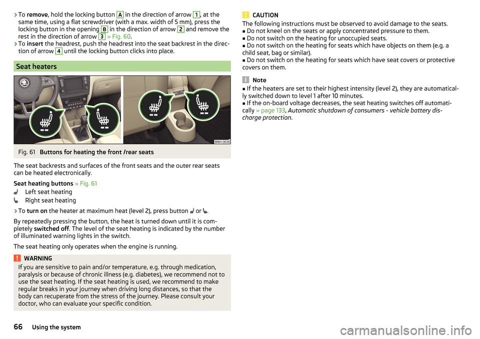
The seat backrests and surfaces of the front seats and the outer rear seats
can be heated electronically.
Seat heating buttons » Fig. 61
Left seat heating
Right seat heating
›
To turn on the heater at maximum heat (level 2), press button
or
.
By repeatedly pressing the button, the heat is turned down until it is com-
pletely switched off . The level of the seat heating is indicated by the number
of illuminated warning lights in the switch.
The seat heating only operates when the engine is running.
WARNINGIf you are sensitive to pain and/or temperature, e.g. through medication,
paralysis or because of chronic illness (e.g. diabetes), we recommend not to
use the seat heating. If the seat heating is used, we recommend to make
regular breaks in your journey when driving long distances, so that the
body can recuperate from the stress of the journey. Please consult your
doctor, who can evaluate your specific condition.CAUTIONThe following instructions must be observed to avoid damage to the seats.■Do not kneel on the seats or apply concentrated pressure to them.■
Do not switch on the heating for unoccupied seats.
■
Do not switch on the heating for seats which have objects on them (e.g. a
child seat, bag or similar).
■
Do not switch on the heating for seats which have seat covers or protective
covers on them.
Note
■ If the heaters are set to their highest intensity (level 2), they are automatical-
ly switched down to level 1 after 10 minutes.■
If the on-board voltage decreases, the seat heating switches off automati-
cally » page 133 , Automatic shutdown of consumers - vehicle battery dis-
charge protection .
66Using the system
Page 76 of 184

The maximum permissible load of each of the pockets is 150 g.
Tablet holder
Introduction
This chapter contains information on the following subjects:
Install / Remove
74
Handling the holder
74
External devices (e.g. tablet, smartphone, etc.) measuring min. 122 mm and
max. 195 mm can be secured in the holder.
The maximum permissible load of the holder is 750 g.
CAUTION
Never exceed the maximum permissible load of the holder - there is a risk of
damage or functional impairment.
Install / Remove
Fig. 82
Inserting: Adapter / holder
Fig. 83
Removing: Adapter / holder
Read and observe
on page 74 first.
›
To insert , attach the opened adapter to the guide rods of the front headrest
and clip in the direction of arrow
1
» Fig. 82 » .
›
Clip the holder into the adapter in the direction of arrow
2
.
›
To remove , pull on the securing tab
A
in direction of arrow
3
and take the
holder in direction of arrow
4
out of the adapter » Fig. 83.
›
Press the adapter and remove it from the guide rods of the head rest in the
direction of arrow
5
.
WARNINGClip in the adapter carefully - there is a risk of injuring your finger.
Handling the holder
Fig. 84
Tilting and rotating the holder
74Using the system
Page 77 of 184

Fig. 85
Adjusting the holder size
Read and observe on page 74 first.
The holder may be tipped by 30° in the direction of the arrow
1
and turned by
360° in the direction of arrow
2
» Fig. 84 .
›
To adjust the holder size , pull out the securing tab
A
in the direction of ar-
row
3
and push the part
B
in the direction of arrow
4
to the desired posi-
tion » Fig. 85 .
Transport of cargo
Luggage compartment and transporting objects
Introduction
This chapter contains information on the following subjects:
Fastening elements
76
Fixing nets
76
Multifunction pocket
77
Hooks
77
Luggage compartment cover
77
“Parking position” of the boot cover
78
Storage compartment in the boot
78
Storage net bag
79
Cargo elements
79
Floor covering on both sides
79
Class N1 vehicles
79
When transporting heavy objects, the driving characteristics change due to the
shift in centre-of-gravity. The speed and style of driving must be adjusted ac-
cordingly.
When transporting cargo the following the instructions must be adhered to
▶ Distribute the load evenly in the luggage compartment and secure it with
suitable lashing straps to the lashing eyes or fixing nets so that they cannot
slip.
▶ Place heavy objects as far forward as possible.
▶ Tyre pressure is to match the load.
In the event of an accident, even small and light objects gain so much kinetic
energy that they can cause severe injuries.
The magnitude of the kinetic energy is dependent on the speed at which the
vehicle is travelling and the weight of the object.
Luggage compartment light
The light switches on/off when the luggage compartment lid is opened or
closed.
If the boot lid is open and the ignition switched off, the light will go out auto-
matically after 10 minutes.
75Transport of cargo
Page 78 of 184

WARNING■Never exceed the maximum permissible load of the respective fasteners,
nets, hooks etc. Heavy objects were not secured sufficiently – risk of injury!■
Do not exceed the permissible axle loads and permissible gross weight of
the vehicle – risk of accident!
■
An unsecured dirt or improperly attached load could slip during a sudden
manoeuvre or in an accident - danger of injury!
■
Loose cargo could hit a deployed airbag and injure occupants – danger of
death!
■
When transporting loads in the luggage compartment that has been en-
larged by folding the rear seats forward, ensure the safety of the passen-
gers transported on the other rear seats .
CAUTION
■ Never exceed the maximum permissible load of the respective fasteners,
nets, hooks etc. - these could be damaged.■
Please ensure that the heating elements for the rear window heater are not
damaged as a result of abrasive objects.
■
Do not place sharp objects in the nets and storage compartments in the lug-
gage compartment - there is a risk of damage to the net as well as the com-
partments.
■
Put the items in the storage compartments carefully and do not put point-
shaped objects - there is a risk of damage to the compartments.
Fastening elements
Fig. 86
Fasteners
Read and observe and on page 76 first.
The fasteners are located on both sides of the luggage compartment.
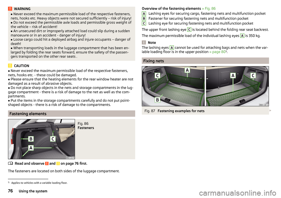
Overview of the fastening elements » Fig. 86
Lashing eyes for securing cargo, fastening nets and multifunction pocket
Fastener for securing fastening nets and multifunction pocket
Lashing eye for securing fastening nets and multifunction pocket
The upper front lashing eye C
is located behind the folding rear seat backrest.
The maximum permissible load of the individual lashing eyes
A
is 350 kg.
Note
The lashing eyes A cannot be used for attaching bags and nets when the var-
iable loading floor is in the upper position » page 801)
.
Fixing nets
Fig. 87
Fastening examples for nets
ABC1)
Applies to vehicles with a variable loading floor.
76Using the system
Page 79 of 184

Fig. 88
Fastening a vertical pocket
Read and observe and on page 76 first.
Fastening examples for nets » Fig. 87 and » Fig. 88
Horizontal pocket
Floor net
Vertical pocket
The maximum permissible load of each of the nets is 1.5 kg.
Multifunction pocket
Fig. 89
Securing the multifunction pock-
et
Read and observe and on page 76 first.
The pocket » Fig. 89 can be secured to the fastening elements
A
,
B
and
C
» Fig. 86 on page 76 .
The maximum permissible load for the pocket attached to the fastening ele-
ment is 3 kg.
Note
In vehicles with a variable loading floor, it is not possible to secure the pocket
to the fastening elements.ABCHooksFig. 90
Hooks
Read and observe and on page 76 first.
One hook for attaching small items of luggage, such as bags etc., is provided
on each side of the luggage compartment » Fig. 90.
The maximum permissible load of the hook is 7.5 kg.
Luggage compartment cover
Fig. 91
Remove the luggage compartment cover
Read and observe
and on page 76 first.
If the support straps
A
» Fig. 91 are attached to the boot lid, then opening the
lid will raise the boot lid cover (hereafter referred to as the cover).
The cover may be removed from the vehicle or stowed behind the rear seat
backs in the so-called “park position” » Fig. 92 on page 78 .
The maximum permissible load of the cover is 1 kg.
77Transport of cargo
Page 81 of 184

Storage net bagFig. 94
Meshed pocket for storage
Read and observe and on page 76 first.
The meshed pocket for storage is located on the right-hand side of the boot» Fig. 94 .
The meshed pocket for storage is designed for storing small objects of up to
1.5 kg. in weight in total.
Cargo elements
Fig. 95
Remove cargo element: Version 1/version 2
Fig. 96
Remove cargo element: Version 3 / Mounting example of the car-
go using the cargo elements
Read and observe
and on page 76 first.
The cargo elements are designed for mounting and securing loads with a max-imum gross weight of 8 kg.
›
To use , remove the cargo elements in the direction of the arrows » Fig. 95
and » Fig. 96
.
›
Use the cargo elements to secure the load as close as possible to the rear
seats » Fig. 96
.
›
After use, secure the cargoelements in their original position.
Floor covering on both sides
Read and observe
and on page 76 first.
You can fit a double-sided floor covering in the luggage compartment. One
side is made of fabric, the other side is washable (suitable for transporting wet
or dirty items).
Class N1 vehicles
Read and observe
and on page 76 first.
In class N1 vehicles that are not fitted with a protective grille, a lashing set that
complies with the EN 12195 standard (1 - 4) must be used for fastening the
load.
79Transport of cargo
Page 83 of 184

CAUTIONWhen removing or inserting the variable loading floor, a distance of 15 cm B» Fig. 98 underneath the edge of the cover must be maintained - risk of dam-
aging the boot lid seal.
Note
The variable loading floor cannot be placed in the vehicle when the luggage
compartment cover is in the “park position” » page 78.
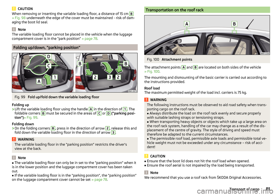
Folding up/down, “parking position”
Fig. 99
Fold up/fold down the variable loading floor
Folding up
›
Lift the variable loading floor using the handle
A
in the direction of
1
. The
foldable corners
B
must be secured in the areas of
C
or
D
(“parking posi-
tion”) » Fig. 99 .
Folding down
›
On the folding corners
B
, press in the direction of arrow
2
, release this and
fold down the variable loading floor in the direction of arrow
3
.
WARNINGThe variable loading floor in the “parking position” restricts the driver's
view at the back.
Note
■ The variable loading floor can only be in set to the “parking position” when it
is in the lower position and the luggage compartment cover has been taken
out.■
If the variable loading floor is in the “parking position”, the “parking position”
on the luggage compartment cover cannot be set » page 78.
Transportation on the roof rackFig. 100
Attachment points
The attachment points
A
and
B
are located on both sides of the vehicle
» Fig. 100 .
The mounting and dismounting of the basic carrier is carried out according to
the instructions provided.
Roof load
The maximum permitted weight of the load incl. carriers is 75 kg.
WARNINGThe following instructions must be observed to aid road safety when trans- porting cargo on the roof rack.■
Always distribute the load on the roof rack evenly and secure properly
with suitable lashing straps or tensioning straps.
■
When transporting heavy objects or objects which take up a large area on
the roof rack system, handling of the car may change as a result of the dis-
placement of the centre of gravity. The style of driving and speed must
therefore be adapted to the current circumstances.
■
The permissible roof load, permissible axle loads and permissible total ve-
hicle weight must not be exceeded under any circumstance – risk of acci-
dent!
CAUTION
■ Ensure that the boot lid does not hit the roof load when opened.■Ensure the roof aerial is not impaired by the load being transported.
Note
We recommend that you use a roof rack from ŠKODA Original Accessories.81Transport of cargo
Page 92 of 184

The wear and tear on the brake pads is dependent on the operating condi-
tions and driving style. In difficult conditions (e.g. urban, sporty driving), the
condition of the brakes should be checked between services by a specialist ga-
rage.
Brake response can be slower if the brakes are covered in moisture or, in win-
ter, have a layer of ice or salt on them . The brakes should be cleaned and
dried by applying the brakes many times over »
.
Corrosion on the brake discs and dirt on the brake pads can occur if the vehicle
has been parked for a long period and if you do not make much use of the
braking system. The brakes are cleaned by applying the brakes several times
over »
.
Before negotiating a long or steep gradient , reduce speed and shift down a
gear. As a result, the braking effect of the engine will be used, reducing the
load on the brakes. If, nevertheless, there is a need for additional braking, it
should be carried out at intervals.
Emergency braking warning - if it is necessary to brake hard, the system may
cause the brake lights to automatically flash, to alert the traffic behind.
New brake pads must first be “run in” because these do not initially have the
best possible braking effect. Drive especially carefully for the first 200 km or
so.
If the brake fluid level is too low, it can cause faults in the braking system ;
the warning light will light up in the instrument cluster
» page 30,
Braking
system . If the warning light does not light up, yet the stopping distance is per-
ceived to be longer than before, the driving style should be adapted in view of
the unknown cause of the problem, and braking kept to a minimum - seek the
help of a specialist garage without delay.
The brake booster increases the pressure generated with the brake pedal. The
brake booster only operates when the engine is running.
WARNING■ Greater physical effort is required for braking when the engine is switch-
ed off – risk of accident!■
The clutch pedal must be actuated when braking on a vehicle with man-
ual transmission, when the vehicle is in gear and at low revs. Otherwise,
the functionality of the brake system may be impaired – risk of accident!
WARNING (Continued)■ Do not depress the brake pedal if there is no requirement to slow down.
This causes the brakes to overheat and can also result in a longer braking
distance and excessive wear - risk of accident!■
Only brake for the purpose of drying and cleaning the brake discs if the
traffic conditions permit this. Do not place any other road users in jeopardy.
■
Recommendations for new brake pads should be followed.
■
When stopping and parking, the parking brake should always be applied
firmly, otherwise the vehicle could move off - risk of accident!
■
If a front spoiler, full wheel trim, etc. is mounted retrospectively, it must
be ensured that the air supply to the front wheel brakes is not reduced.
Otherwise, the front brakes could be in danger of overheating – risk of acci-
dent!
Handbrake
Fig. 108
Handbrake
Read and observe on page 90 first.
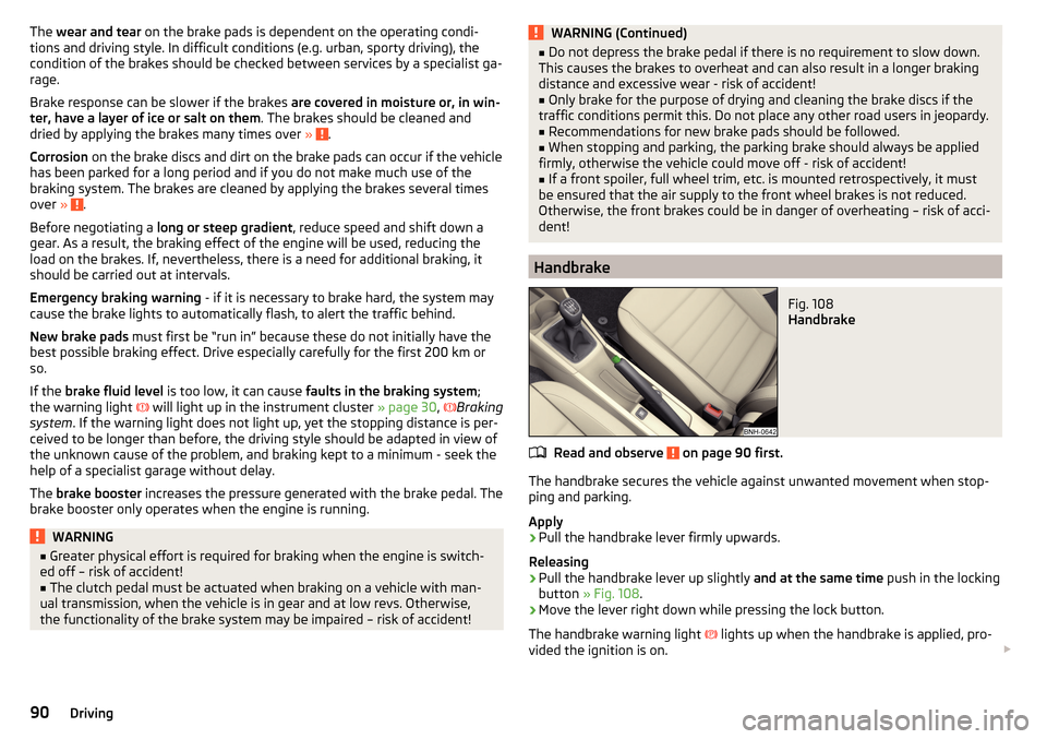
The handbrake secures the vehicle against unwanted movement when stop-
ping and parking.
Apply
›
Pull the handbrake lever firmly upwards.
Releasing
›
Pull the handbrake lever up slightly and at the same time push in the locking
button » Fig. 108 .
›
Move the lever right down while pressing the lock button.
The handbrake warning light
lights up when the handbrake is applied, pro-
vided the ignition is on.
90Driving
Page 94 of 184

Only a floor mat (ex-factory or from the ŠKODA Original Accessories range)
which can be secured to the attachment points should be used in the driver's
footwell.WARNINGThere should be no objects in the driver's footwell, otherwise the pedal op-
eration can be impeded - risk of accident!
Automatic gearbox
Introduction
This chapter contains information on the following subjects:
Select selector lever position
92
Selector lever lock
93
Manual shifting (Tiptronic)
93
Starting-off and driving
94
The automatic transmission performs an automatic gear change irrespective of
the engine load, the operation of the accelerator, the vehicle speed and the
selected driving mode.
The modes of the automatic transmission can be adjusted by the driver by
means of the selector lever.
WARNING■ Do not accelerate when selecting drive mode prior to moving off - risk of
accident!■
Never move the selector lever to mode R or P when driving – risk of acci-
dent!
■
If the vehicle stalls, with engine running, in the D, S , R or Tiptronic mode,
the vehicle must be prevented from rolling away by means of the brake
pedal or the parking brake. Even when the engine is idling, the power
transmission is never completely interrupted – the vehicle crawls forward.
■
When leaving the vehicle, the selector lever must always be set to P. Oth-
erwise, the vehicle could be set in motion - risk of accident.
CAUTION
If you want to move the selector lever from position N to position D / S whilst
driving, the engine must be running at idling speed.Select selector lever positionFig. 110
Selector lever/display
Read and observe and on page 92 first.
The selector lever can be moved by shifting to one of the following positions » Fig. 110 . In some positions you have to push the locking button » page 93.
When the ignition is switched on, the gearbox mode and the currently selected
gear are indicated in the display » Fig. 110.
Parking - the position can be set only when the vehicle is at a standstill.
The drive wheels are mechanically locked.
Reverse gear - the position can only be selected when the vehicle is sta-
tionary and the engine is idling.
Neutral (idle position) - power transmission to the drive wheels is inter-
rupted.
Forward mode / sports programme - the gear change takes place in the
position S at higher engine speeds than in mode D
(Sprung position) - choice between positions D and S
In mode D or S, the forward gears are shifted automatically depending on the
engine load, the operation of the accelerator pedal, the vehicle speed, and the
selected driving mode .
PRND/S92Driving
Page 113 of 184

Towing device and trailer
Hitch
Introduction
This chapter contains information on the following subjects:
Description
111
Adjusting the ready position
112
Check the setting of the standby position
112
Assembling the tow bar – Step 1
113
Assembling the tow bar – Step 2
113
Check proper fitting
114
Removing the tow bar – Step 1
114
Removing the tow bar – Step 2
114
Vertical load with mounted accessories
115
The maximum trailer nose weight when towing a trailer is 50 kg. Other infor-
mation (e.g. on the nameplate of the trailer device) provide only about the test
values of the device information.
WARNING■ Check that the tow bar is seated correctly and is secured in the mounting
recess before the start of every journey.■
When the ball rod is not used and properly secured in the receiving shaft,
this could be damaged or incomplete and must not be used - risk of acci-
dent.
■
Do not modify or adapt the towing device in any way.
■
Keep the mounting recess of the towing equipment clean at all times.
Such dirt prevents the ball head from being attached securely.
DescriptionFig. 135
Carrier for the towing device / tow bar
Read and observe
on page 111 first.
The ball rod is detachable and is located in the stowage compartment for the spare / emergency wheel.
Support for the towing device and tow bar » Fig. 135
Cap
Mounting recess
Protective cap
Locking ball
Centering
Hand wheel
Key
Lock cap
Red marking on the hand wheel
Tow bar
Green marking on the hand wheel
White marking on tow bar
123456789101112111Towing device and trailer