turn signal SKODA RAPID SPACEBACK 2016 1.G User Guide
[x] Cancel search | Manufacturer: SKODA, Model Year: 2016, Model line: RAPID SPACEBACK, Model: SKODA RAPID SPACEBACK 2016 1.GPages: 184, PDF Size: 28.1 MB
Page 57 of 184
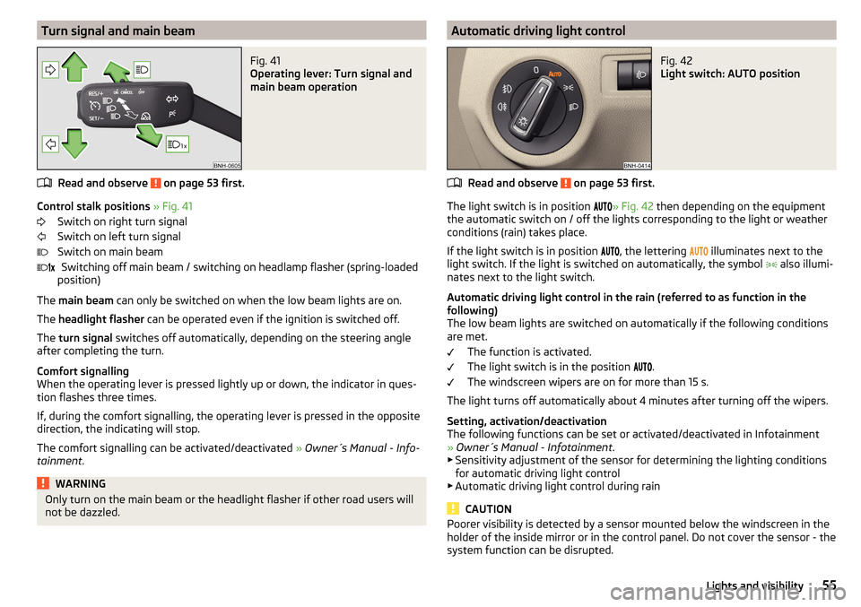
Turn signal and main beamFig. 41
Operating lever: Turn signal and
main beam operation
Read and observe on page 53 first.
Control stalk positions » Fig. 41
Switch on right turn signal
Switch on left turn signal
Switch on main beam Switching off main beam / switching on headlamp flasher (spring-loaded
position)
The main beam can only be switched on when the low beam lights are on.
The headlight flasher can be operated even if the ignition is switched off.
The turn signal switches off automatically, depending on the steering angle
after completing the turn.
Comfort signalling
When the operating lever is pressed lightly up or down, the indicator in ques-
tion flashes three times.
If, during the comfort signalling, the operating lever is pressed in the opposite
direction, the indicating will stop.
The comfort signalling can be activated/deactivated » Owner´s Manual - Info-
tainment .
WARNINGOnly turn on the main beam or the headlight flasher if other road users will
not be dazzled. Automatic driving light controlFig. 42
Light switch: AUTO position
Read and observe on page 53 first.
The light switch is in position
» Fig. 42
then depending on the equipment
the automatic switch on / off the lights corresponding to the light or weather
conditions (rain) takes place.
If the light switch is in position , the lettering
illuminates next to the
light switch. If the light is switched on automatically, the symbol also illumi-
nates next to the light switch.
Automatic driving light control in the rain (referred to as function in the
following)
The low beam lights are switched on automatically if the following conditions
are met.
The function is activated.
The light switch is in the position .
The windscreen wipers are on for more than 15 s.
The light turns off automatically about 4 minutes after turning off the wipers.
Setting, activation/deactivation
The following functions can be set or activated/deactivated in Infotainment
» Owner´s Manual - Infotainment .
▶ Sensitivity adjustment of the sensor for determining the lighting conditions
for automatic driving light control
▶ Automatic driving light control during rain
CAUTION
Poorer visibility is detected by a sensor mounted below the windscreen in the
holder of the inside mirror or in the control panel. Do not cover the sensor - the
system function can be disrupted.55Lights and visibility
Page 58 of 184
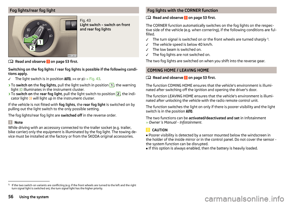
Fog lights/rear fog lightFig. 43
Light switch – switch on front
and rear fog lights
Read and observe on page 53 first.
Switching on the fog lights / rear fog lights is possible if the following condi-
tions apply.
The light switch is in position ,
or
» Fig. 43 .
›
To switch on the fog lights , pull the light switch in position
1
; the warning
light illuminates in the instrument cluster.
›
To
switch on the rear fog light , pull the light switch to position
2
, the indi-
cator light will light up in the instrument cluster.
If the vehicle is not fitted with fog lights, the rear fog light is switched on by
pulling out the light switch to the only possible setting.
The fog lights/rear fog light are switched off in the reverse order.
Note
While driving with an accessory connected to the trailer socket (e.g. trailer,
bike carrier) only the equipment is illuminated by the fog light. The towing de-
vice must be installed at the factory or from the ŠKODA original accessories.Fog lights with the CORNER function
Read and observe
on page 53 first.
The CORNER function automatically switches on the fog lights on the respec-tive side of the vehicle (e.g. when cornering), if the following conditions are ful-
filled.
The turn signal is switched on or the front wheels are turned sharply 1)
.
The vehicle speed is below 40 km/h.
The low beam is switched on.
The fog lights are not switched on.
The two fog lights are switched on when you shift into the reverse gear.
COMING HOME / LEAVING HOME
Read and observe
on page 53 first.
The function COMING HOME ensures that the vehicle's environment is illumi-
nated after switching off the ignition and opening the driver's door.
The function LEAVING HOME ensures that the vehicle's environment is illumi-
nated after unlocking the vehicle with the radio remote control unit.
The function switches the light on only if there is poorer visibility and the light
switch is in the position .
The two functions can be activated/deactivated and set in Infotainment
» Owner´s Manual - Infotainment .
CAUTION
■
Poorer visibility is detected by a sensor mounted below the windscreen in
the holder of the inside mirror or in the control panel. Do not cover the sensor -
the system function can be disrupted.■
If this option is always enabled, then the battery is heavily loaded.
1)
If the two switch-on variants are conflicting (e.g. if the front wheels are turned to the left and the right
turn signal light is switched on), the turn signal light has the higher priority.
56Using the system
Page 59 of 184
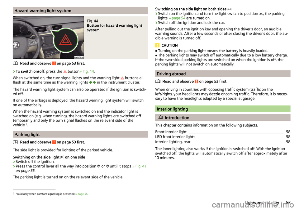
Hazard warning light systemFig. 44
Button for hazard warning light
system
Read and observe on page 53 first.
›
To switch on/off , press the
button
» Fig. 44 .
When switched on, the turn signal lights and the warning light buttons all
flash at the same time as the warning lights
in the instrument cluster.
The hazard warning light system can also be operated if the ignition is switch-
ed off.
If one of the airbags is deployed, the hazard warning light system will switch
on automatically.
When the hazard warning system is switched on and the indicator light is
switched on (e.g. when turning), the hazard warning lights are switched off
temporarily and only the turn signal flashes on the relevant side of the
vehicle 1)
.
Parking light
Read and observe
on page 53 first.
The side light is provided for lighting of the parked vehicle.
Switching on the side light on one side
›
Switch off the ignition.
›
Press the control lever all the way into position
or
until it stops
» Fig. 41
on page 55 .
The parking light is turned on on the relevant side of the vehicle.
Switching on the side light on both sides ›Switch on the ignition and turn the light switch to position , the parking
lights » page 54 are turned on.›
Switch off the ignition and lock the car.
After pulling out the ignition key and opening the driver's door, an audible
warning sounds. After a few seconds or after closing the driver's door, the au-
dible warning is turned off.
CAUTION
■ Turning on the parking light means the battery is heavily loaded.■The parking lights may switch off automatically due to a low battery charge.
If the two-sided parking lights are switched on when the ignition is off, the
parking lights will not switch on automatically.
Driving abroad
Read and observe
on page 53 first.
When driving in countries with opposing traffic system (traffic on the
left/right), your headlights may dazzle oncoming traffic. Therefore, it is neces-
sary to have the headlights adapted by a specialist garage.
Interior lighting
Introduction
This chapter contains information on the following subjects:
Front interior light
58
LED front interior lights
58
Interior lighting, rear
58
The inner lighting also works if the ignition is switched off. With the ignition
switched off, the lights will automatically switch off after approximately after
10 minutes.
1)
Valid only when comfort signalling is activated » page 55.
57Lights and visibility
Page 90 of 184
Note■The engine running noises may be louder at first for a short time after start-
ing the cold engine.■
You should not switch on any major electrical components during the heat-
ing period, otherwise the vehicle battery will be drained unnecessarily.
■
After switching off the ignition, the radiator fan may (also intermittently)
continue to operate for approx. 10 minutes.
Problems with the engine start - vehicles with starter button
Fig. 105
Starting the engine - Press the
button with the key
Read and observe and on page 86 first.
If no engine start is possible and the display of the instrument cluster shows a
message that the key could not be detected by the system or there is a system
fault, then try to start the engine as follows.
›
Press the starter button with the key » Fig. 105.
If the engine does not start, the help of a specialist garage is required.
CAUTION
The key may not be detected by the system if the battery in the key is running
out of charge or the signal fails (strong electromagnetic field) or is shielded
(e.g. in an aluminium case).
START-STOPsystem
Introduction
This chapter contains information on the following subjects:
Operation
88
Manually deactivating/activating the system
89The START STOPsystem (hereinafter referred to as the system) reduces
CO 2emissions and harmful emissions, and saves fuel.
If the system determine that the engine is not needed when the vehicle stops
(e.g. at the traffic lights), it turns off the engine and starts it again when mov-
ing off.
The system function depends on many factors. Some of them are down to the
driver, while others are systemic and can neither be influenced nor identified.
For this reason, the system may react differently in situations which seem
identical from the driver's perspective.
The system is automatically activated every time the ignition is switched on
(even when it has previously been manually deactivated with the button).
Note
If the engine has stopped due to the system, the ignition remains switched on.
Operation
Fig. 106
Display
Vehicles with manual transmission
The engine is automatically switched off as soon as the vehicle comes to a
halt, the shift lever is moved into neutral and the clutch pedal is released.
The engine is automatically started as soon as the clutch pedal is depressed.
Vehicles with automatic transmission
The engine is automatically switched off as soon as the vehicle comes to a
halt and the brake pedal is operated.
The engine is automatically started as soon as the brake pedal is released.
88Driving
Page 104 of 184
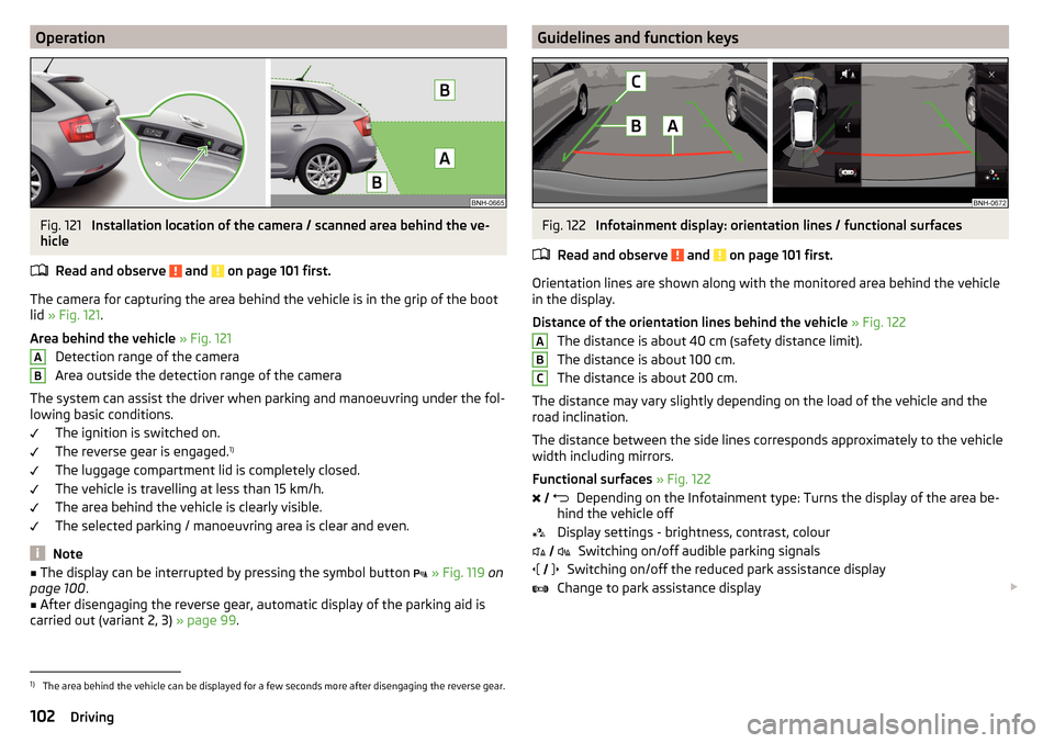
OperationFig. 121
Installation location of the camera / scanned area behind the ve-
hicle
Read and observe
and on page 101 first.
The camera for capturing the area behind the vehicle is in the grip of the bootlid » Fig. 121 .
Area behind the vehicle » Fig. 121
Detection range of the camera
Area outside the detection range of the camera
The system can assist the driver when parking and manoeuvring under the fol- lowing basic conditions.
The ignition is switched on.
The reverse gear is engaged. 1)
The luggage compartment lid is completely closed.
The vehicle is travelling at less than 15 km/h.
The area behind the vehicle is clearly visible.
The selected parking / manoeuvring area is clear and even.
Note
■ The display can be interrupted by pressing the symbol button » Fig. 119 on
page 100 .■
After disengaging the reverse gear, automatic display of the parking aid is
carried out (variant 2, 3) » page 99.
ABGuidelines and function keysFig. 122
Infotainment display: orientation lines / functional surfaces
Read and observe
and on page 101 first.
Orientation lines are shown along with the monitored area behind the vehicle
in the display.
Distance of the orientation lines behind the vehicle » Fig. 122
The distance is about 40 cm (safety distance limit).
The distance is about 100 cm.
The distance is about 200 cm.
The distance may vary slightly depending on the load of the vehicle and the
road inclination.
The distance between the side lines corresponds approximately to the vehicle
width including mirrors.
Functional surfaces » Fig. 122
Depending on the Infotainment type: Turns the display of the area be-
hind the vehicle off
Display settings - brightness, contrast, colour Switching on/off audible parking signals
Switching on/off the reduced park assistance display
Change to park assistance display
ABC
1)
The area behind the vehicle can be displayed for a few seconds more after disengaging the reverse gear.
102Driving
Page 112 of 184
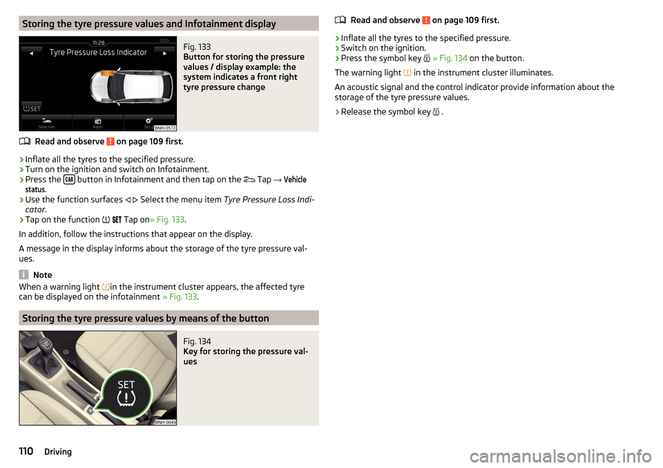
Storing the tyre pressure values and Infotainment displayFig. 133
Button for storing the pressure
values / display example: the
system indicates a front right
tyre pressure change
Read and observe on page 109 first.
›
Inflate all the tyres to the specified pressure.
›
Turn on the ignition and switch on Infotainment.
›
Press the button in Infotainment and then tap on the
Tap
→
Vehiclestatus
.
›
Use the function surfaces
Select the menu item
Tyre Pressure Loss Indi-
cator .
›
Tap on the function
Tap on
» Fig. 133 .
In addition, follow the instructions that appear on the display.
A message in the display informs about the storage of the tyre pressure val-
ues.
Note
When a warning light in the instrument cluster appears, the affected tyre
can be displayed on the infotainment » Fig. 133.
Storing the tyre pressure values by means of the button
Fig. 134
Key for storing the pressure val-
ues
Read and observe on page 109 first.›
Inflate all the tyres to the specified pressure.
›
Switch on the ignition.
›
Press the symbol key
» Fig. 134 on the button.
The warning light
in the instrument cluster illuminates.
An acoustic signal and the control indicator provide information about the
storage of the tyre pressure values.
›
Release the symbol key
.
110Driving
Page 151 of 184
›If it is not possible to start the engine, switch on the ignition so that the
steering wheel does not lock and so that the turn signal lights, windscreen
wipers and windscreen washer system can be used.›
Take the vehicle out of gear or move the selector lever into position N if the
vehicle is fitted with an automatic gearbox.
›
Keep the tow rope taut at all times during the towing procedure.
WARNING■ Spiral tow ropes must not be used for towing » Fig. 173- , the towing
eye may unscrew out of the vehicle - risk of accident.■
The tow rope should not be twisted - there is a risk of accidents.
CAUTION
■ Do not tow-start the engine – risk of damaging the engine! The battery from
another vehicle can be used as a jump-start aid » page 147, Jump-starting .■
For off-road towing manoeuvres, there is a risk to both vehicles that the fas-
teners may become overloaded and damaged.
Note
We recommend that you use a tow rope from ŠKODA Original Accessories.
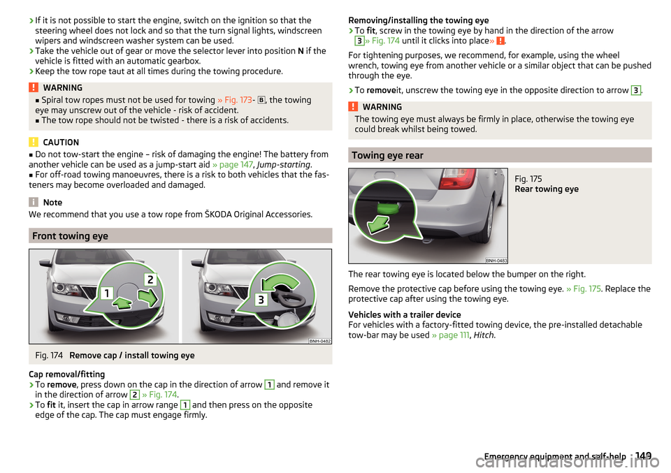
Front towing eye
Fig. 174
Remove cap / install towing eye
Cap removal/fitting
›
To remove , press down on the cap in the direction of arrow
1
and remove it
in the direction of arrow
2
» Fig. 174 .
›
To fit it, insert the cap in arrow range
1
and then press on the opposite
edge of the cap. The cap must engage firmly.
Removing/installing the towing eye›To fit, screw in the towing eye by hand in the direction of the arrow3
» Fig. 174 until it clicks into place » .
For tightening purposes, we recommend, for example, using the wheel
wrench, towing eye from another vehicle or a similar object that can be pushed through the eye.
›
To remove it, unscrew the towing eye in the opposite direction to arrow
3
.
WARNINGThe towing eye must always be firmly in place, otherwise the towing eye
could break whilst being towed.
Towing eye rear
Fig. 175
Rear towing eye
The rear towing eye is located below the bumper on the right.
Remove the protective cap before using the towing eye. » Fig. 175. Replace the
protective cap after using the towing eye.
Vehicles with a trailer device
For vehicles with a factory-fitted towing device, the pre-installed detachable
tow-bar may be used » page 111, Hitch .
149Emergency equipment and self-help
Page 158 of 184
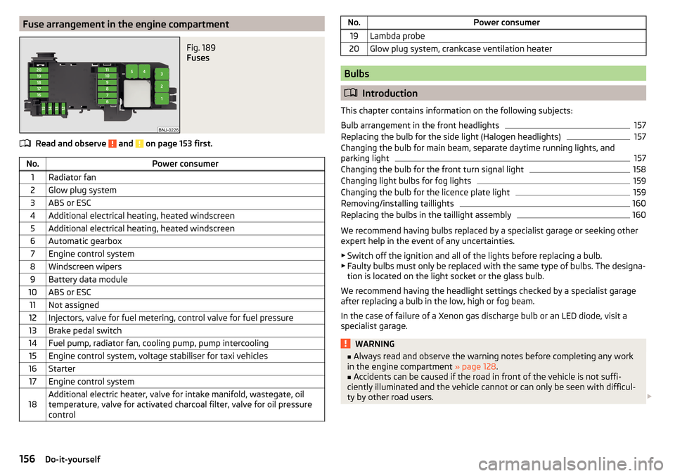
Fuse arrangement in the engine compartmentFig. 189
Fuses
Read and observe and on page 153 first.
No.Power consumer1Radiator fan2Glow plug system3ABS or ESC4Additional electrical heating, heated windscreen5Additional electrical heating, heated windscreen6Automatic gearbox7Engine control system8Windscreen wipers9Battery data module10ABS or ESC11Not assigned12Injectors, valve for fuel metering, control valve for fuel pressure13Brake pedal switch14Fuel pump, radiator fan, cooling pump, pump intercooling15Engine control system, voltage stabiliser for taxi vehicles16Starter17Engine control system18Additional electric heater, valve for intake manifold, wastegate, oil
temperature, valve for activated charcoal filter, valve for oil pressure
controlNo.Power consumer19Lambda probe20Glow plug system, crankcase ventilation heater
Bulbs
Introduction
This chapter contains information on the following subjects:
Bulb arrangement in the front headlights
157
Replacing the bulb for the side light (Halogen headlights)
157
Changing the bulb for main beam, separate daytime running lights, and
parking light
157
Changing the bulb for the front turn signal light
158
Changing light bulbs for fog lights
159
Changing the bulb for the licence plate light
159
Removing/installing taillights
160
Replacing the bulbs in the taillight assembly
160
We recommend having bulbs replaced by a specialist garage or seeking other
expert help in the event of any uncertainties.
▶ Switch off the ignition and all of the lights before replacing a bulb.
▶ Faulty bulbs must only be replaced with the same type of bulbs. The designa-
tion is located on the light socket or the glass bulb.
We recommend having the headlight settings checked by a specialist garage after replacing a bulb in the low, high or fog beam.
In the case of failure of a Xenon gas discharge bulb or an LED diode, visit a
specialist garage.
WARNING■ Always read and observe the warning notes before completing any work
in the engine compartment » page 128.■
Accidents can be caused if the road in front of the vehicle is not suffi-
ciently illuminated and the vehicle cannot or can only be seen with difficul-
ty by other road users.
156Do-it-yourself
Page 159 of 184
WARNING (Continued)■H7 and H15 bulbs are pressurised and may burst when changing the bulb -
risk of injury! We therefore recommended wearing gloves and safety
glasses when changing a bulb.■
Do not carry out any work on the Xenon gas discharge lamps - risk of
death!
CAUTION
■ Do not take hold of the glass bulb with naked fingers (even the smallest
amount of dirt reduces the working life of the light bulb). Use a clean cloth,
napkin, or similar.■
The cap of the filament bulb must always be seated correctly in the head-
light, otherwise this may allow water and debris to enter the headlight - risk of
damage to the headlights.
Note
■ This Owner's Manual only describes the replacement of bulbs where it is pos-
sible to replace the bulbs on your own without any complications arising. Other
bulbs must be replaced by a specialist garage.■
We recommend that a box of replacement bulbs always be carried in the ve-
hicle.
Bulb arrangement in the front headlights
Fig. 190
Left headlight
Read and observe and on page 156 first.
Bulb arrangement » Fig. 190
Low beam or low beam with Xenon gas discharge lamp
Main beam, separate daytime running lights, and parking light
Turn signal light (at the front)
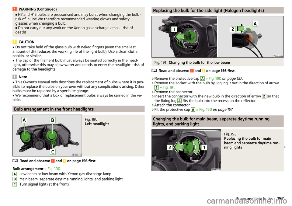
ABCReplacing the bulb for the side light (Halogen headlights)Fig. 191
Changing the bulb for the low beam
Read and observe
and on page 156 first.
›
Remove the protective cap
A
» Fig. 190 on page 157 .
›
Remove the socket with the bulb by jiggling it out in the direction of arrow
1
» Fig. 191 .
›
Remove the connector.
›
Insert the connector with the new bulb in the direction of arrow
2
so that
the fixing lug
A
fits the bulb into the recess on the reflector.
›
Attach the connector.
›
Fit the protective cap
A
» Fig. 190 on page 157 .
Changing the bulb for main beam, separate daytime running
lights, and parking light
Fig. 192
Replacing the bulb for main
beam and separate daytime run-
ning lights
157Fuses and light bulbs
Page 160 of 184
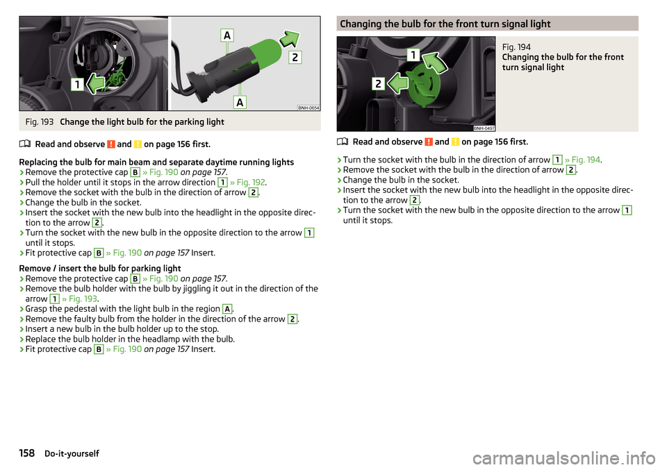
Fig. 193
Change the light bulb for the parking light
Read and observe
and on page 156 first.
Replacing the bulb for main beam and separate daytime running lights
›
Remove the protective cap
B
» Fig. 190 on page 157 .
›
Pull the holder until it stops in the arrow direction
1
» Fig. 192 .
›
Remove the socket with the bulb in the direction of arrow
2
.
›
Change the bulb in the socket.
›
Insert the socket with the new bulb into the headlight in the opposite direc-
tion to the arrow
2
.
›
Turn the socket with the new bulb in the opposite direction to the arrow
1
until it stops.
›
Fit protective cap
B
» Fig. 190 on page 157 Insert.
Remove / insert the bulb for parking light
›
Remove the protective cap
B
» Fig. 190 on page 157 .
›
Remove the bulb holder with the bulb by jiggling it out in the direction of the
arrow
1
» Fig. 193 .
›
Grasp the pedestal with the light bulb in the region
A
.
›
Remove the faulty bulb from the holder in the direction of the arrow
2
.
›
Insert a new bulb in the bulb holder up to the stop.
›
Replace the bulb holder in the headlamp with the bulb.
›
Fit protective cap
B
» Fig. 190 on page 157 Insert.
Changing the bulb for the front turn signal lightFig. 194
Changing the bulb for the front
turn signal light
Read and observe and on page 156 first.
›
Turn the socket with the bulb in the direction of arrow
1
» Fig. 194 .
›
Remove the socket with the bulb in the direction of arrow
2
.
›
Change the bulb in the socket.
›
Insert the socket with the new bulb into the headlight in the opposite direc-
tion to the arrow
2
.
›
Turn the socket with the new bulb in the opposite direction to the arrow
1
until it stops.
158Do-it-yourself