battery SKODA RAPID SPACEBACK 2016 1.G Owner's Guide
[x] Cancel search | Manufacturer: SKODA, Model Year: 2016, Model line: RAPID SPACEBACK, Model: SKODA RAPID SPACEBACK 2016 1.GPages: 184, PDF Size: 28.1 MB
Page 118 of 184
Exterior mirrors
You should have additional exterior mirrors fitted if you are not able to see the
traffic behind the trailer using the standard rear-view mirrors.
Headlights
The front of the vehicle may lift up when a trailer (accessory) is being towed
and the headlights may dazzle other road users. Set the range of the head-
lights » page 54 .
Power supply of the trailer / accessory power system
In the electrical connection between the vehicle and trailer (accessory), the
trailer (accessories) is supplied with power from the vehicle (with ignition
switched on and off).
With the engine switched off, the vehicle battery is discharged by the connec-
ted consumers.
At low charge state of the vehicle battery, the power supply to the trailer (ac-
cessories) is interrupted.WARNING■ An improperly connected electrical installation of the trailer (accessories)
may result in an accident or serious injury from electrical shock.■
Do not make any adjustments to the electrical installation of the vehicle
and the trailer (accessories) - risk of an accident or serious injury from elec-
trical shock.
WARNING (Continued)■ After the electrical connection between the vehicle and trailer (accessory)
the trailer / accessory lights should be checked for function.■
Never use the securing eye to tow - risk of accident!
CAUTION
■ An improperly connected electrical installation of the trailer (accessories) can
lead to the inoperability of the vehicle electronics.■
The total power consumption of all the connected consumers to the trailer
power supply must not exceed 350 watts, otherwise there is a risk of damage
to the electrical system of the vehicle.
Loading a trailer
Correct the tyre inflation pressure on the vehicle for “full load” » page 137.
Distribution of the cargo
Distribute the cargo in the trailer in such a way that heavy items are located as
close to the trailer axle as possible. Secure the load from slipping.
The distribution of the weight is very poor if your vehicle is unladen and the
trailer is laden. Nevertheless, maintain a particularly low speed if you cannot
avoid driving with this combination.
WARNINGA sliding cargo can significantly adversely affect stability and driving safety
- there is a risk of accident!
Trailer load
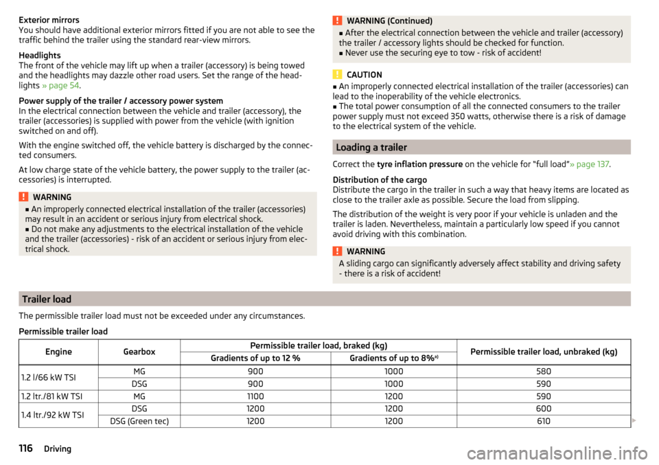
The permissible trailer load must not be exceeded under any circumstances.Permissible trailer loadEngineGearboxPermissible trailer load, braked (kg)Permissible trailer load, unbraked (kg)Gradients of up to 12 %Gradients of up to 8% a)1.2 l/66 kW TSIMG9001000580DSG90010005901.2 ltr./81 kW TSIMG110012005901.4 ltr./92 kW TSIDSG12001200600DSG (Green tec)12001200610
116Driving
Page 120 of 184
General Maintenance
Care and maintenance
Service work, adjustments and technical alterations
Introduction
This chapter contains information on the following subjects:
Vehicle operating under different weather conditions
118
Statutory checks
118
ŠKODA service partner
118
ŠKODA Original parts
119
ŠKODA Original accessories
119
Spoiler
119
Component protection
119
Airbags
119
Acceptance and recycling of used vehicles
120
The instructions and guidelines from ŠKODA AUTO must be observed when us-
ing accessories or carrying out any modifications, repairs or technical altera-
tions to your vehicle.
Adhering to these instructions and guidelines helps ensure road safety and
helps keep your vehicle in a good technical condition.
WARNING■ Adjustments, repairs and technical changes to the vehicle should only be
carried out by a specialist. Work carried out incorrectly (including work on
the electronic components and their software) can result in malfunctions -
there is a risk of accident and, potentially, increased wear on parts!■
We recommend that you use only ŠKODA Original Accessories and ŠKODA
Original Parts which have been expressly approved for use on your vehicle.
Reliability, safety and suitability for your vehicle are guaranteed with these.
■
Do not use any products which have not been approved by ŠKODA AUTO,
even though these may be products with a type approval or which have
been approved by a nationally recognised testing laboratory.
Vehicle operating under different weather conditions
Read and observe
on page 118 first.
If you would like to operate your vehicle in countries other than those with its
intended weather conditions, you should contact a ŠKODA Partner. He or she
will advise you if certain precautions need to be taken to ensure the full func-
tioning of the vehicle or to prevent damage (e.g. coolant, changing the battery
or similar).
Statutory checks
Read and observe
on page 118 first.
Many countries have legislation requiring the operational reliability, safety and,
where applicable, roadworthiness and/or exhaust gas properties of a vehicle
to be tested at regular intervals. These tests can be carried out by workshops
or testing stations that have been legally authorised for this purpose.
The ŠKODA Service partners can prepare your vehicle for the official inspec-
tions, so as to ensure that it passes.
Even if you want to take your vehicle to an officially approved test centre for
prior checking in preparation for a legally required test, we recommend that
you consult your ŠKODA Service Partner beforehand.
ŠKODA service partner
Read and observe
on page 118 first.
All ŠKODA service partners work according to the instructions and guidelines
from ŠKODA AUTO. All service and repair work is therefore carried out on time
and to the appropriate quality. Adhering to these guidelines and instructions
helps ensure road safety and helps keep your vehicle in a good technical con-
dition.
We therefore advise you to have all modifications, repairs and technical altera-
tions to your vehicle carried out by a ŠKODA Service Partner.
118General Maintenance
Page 130 of 184
CAUTIONThe following instructions must be observed, otherwise there is a risk of dam-
age to the engine and to the exhaust system.■
If a different fuel other than diesel fuel, which complies to the above men-
tioned standards (e.g. petrol) is used, do not start the engine or switch on the
ignition!
■
The biofuel RME must not be used!
CAUTION
Diesel fuel additives■The diesel fuel in accordance with the prescribed standards meets all the
conditions for a smooth running engine. Therefore, we recommend that you do
not add any fuel additives to the diesel - there is a risk of engine damage or
damage to the exhaust system.
Engine compartment
Introduction
This chapter contains information on the following subjects:
Opening and closing the bonnet
129
Engine compartment overview
129
Windscreen washer fluid
130WARNINGNever cover the engine with additional insulation material (e.g. with a cov-
er) – risk of fire!WARNINGWhen working in the engine compartment, the following instructions must
be observed - otherwise risk of injury or fire. The engine compartment of
your car is a hazardous area!WARNINGInstructions before beginning work in the engine compartment■Stop the engine and remove the ignition key, on vehicles with the KESSY
system, open the driver's door.■
Firmly apply the handbrake.
WARNING (Continued)■ For vehicles with manual transmission the lever into the neutral position.
For vehicles with automatic transmission , place the selector lever in the P
position.■
Allow the engine to cool.
■
Never open the bonnet if you can see steam or coolant flowing out of the
engine compartment – risk of scalding! Wait until the steam or coolant has
stopped escaping.
WARNINGInformation for working in the engine compartment■Keep everyone away from the engine compartment.■
Do not touch any hot engine parts – risk of burns!
■
Never touch the radiator fan. The radiator fan may still turn suddenly
about 10 minutes after switching off the ignition!
■
Do not smoke in the vicinity of the engine and avoid the use of open
flames or sparks.
■
Do not leave any items (e.g. cloths or tools) in the engine compartment.
This presents a fire hazard and the risk of engine damage.
■
Read and observe the information and warning instructions on the fluid
containers.
WARNINGInformation for working in the engine compartment with the engine run-
ning■
If it is necessary to work on the engine with the engine running, beware
of rotating engine parts and electrical plants - they can be fatal!
■
Never touch the electric wiring on the ignition system.
■
Avoid short circuits in the electrical system, particularly on the vehicle's
battery.
CAUTION
Only refill using fluids with the proper specification - risk of damage to the ve-
hicle!
Note
■ Fluids with the proper specifications can be purchased from the ŠKODA Origi-
nal Accessories or from the ŠKODA Genuine Parts ranges.■
We recommend you have the operating fluids replaced by a specialist garage.
128General Maintenance
Page 131 of 184
Opening and closing the bonnetFig. 151
Opening the bonnet
Read and observe
and on page 128 first.
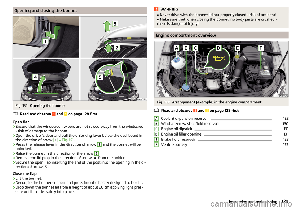
Open flap
›
Ensure that the windscreen wipers are not raised away from the windscreen
- risk of damage to the bonnet.
›
Open the driver's door and pull the unlocking lever below the dashboard in
the direction of arrow
1
» Fig. 151 .
›
Press the release lever in the direction of arrow
2
and the bonnet will be
unlocked.
›
Raise the bonnet in the direction of the arrow
3
.
›
Remove the lid prop in the direction of arrow
4
from the holder.
›
Secure the open flap inserting the end of the post into the opening in the di-
rection of arrow
5
.
Close the flap
›
Lift the bonnet.
›
Decouple the bonnet support and press into the holder designed to hold it.
›
Drop down the bonnet lid from a height of about 20 cm applying light pres-
sure until it clicks safely into place.
WARNING■ Never drive with the bonnet lid not properly closed - risk of accident!■Make sure that when closing the bonnet, no body parts are crushed -
there is danger of injury!
Engine compartment overview
Fig. 152
Arrangement (example) in the engine compartment
Read and observe
and on page 128 first.
Coolant expansion reservoir
132
Windscreen washer fluid reservoir
130
Engine oil dipstick
131
Engine oil filler opening
131
Brake fluid reservoir
133
Vehicle battery
133ABCDEF129Inspecting and replenishing
Page 135 of 184

Brake fluidFig. 156
Brake fluid reservoir
Check the brake fluid under the following conditions.The vehicle is on a horizontal surface.
The engine is turned off.
Check brake fluid level - the brake fluid level must lie between the markings
“MIN” and “MAX” » Fig. 156.
Specification - the brake fluid must comply with the standard VW 501 14 (this
standard meets the requirements of FMVSS 116 DOT4).
WARNING■ The following instructions must be followed at all times when working on
the engine compartment » page 128.■
If the fluid level drops significantly within a short time or if it drops below
the “MIN” » Fig. 156mark, this may be an indication of a leak in the brake
system.
Stop driving - There is a risk of an accident! Seek help from a
specialist garage.
Note
■ The brake fluid is changed as part of a compulsory inspection service.■Too low brake fluid level is indicated by the warning light being shown on
the display of the instrument cluster as well as the corresponding message
» page 30 . We still recommend inspecting the brake fluid level in the reservoir
from time to time.Vehicle battery
Introduction
This chapter contains information on the following subjects:
Check condition
134
Charging
135
Disconnect/reconnect and change
135
The vehicle battery represents a power source for the motor to start and for the supply of electrical consumers in the car.
Depending on the engine, the vehicle battery is either in the engine compart-
ment or the luggage compartment.
Automatic shutdown of consumers - vehicle battery discharge protection
The on-board power supply system tries to prevent the vehicle battery from
discharging in the following ways when it is subject to heavy loading. ▶ By increasing the engine idle speed.
▶ Through the power limitation of certain consumers.
▶ By switching off some consumers (e.g. heated seats) for as long as necessa-
ry.
Warning symbols on the vehicle battery
SymbolMeaningAlways wear eye protection!Battery acid is severely caustic. Always wear gloves and eye pro-
tection!Keep fire, sparks, open flames and lit cigarettes well clear of the
vehicle battery!When charging the vehicle battery, a highly explosive gas mixture
is produced!Keep children away from the vehicle battery! 133Inspecting and replenishing
Page 136 of 184
WARNINGBattery acid is highly corrosive - it can cause injury, chemical burns or poi-
soning! Corrosive vapours in the air irritate and damage the respiratory
tract and the eyes. The following guidelines must be observed.■
Always wear protective gloves, eye and skin protection when handling
the vehicle battery.
■
If your eyes or skin come into contact with the electrolytic fluid, immedi-
ately wash the affected area for a few minutes long with a lot of water.
Seek medical assistance without delay.
■
Keep the vehicle battery away from people who are not completely inde-
pendent (e.g. children).
■
Do not tilt the battery otherwise battery electrolyte may flow out of the
battery vent openings.
WARNINGWorking on the car battery may cause explosion, fire, injury or chemical
burn! The following guidelines must be observed.■
Do not smoke, use open flames or light or transmitting devices.
■
A discharged vehicle battery may freeze slightly. Never charge up a fro-
zen or thawed vehicle battery. Replace a frozen vehicle battery.
■
Never use a damaged vehicle battery.
■
Do not connect the battery terminals, bridging the two poles will cause a
short circuit.
CAUTION
Ensure that battery acid does not come into contact with the bodywork – risk
of damage to the paintwork.
Note
■ We recommend having all work on the vehicle battery carried out by a spe-
cialist garage.■
You should replace batteries older than 5 years.
Check conditionFig. 157
Vehicle battery: Open the cover / acid level indicator
Read and observe
and on page 134 first.
The battery condition is checked regularly by a specialist garage as part of the inspection service.
Check the acid level
For car batteries with acid level indicator, acidity can be checked on the basis
of a colour display. In vehicle batteries with the label “AGM” there is no acid
level examination.
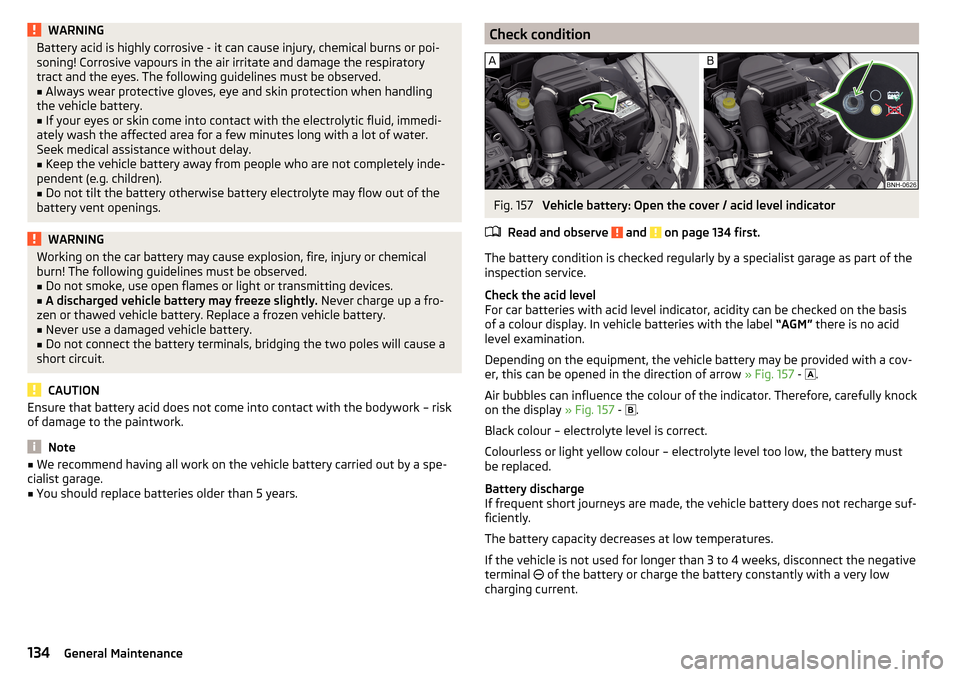
Depending on the equipment, the vehicle battery may be provided with a cov-
er, this can be opened in the direction of arrow » Fig. 157 -
.
Air bubbles can influence the colour of the indicator. Therefore, carefully knock
on the display » Fig. 157 -
.
Black colour – electrolyte level is correct.
Colourless or light yellow colour – electrolyte level too low, the battery must
be replaced.
Battery discharge
If frequent short journeys are made, the vehicle battery does not recharge suf-
ficiently.
The battery capacity decreases at low temperatures.
If the vehicle is not used for longer than 3 to 4 weeks, disconnect the negative
terminal of the battery or charge the battery constantly with a very low
charging current.
134General Maintenance
Page 137 of 184
ChargingRead and observe
and on page 134 first.
Only charge the battery when the ignition and all consumers are switched off.Refer to the instructions of the charger manufacturer.
Charging
›
For vehicles withthe START-STOPsystem or auxiliary heater, connect the
terminal of the charger on the battery’s
pole, the
terminal of the charg-
er to the earth point of the engine » page 147.
›
For vehicles without the START-STOPsystem or auxiliary heating, connect
the charger terminals to the corresponding battery poles ( to
,
to
).
›
Plug the mains cable of the charger into the power socket and switch on the
device.
›
After charging has been successful: Switch off the charger and remove the
mains cable from the power socket.
›
Disconnect the terminals of the charger from the vehicle battery.
A charging current of 0.1 multiple of the total vehicle battery capacity (or low-
er) must be used until full charging is achieved.
WARNING■ When charging the vehicle battery, hydrogen is released - risk of explo-
sion. An explosion can be caused through sparking while unclamping or
loosening the cable plug.■
So-called“quick-charging” of the vehicle battery is dangerous and re-
quires a special charger and specialist knowledge. Therefore, have“Quick
loading” carried out by a specialist garage.
Disconnect/reconnect and change
Read and observe
and on page 134 first.
The new vehicle battery must have the same capacity, voltage, current and
size as the original battery.
We recommend you have the battery replaced by a specialist garage.
›
To disconnect , switch off the ignition and disconnect the negative terminal
first , then disconnect the positive terminal
.
›
When
reconnecting the battery, reconnect the positive terminal
first, then
connect the negative terminal .
After disconnecting and re-connecting the vehicle battery, the following func-
tions or devices are partially or completely inoperative.Function / deviceCommissioningWindows» page 53Time settings» page 38
CAUTION
■ Disconnect the battery only with the ignition and consumers turned off - risk
of damaging the electrical system of the vehicle.■
Before disconnecting the battery, close all the electric windows - otherwise
malfunctions of the window can occur.
■
Under no circumstances mix up the charging cables – risk of fire.
Note
After disconnecting and reconnecting the vehicle battery, we recommend hav-
ing the vehicle checked by a specialist to ensure that the full functionality of
the vehicle is guaranteed.135Inspecting and replenishing
Page 142 of 184

Do-it-yourself
Emergency equipment and self-help
Emergency equipment
Introduction
This chapter contains information on the following subjects:
Placement of the first aid kit and warning triangle
140
Location of reflective vest
140
fire extinguisher
140
Vehicle tool kit
141
Placement of the first aid kit and warning triangle
Fig. 160
Placing of the first-aid kit and the warning triangle
The following information is for the first aid kit and warning triangle from the
ŠKODA Original accessories valid.
Placing the first-aid kit
The first-aid box can be attached by a strap to the right-hand side of the boot
» Fig. 160 .
Placing of the warning triangle - variant 1
The warning triangle can be inserted into the recess under the loading edge
and secured with the fastener tape » Fig. 160 -
.
Placing of the warning triangle - variant 2
On vehicles with the vehicle battery in the boot warning triangle can be stow-
ed in a box under the floor covering in the luggage compartment » Fig. 160 -
.
WARNINGProperly secure the first aid kit and the warning triangle - there is a risk of
injury in the event of sudden braking or a vehicle collision.
Location of reflective vest
Fig. 161
Storage compartment for the re-
flective vest
The reflective vest can be stored in a bracket under the driver's seat » Fig. 161.
fire extinguisher
Fig. 162
Release the fire extinguisher
The fire extinguisher is attached by two straps in a holder underneath the driv-
er's seat.
›
To remove the fire extinguisher, release the safety catches on the two belts
in the direction of arrow » Fig. 162 and remove the fire extinguisher.
›
To secure , place the fire extinguisher back in the mount and secure with the
belts.
The Owner´s Manual is fitted next to the fire extinguisher.
Pay attention to the expiration date of the fire extinguisher. After this date,
the correct function of the device is not guaranteed.
140Do-it-yourself
Page 144 of 184

›Jack up the vehicle
» page 144 until the wheel that needs changing is clear of
the ground.›
Unscrew the wheel bolts and place them on a clean surface (cloth, paper,
etc.).
›
Remove the wheel carefully.
›
Attach the spare wheel and slightly screw on the wheel bolts.
›
Lower the vehicle.
›
Tighten the wheel bolts opposite each other using the wheel wrench (“pull- ing crossways”) » page 144.
›
Replace the wheel trim » page 143 and caps » page 143 .
When fitting unidirectional tyres, ensure that the direction of rotation is cor-
rect » page 136 .
All bolts must be clean and must turn easily. If screws are corroded and diffi-
cult to move, these must be replaced.
WARNING■ Undo the wheel bolts just a little (about one turn), provided the vehicle
has not yet been jacked up. Otherwise the wheel could come loose and fall
off – risk of injury.■
Under no circumstances must the bolts be greased or oiled - cause an ac-
cident.
Subsequent steps
After changing the wheel, the following work must be carried out.
›
Stow the replaced wheel in the well under the floor covering of the luggage
compartment and secure it with a nut.
›
Stow the tool kit in the space provided and secure using the band.
›
Check tyre pressure on the mounted wheel and adjust if necessary and, with
vehicles with tyre pressure monitoring, save the tyre pressure values in the
system » page 109 .
›
Have the tightening torque of the wheel bolts checked as soon as possible.
The prescribed tightening torque is 120 Nm.
Replace the damaged wheel or consult a specialist garage about repair op-
tions.
WARNINGTightening torque which is too high can damage the threads and this can
result in permanent deformation of the contact surfaces on the rim. Where
tightening torque is too low, the wheels may become loose while driving -
risk of accident. Therefore drive cautiously and only at a moderate speed
until the tightening torque has been checked.
Removing/stowing the emergency or spare wheel
Fig. 164
Take out the wheel
The wheel is located in a well under the floor covering in the luggage compart-
ment and is fixed in place with a screw.
Take out the wheel
›
Lift up the floor in the luggage compartment.
›
Loosen the retaining belt and take out the box with the tool kit.
›
Unscrew the nut in the direction of arrow » Fig. 164 and take out the wheel.
Stow the wheel
›
Place the wheel into the wheel well with the wheel rim pointing downward.
On vehicles with the vehicle battery in the boot, lay down the wheel with the
outer face upward.
›
Pull the fixing band through the opposite holes in the wheel rim.
›
Screw the nut in the opposite direction to the arrow until it stops » Fig. 164.
›
Place the box with the tool kit back inside the wheel and secure it with the
tape.
›
Fold back the floor in the luggage compartment.
142Do-it-yourself
Page 149 of 184
If the tyre pressure is 1.3 bar or more›Set the tyre pressure back to the correct value » page 137.›
Continue driving carefully to the nearest specialist garage at a maximum
speed of 80 km/h (50 mph).
WARNINGA tyre filled with sealant has the same driving characteristics as a standard
tyre. The following guidelines must be observed.■
Do not drive faster than 80 km/h (50 mph).
■
Avoid accelerating at full throttle, sharp braking and fast cornering.
Jump-starting
Introduction
This chapter contains information on the following subjects:
Jump-starting using the battery from another vehicle
147WARNING■ The following instructions must be followed at all times when working on
the engine compartment » page 128.■
When handling the vehicle battery, the following warnings must be ob-
served » page 133 .
■
A discharged vehicle battery may already freeze at temperatures just be-
low 0 °C. If the battery is frozen, do not carry out a jump start with the bat-
tery of another vehicle – risk of explosion and injury!
■
Never jump-start vehicle batteries with an electrolyte level that is too low
– risk of explosion and caustic burns.
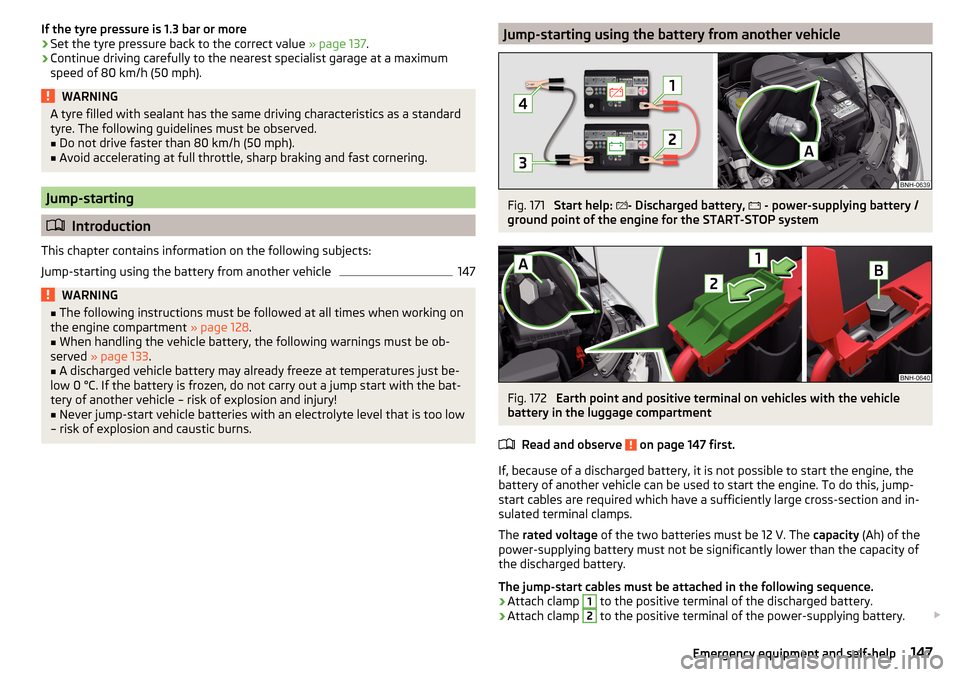
Jump-starting using the battery from another vehicleFig. 171
Start help:
- Discharged battery,
- power-supplying battery /
ground point of the engine for the START-STOP system
Fig. 172
Earth point and positive terminal on vehicles with the vehicle
battery in the luggage compartment
Read and observe
on page 147 first.
If, because of a discharged battery, it is not possible to start the engine, the
battery of another vehicle can be used to start the engine. To do this, jump-
start cables are required which have a sufficiently large cross-section and in-
sulated terminal clamps.
The rated voltage of the two batteries must be 12 V. The capacity (Ah) of the
power-supplying battery must not be significantly lower than the capacity of
the discharged battery.
The jump-start cables must be attached in the following sequence.
›
Attach clamp
1
to the positive terminal of the discharged battery.
›
Attach clamp
2
to the positive terminal of the power-supplying battery.
147Emergency equipment and self-help