belt SKODA RAPID SPACEBACK 2016 1.G Owner's Guide
[x] Cancel search | Manufacturer: SKODA, Model Year: 2016, Model line: RAPID SPACEBACK, Model: SKODA RAPID SPACEBACK 2016 1.GPages: 184, PDF Size: 28.1 MB
Page 66 of 184
Setting the armrest heightFig. 55
Raise armrest
Read and observe on page 63 first.
›
To adjust the height , lift the armrest in the direction of the arrow into one of
the six locking positions » Fig. 55.
›
To fold down , lift the armrest in the direction of the arrow up to the stop and
then fold back down again.
Rear seats
Introduction
This chapter contains information on the following subjects:
Seat backrests
64
Fold down armrest
65
Seat backrests
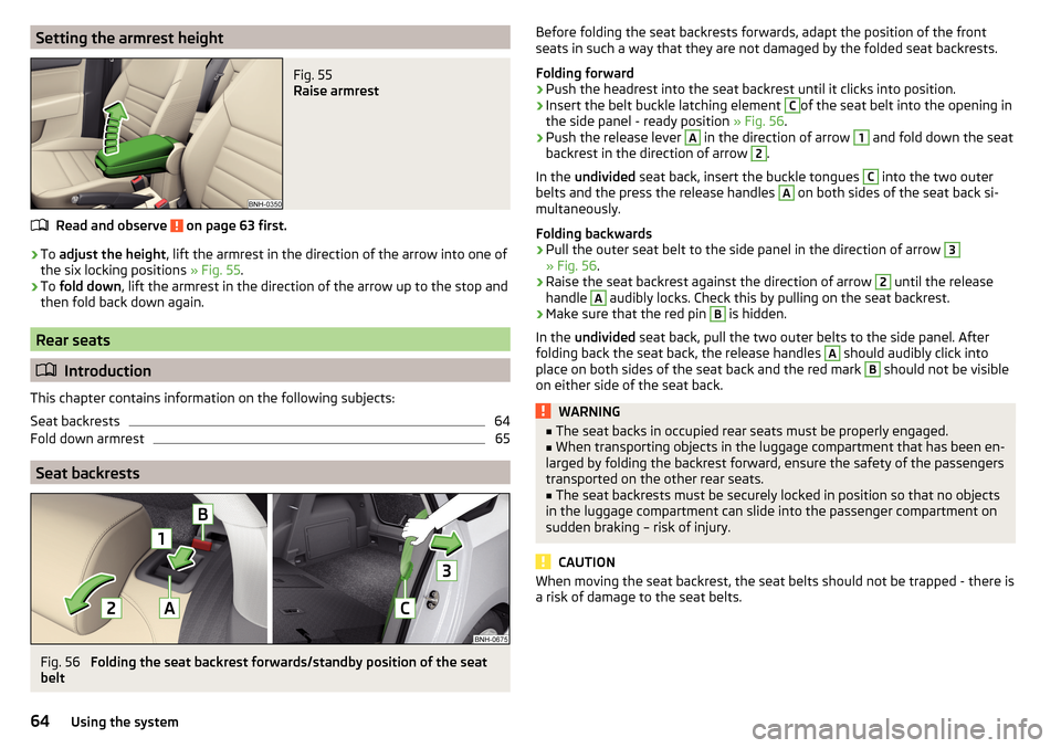
Fig. 56
Folding the seat backrest forwards/standby position of the seat
belt
Before folding the seat backrests forwards, adapt the position of the front
seats in such a way that they are not damaged by the folded seat backrests.
Folding forward›
Push the headrest into the seat backrest until it clicks into position.
›
Insert the belt buckle latching element
C
of the seat belt into the opening in
the side panel - ready position » Fig. 56.
›
Push the release lever
A
in the direction of arrow
1
and fold down the seat
backrest in the direction of arrow
2
.
In the undivided seat back, insert the buckle tongues
C
into the two outer
belts and the press the release handles
A
on both sides of the seat back si-
multaneously.
Folding backwards
›
Pull the outer seat belt to the side panel in the direction of arrow
3
» Fig. 56 .
›
Raise the seat backrest against the direction of arrow
2
until the release
handle
A
audibly locks. Check this by pulling on the seat backrest.
›
Make sure that the red pin
B
is hidden.
In the undivided seat back, pull the two outer belts to the side panel. After
folding back the seat back, the release handles
A
should audibly click into
place on both sides of the seat back and the red mark
B
should not be visible
on either side of the seat back.
WARNING■ The seat backs in occupied rear seats must be properly engaged.■When transporting objects in the luggage compartment that has been en-
larged by folding the backrest forward, ensure the safety of the passengers
transported on the other rear seats.■
The seat backrests must be securely locked in position so that no objects
in the luggage compartment can slide into the passenger compartment on
sudden braking – risk of injury.
CAUTION
When moving the seat backrest, the seat belts should not be trapped - there is
a risk of damage to the seat belts.64Using the system
Page 91 of 184
Requirements for the system to function correctly
The following conditions must be met for the system to function correctly.
The driver's door is closed.
The driver has fastened the seat belt.
The driving speed was higher than 4 km/h after the last stop.
No trailer or other accessory is connected to the trailer socket.
System status
The system status is shown in the display when the vehicle comes to a halt
» Fig. 106 .
The engine is switched off automatically; when moving off, the ignition
process will be initiated automatically.
The engine is not switched off automatically.
The engine does not shut down when the vehicle stops, if e.g. the following
applies.
▶ The engine temperature for the proper function of the system has not yet
been reached.
▶ The charge state of the vehicle battery is too low.
▶ The current consumption is too high.
▶ High air conditioning or heating output (high fan speed, big difference be-
tween the desired and actual interior temperature).
If the engine has shut down automatically but the system detects that the en- gine is required to run (e.g. if the brake pedal is pressed repeatedly) then the
system automatically starts up the engine.
More information about the current system status can be displayed on the In-
fotainment screen » Owner´s Manual - Infotainment .
If there is a system fault , the following message will appear in the display of
the instrument cluster. Seek help from a specialist garage.Note■ If the driver's seat belt is removed for more than 30 seconds or the driver's
door is opened after the engine has switched off automatically, the engine will
have to be restarted manually.■
No automatic engine shut-down takes place when a vehicle with automatic
transmission is moving at low speed (e.g. during a traffic jam) and remains sta-
tionary after pressing the brake pedal lightly. Automatic engine shut-down
takes place if you press the brake pedal down with more force.
■
For vehicles with automatic transmission there is no automatic engine shut-
down when the system detects a manoeuvring action due to a large steering
angle.
Manually deactivating/activating the system
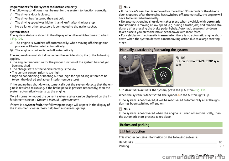
Fig. 107
Button for the START-STOP sys-
tem
›
To deactivate/activate the system, press the
button » Fig. 107 .
When the system is deactivated, the symbol
in the button lights up.
If the system is deactivated, it will be reactivated automatically after the igni-
tion has been switched off and on.
Note
If the system is deactivated when the engine is turned off automatically, then
the automatic start process takes place.
Brakes and parking
Introduction
This chapter contains information on the following subjects:
Handbrake
90
Parking
91
89Starting-off and Driving
Page 110 of 184
Deactivation/activationFig. 132
Keys / dial: on the operating lever / the multifunction steering
wheel
Read and observe
and on page 106 first.
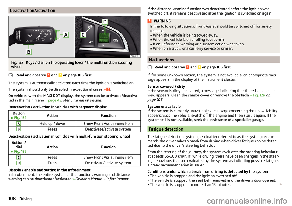
The system is automatically activated each time the ignition is switched on.The system should only be disabled in exceptional cases »
.
On vehicles with the MAXI DOT display, the system can be activated/deactiva- ted in the main menu » page 42, Menu item
Assist systems
.
Deactivation / activation in vehicles with segment display
Button
» Fig. 132ActionFunctionAHold up / downShow Front Assist menu itemBPressDeactivate/activate system
Deactivation / activation in vehicles with multi-function steering wheel
Button / dial
» Fig. 132ActionFunction
CPressShow Front Assist menu itemDPressDeactivate/activate system
Disable / enable and setting in the Infotainment
In Infotainment, the entire system or the functions warning and distance
warning can be deactivated/activated » Owner´s Manual - Infotainment .
If the distance-warning function was deactivated before the ignition was
switched off, it remains deactivated after the ignition is switched on again.WARNINGIn the following situations, Front Assist should be switched off for safety
reasons.■
When the vehicle is being towed away.
■
When the vehicle is on a rolling test bench.
■
If an unfounded warning or a system action was taken.
■
When on a truck, or a car ferry service or similar.
Malfunctions
Read and observe
and on page 106 first.
If, for some unknown reason, the system is not available, an appropriate mes-
sage appears in the display of the instrument cluster.
Sensor covered / dirty
If the sensor is dirty or covered, a message indicating that there is no sensor
view appears. Clean the sensor cover or remove the obstacle » Fig. 129 on
page 106 .
System unavailable
If the system is currently unavailable, a message concerning the unavailability
appears. Stop the vehicle, switch off the engine and then start it again. If the
system still is not available, seek the assistance of a specialist garage.
Fatigue detection
The fatigue detection system (hereinafter referred to as the system) recom-
mends the driver takes a break from driving when driver fatigue can be detec-
ted due to the driver's steering behaviour.
From the starting of the journey, the system evaluates the steering behaviour
at speeds 65-200 km/h. If, while driving, there have been changes in the steer-
ing behaviours that are evaluated by the system as indicating possible fatigue,
a break recommendation is issued.
Conditions under which a break from driving is detected by the system ▶ The vehicle is stopped and the ignition switched off.
▶ The vehicle is stopped, the seat belt removed and the driver's door opened.
▶ The vehicle is stopped for more than 15 minutes.
108Driving
Page 122 of 184
WARNING■No changes may be made to airbag system components, the front bump-
er and the bodywork.■
Any work on the airbag system including the installation and removal of
system components due to other repair work (e.g. removal of the steering
wheel) must only be carried out by a specialist garage.
■
Do not manipulate individual parts of the airbag system, as this might re-
sult in the airbag being deployed.
■
If the airbag has been deployed, the airbag system must be replaced.
Acceptance and recycling of used vehicles
Read and observe
on page 118 first.
All new ŠKODA vehicles are 95% recyclable.
Service intervals
Introduction
This chapter contains information on the following subjects:
Overview of service intervals
120
Fixed service intervals QI1 - QI4
121
Variable service interval QI6
121
Digital Service Plan
121
The service interval display in the display of the instrument cluster will remind
you to carry out every service stipulated by the manufacturer at the right time
in order to prevent you from forgetting any » page 42.
The completion of services can be verified through the printed verification
from the digital service schedule and the respective receipts.
The specified service intervals are tailored to normal operating conditions.
In the case of aggravated operating conditions, it will be necessary to have
some service work carried out before the date of the next regular service or
between the specified service intervals. This applies mainly to the cleaning or
the replacement of the air filter insert in regions with heavy dust pollution as
well as checking and replacing the toothed belt, but also to vehicles with die-
sel particle filters, which can put greater strain on the engine oil.
The following is taken to mean aggravated operating conditions:
▶ Fuel containing sulphur.
▶ Frequent short trips.
▶ Longer periods of engine idling (e.g. taxis).
▶ Operation in areas with heavy dust pollution.
▶ Frequent trailer operation.
▶ Predominantly stop-and-go traffic as is e.g. often the case in city driving.
▶ Operation predominantly during winter.
You will be told at the specialist garage whether the operating conditions of
your vehicle may make it necessary for service work to be carried out between
the normal service intervals.
Different service charges may apply according to the particular scope of work
required, the vehicle type and specification, and your vehicle’s condition.
Note
■ The customer is responsible for covering the cost of all services including
changing or replenishing the oil, even during the warranty period, unless sta-
ted otherwise in the ŠKODA AUTO warranty terms or other agreements.■
You will be informed about the service checks and actions at each service by
the specialist garage.
Overview of service intervals
Fig. 147
Vehicle data carrier: Service In-
terval
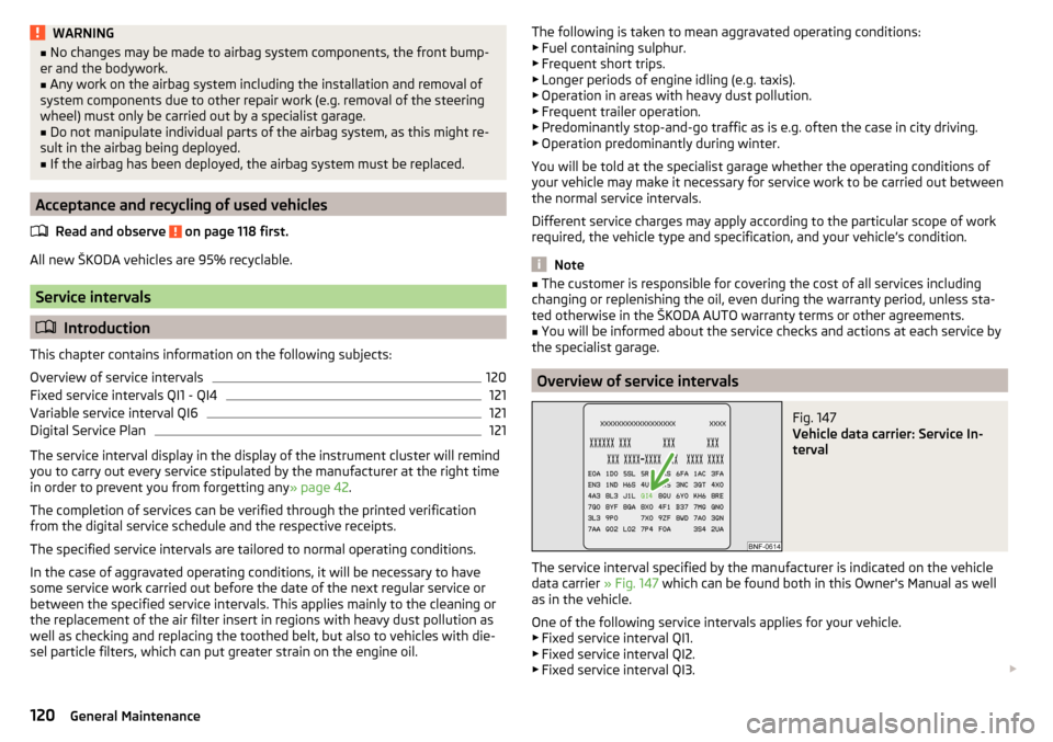
The service interval specified by the manufacturer is indicated on the vehicle
data carrier » Fig. 147 which can be found both in this Owner's Manual as well
as in the vehicle.
One of the following service intervals applies for your vehicle. ▶ Fixed service interval QI1.
▶ Fixed service interval QI2.
▶ Fixed service interval QI3.
120General Maintenance
Page 127 of 184
CAUTION■Move the scraper in one direction only, otherwise there is a risk of damage to
the glass surface.■
Do not remove snow / ice on the surface that is soiled (e.g. pea gravel, sand,
road salt) - there is a risk of damaging the surface.
■
Remove snow / ice carefully, otherwise there is a risk of damaging the labels
that have been fitted by the factory.
Caring for the interior
Read and observe
and on page 122 first.
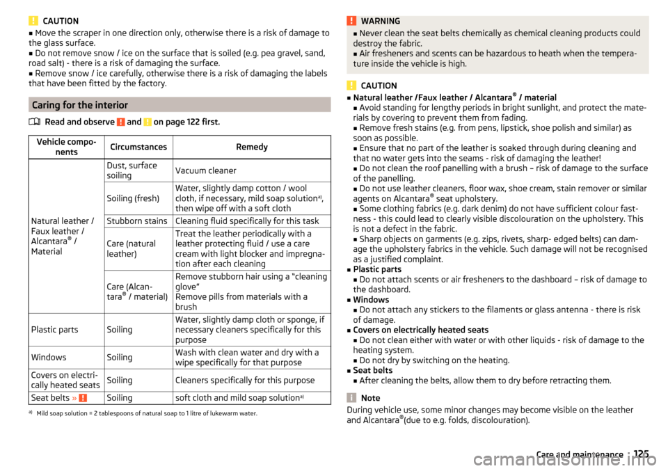
Vehicle compo- nentsCircumstancesRemedy
Natural leather /
Faux leather /
Alcantara ®
/
Material
Dust, surface
soilingVacuum cleanerSoiling (fresh)Water, slightly damp cotton / wool
cloth, if necessary, mild soap solution a)
,
then wipe off with a soft clothStubborn stainsCleaning fluid specifically for this taskCare (natural
leather)Treat the leather periodically with a
leather protecting fluid / use a care
cream with light blocker and impregna-
tion after each cleaningCare (Alcan-
tara ®
/ material)Remove stubborn hair using a “cleaning
glove”
Remove pills from materials with a
brushPlastic partsSoilingWater, slightly damp cloth or sponge, if
necessary cleaners specifically for this
purposeWindowsSoilingWash with clean water and dry with a
wipe specifically for that purposeCovers on electri-
cally heated seatsSoilingCleaners specifically for this purposeSeat belts » Soilingsoft cloth and mild soap solution a)a)
Mild soap solution = 2 tablespoons of natural soap to 1 litre of lukewarm water.
WARNING■
Never clean the seat belts chemically as chemical cleaning products could
destroy the fabric.■
Air fresheners and scents can be hazardous to heath when the tempera-
ture inside the vehicle is high.
CAUTION
■ Natural leather /Faux leather / Alcantara ®
/ material
■ Avoid standing for lengthy periods in bright sunlight, and protect the mate-
rials by covering to prevent them from fading.
■ Remove fresh stains (e.g. from pens, lipstick, shoe polish and similar) as
soon as possible.
■ Ensure that no part of the leather is soaked through during cleaning and
that no water gets into the seams - risk of damaging the leather!
■ Do not clean the roof panelling with a brush – risk of damage to the surface
of the panelling.
■ Do not use leather cleaners, floor wax, shoe cream, stain remover or similar
agents on Alcantara ®
seat upholstery.
■ Some clothing fabrics (e.g. dark denim) do not have sufficient colour fast-
ness - this could lead to clearly visible discolouration on the upholstery. This
is not a defect in the fabric.
■ Sharp objects on garments (e.g. zips, rivets, sharp- edged belts) can dam-
age the upholstery fabrics in the vehicle. Such damage will not be recognised
as a justified complaint.■
Plastic parts
■ Do not attach scents or air fresheners to the dashboard – risk of damage to
the dashboard.
■
Windows
■ Do not attach any stickers to the filaments or glass antenna - there is risk
of damage.
■
Covers on electrically heated seats ■ Do not clean either with water or with other liquids - risk of damage to the
heating system.
■ Do not dry by switching on the heating.
■
Seat belts
■ After cleaning the belts, allow them to dry before retracting them.
Note
During vehicle use, some minor changes may become visible on the leather
and Alcantara ®
(due to e.g. folds, discolouration).125Care and maintenance
Page 142 of 184

Do-it-yourself
Emergency equipment and self-help
Emergency equipment
Introduction
This chapter contains information on the following subjects:
Placement of the first aid kit and warning triangle
140
Location of reflective vest
140
fire extinguisher
140
Vehicle tool kit
141
Placement of the first aid kit and warning triangle
Fig. 160
Placing of the first-aid kit and the warning triangle
The following information is for the first aid kit and warning triangle from the
ŠKODA Original accessories valid.
Placing the first-aid kit
The first-aid box can be attached by a strap to the right-hand side of the boot
» Fig. 160 .
Placing of the warning triangle - variant 1
The warning triangle can be inserted into the recess under the loading edge
and secured with the fastener tape » Fig. 160 -
.
Placing of the warning triangle - variant 2
On vehicles with the vehicle battery in the boot warning triangle can be stow-
ed in a box under the floor covering in the luggage compartment » Fig. 160 -
.
WARNINGProperly secure the first aid kit and the warning triangle - there is a risk of
injury in the event of sudden braking or a vehicle collision.
Location of reflective vest
Fig. 161
Storage compartment for the re-
flective vest
The reflective vest can be stored in a bracket under the driver's seat » Fig. 161.
fire extinguisher
Fig. 162
Release the fire extinguisher
The fire extinguisher is attached by two straps in a holder underneath the driv-
er's seat.
›
To remove the fire extinguisher, release the safety catches on the two belts
in the direction of arrow » Fig. 162 and remove the fire extinguisher.
›
To secure , place the fire extinguisher back in the mount and secure with the
belts.
The Owner´s Manual is fitted next to the fire extinguisher.
Pay attention to the expiration date of the fire extinguisher. After this date,
the correct function of the device is not guaranteed.
140Do-it-yourself
Page 143 of 184
WARNINGAlways properly secure the fire extinguisher - there is a risk of injury in the
event of sudden braking or a vehicle collision.
Vehicle tool kit
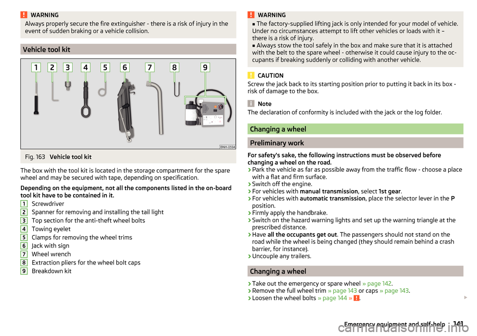
Fig. 163
Vehicle tool kit
The box with the tool kit is located in the storage compartment for the spare
wheel and may be secured with tape, depending on specification.
Depending on the equipment, not all the components listed in the on-board
tool kit have to be contained in it.
Screwdriver
Spanner for removing and installing the tail light
Top section for the anti-theft wheel bolts
Towing eyelet
Clamps for removing the wheel trims
Jack with sign
Wheel wrench
Extraction pliers for the wheel bolt caps
Breakdown kit
123456789WARNING■ The factory-supplied lifting jack is only intended for your model of vehicle.
Under no circumstances attempt to lift other vehicles or loads with it –
there is a risk of injury.■
Always stow the tool safely in the box and make sure that it is attached
with the belt to the spare wheel - otherwise it could cause injury to the oc-
cupants if breaking suddenly or colliding with another vehicle.
CAUTION
Screw the jack back to its starting position prior to putting it back in its box -
risk of damage to the box.
Note
The declaration of conformity is included with the jack or the log folder.
Changing a wheel
Preliminary work
For safety's sake, the following instructions must be observed before
changing a wheel on the road.
›
Park the vehicle as far as possible away from the traffic flow - choose a place
with a flat and firm surface.
›
Switch off the engine.
›
For vehicles with manual transmission , select 1st gear .
›
For vehicles with automatic transmission , place the selector lever in the P
position.
›
Firmly apply the handbrake.
›
Switch on the hazard warning lights and set up the warning triangle at the
prescribed distance.
›
Have all the occupants get out . The passengers should not stand on the
road while the wheel is being changed (they should remain behind a crash
barrier, for instance).
›
Uncouple any trailers.
Changing a wheel
›
Take out the emergency or spare wheel » page 142.
›
Remove the full wheel trim » page 143 or caps » page 143 .
›
Loosen the wheel bolts » page 144 » .
141Emergency equipment and self-help
Page 144 of 184

›Jack up the vehicle
» page 144 until the wheel that needs changing is clear of
the ground.›
Unscrew the wheel bolts and place them on a clean surface (cloth, paper,
etc.).
›
Remove the wheel carefully.
›
Attach the spare wheel and slightly screw on the wheel bolts.
›
Lower the vehicle.
›
Tighten the wheel bolts opposite each other using the wheel wrench (“pull- ing crossways”) » page 144.
›
Replace the wheel trim » page 143 and caps » page 143 .
When fitting unidirectional tyres, ensure that the direction of rotation is cor-
rect » page 136 .
All bolts must be clean and must turn easily. If screws are corroded and diffi-
cult to move, these must be replaced.
WARNING■ Undo the wheel bolts just a little (about one turn), provided the vehicle
has not yet been jacked up. Otherwise the wheel could come loose and fall
off – risk of injury.■
Under no circumstances must the bolts be greased or oiled - cause an ac-
cident.
Subsequent steps
After changing the wheel, the following work must be carried out.
›
Stow the replaced wheel in the well under the floor covering of the luggage
compartment and secure it with a nut.
›
Stow the tool kit in the space provided and secure using the band.
›
Check tyre pressure on the mounted wheel and adjust if necessary and, with
vehicles with tyre pressure monitoring, save the tyre pressure values in the
system » page 109 .
›
Have the tightening torque of the wheel bolts checked as soon as possible.
The prescribed tightening torque is 120 Nm.
Replace the damaged wheel or consult a specialist garage about repair op-
tions.
WARNINGTightening torque which is too high can damage the threads and this can
result in permanent deformation of the contact surfaces on the rim. Where
tightening torque is too low, the wheels may become loose while driving -
risk of accident. Therefore drive cautiously and only at a moderate speed
until the tightening torque has been checked.
Removing/stowing the emergency or spare wheel
Fig. 164
Take out the wheel
The wheel is located in a well under the floor covering in the luggage compart-
ment and is fixed in place with a screw.
Take out the wheel
›
Lift up the floor in the luggage compartment.
›
Loosen the retaining belt and take out the box with the tool kit.
›
Unscrew the nut in the direction of arrow » Fig. 164 and take out the wheel.
Stow the wheel
›
Place the wheel into the wheel well with the wheel rim pointing downward.
On vehicles with the vehicle battery in the boot, lay down the wheel with the
outer face upward.
›
Pull the fixing band through the opposite holes in the wheel rim.
›
Screw the nut in the opposite direction to the arrow until it stops » Fig. 164.
›
Place the box with the tool kit back inside the wheel and secure it with the
tape.
›
Fold back the floor in the luggage compartment.
142Do-it-yourself
Page 171 of 184
Index
A
ABS Operation
97
Warning light32
Acceptance and recycling of used vehicles
120
Accessories118
Adjusting Steering wheel
11
Adjusting the seats10
Adjustment Beam range
54
Advance warning / emergency braking37
Advice on tyre/wheel usage136
Air-conditioning system Air outlet vents
84
Airbag15
Adjustments and impairments to the airbag system
119
Deactivation18
Deployment16
Warning light32
Airbag system15
Air conditioning82
Air distribution control84
Climatronic83
Manual air conditioning82
Air distribution control84
Air outlet vents84
Alarm49
Trailer117
All-year tyres139
Anti-lock braking system (ABS)97
Anti-theft alarm system49
Trailer117
Anti-theft wheel bolts143
Armrest Front64
Rear65
Ashtray70
Assembling the tow bar, Step 1
113
tow bar, Step 2113
Assist systems96
Auto Check Control38
Automatic drive Selector lever
92
Automatic driving light control55
Automatic gearbox92
Kickdown94
Malfunction34
Selector lever-emergency unlocking151
Selector lever lock93
Starting-off and driving94
Tiptronic93
Warning light34
Automatic shutdown of consumers133
Automatic transmission Selector lever lock
93
AUX68
Avoiding damage to your vehicle95
B
Ball bar Standby position
112
Ball head Check fitting
114
Ready position112
Battery Change in key
150
Belts12
Belt tensioners14
Bluetooth See Owner´s Manual -Infotainment
6
Bonnet Closing129
Opening129
Boot Cargo element
79
Class N1 vehicles79
Hooks77
See boot lid51
Storage compartments78
Boot cover Parking position
78
Boot lid Automatic locking
51
Open/Close51
Brake Assist (HBA)98
Brake booster89
Brake fluid133
Check133
specification133
Brake pads New
89
Brake pedal (automatic transmission) Warning light
34
Brakes Brake booster
89
Brake fluid133
Braking and stabilisation systems96
Handbrake90
Information on braking89
Warning lights30
Brake system96
Braking Running in
94
Breakdown kit145
Breakdown service see Help in an emergency
8
Buttons in the door Electric window
52
169Index
Page 172 of 184
C
Camera See reversing camera
101
CAR See Owner´s Manual -Infotainment
6
Car battery Check condition
134
Cover134
Disconnecting and reconnecting135
Replacing135
Warning light34
Winter operation134
CAR button See Owner´s Manual -Infotainment
6
Car care Exterior
123
Interior125
Outside124
Car computer see multifunction display
39
Care and maintenance118
Cargo element79
Carrier81
Car washing122
Exterior123
Interior125
Washing122
Central locking45
Problems49
Central locking button47
Change battery
150
Changing Windscreen wiper blades
152
Changing a wheel141
Changing141
Changing gear Selector lever
92
Changing wheelsWheels141
Charging a vehicle battery135
Check Brake fluid
133
Engine oil131
Fit ball head properly114
Oil level131
Checking Battery status
134
Coolant132
Checks Statutory checks
118
Children and safety19
Child safety lock49
Child seat19
Classification21
Installation location21, 23
ISOFIX22, 23
on the front passenger seat20, 21
TOP TETHER24
Cigarette lighter70
Cleaning the vehicle Outside
124
Windows124
Climatronic82
air distribution control84
Automatic mode84
Operating elements83
Clothes hook73
Cockpit27
Lighting57
Comfort signalling55
COMING HOME56
Compartments67
Component protection119
Computer see multifunction display
39
Coolant131
Checking132
Refilling132
Temperature display29
Warning light35
CORNER See Fog lights with the CORNER function
56
Correct routing of seat belt
13
Correct seated position10
Correct seating position12
Cup holders69
D
DAY LIGHT See Daytime running lights
54
Daytime running lights54
Dazzle60
De-icing the windscreen and rear window59
Deactivation Airbag
18
Delayed locking of the boot lid See boot lid
51
Departure angle166
Diesel127
Diesel fuel127
Diesel particle filter (DPF)36
Digital Clock38
Digital Service Plan121
Dipstick131
Display Cardinal points
37
Coolant temperature29
Fuel level29
Gear changes38
In the instrument cluster37
MAXI DOT41
Service intervals42
170Index