brake light SKODA RAPID SPACEBACK 2016 1.G Owner's Guide
[x] Cancel search | Manufacturer: SKODA, Model Year: 2016, Model line: RAPID SPACEBACK, Model: SKODA RAPID SPACEBACK 2016 1.GPages: 184, PDF Size: 28.1 MB
Page 109 of 184
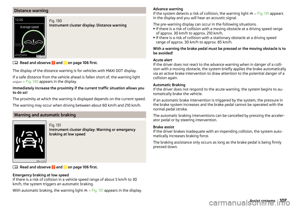
Distance warningFig. 130
Instrument cluster display: Distance warning
Read and observe and on page 106 first.
The display of the distance warning is for vehicles with MAXI DOT display.
If a safe distance from the vehicle ahead is fallen short of, the warning light
» Fig. 130 appears in the display.
Immediately increase the proximity if the current traffic situation allows you
to do so!
The proximity at which the warning is displayed depends on the current speed.
The warning may occur when driving between about 60 km/h and 210 km/h.
Warning and automatic braking
Fig. 131
Instrument cluster display: Warning or emergency
braking at low speed
Read and observe and on page 106 first.
Emergency braking at low speed
If there is a risk of collision in a vehicle speed range of about 5 km/h to 30 km/h, the system triggers an automatic braking.
With automatic braking, the warning light
» Fig. 131 appears in the display.
Advance warning
If the system detects a risk of collision, the warning light » Fig. 131 appears
in the display and you will hear an acoustic signal.
The pre-warning display can occur in the following situations.
▶ If there is a risk of collision with a moving obstacle at a driving speed range
of approx. 30 km/h to approx. 210 km/h.
▶ If there is a risk of collision with a stationary obstacle at a driving speed
range of approx. 30 km/h to approx. 85 km/h.
With a warning the brake pedal must be pressed or the moving obstacle is to
be avoided!
Acute alert
If the driver does not react to the advance warning when in danger of a colli-
sion with a moving obstacle, the system briefly applies the brake automatically
via an active brake intervention to draw attention to the potential danger of a
collision again.
Automatic Braking
If the driver does not respond to the acute warning, the system begins to au-
tomatically brake the vehicle.
If an automatic brake intervention is triggered by the system, the pressure in
the brake system increases and the brake pedal cannot be operated with the
normal pedal stroke.
The automatic braking interventions can be cancelled by pressing the acceler-
ator pedal or by steering intervention.
Brake assist
If the driver brakes inadequate with an impending collision, the system auto-
matically increases braking force.
The braking assistance only occurs as long as the brake pedal is being firmly
pressed down.107Assist systems
Page 118 of 184
Exterior mirrors
You should have additional exterior mirrors fitted if you are not able to see the
traffic behind the trailer using the standard rear-view mirrors.
Headlights
The front of the vehicle may lift up when a trailer (accessory) is being towed
and the headlights may dazzle other road users. Set the range of the head-
lights » page 54 .
Power supply of the trailer / accessory power system
In the electrical connection between the vehicle and trailer (accessory), the
trailer (accessories) is supplied with power from the vehicle (with ignition
switched on and off).
With the engine switched off, the vehicle battery is discharged by the connec-
ted consumers.
At low charge state of the vehicle battery, the power supply to the trailer (ac-
cessories) is interrupted.WARNING■ An improperly connected electrical installation of the trailer (accessories)
may result in an accident or serious injury from electrical shock.■
Do not make any adjustments to the electrical installation of the vehicle
and the trailer (accessories) - risk of an accident or serious injury from elec-
trical shock.
WARNING (Continued)■ After the electrical connection between the vehicle and trailer (accessory)
the trailer / accessory lights should be checked for function.■
Never use the securing eye to tow - risk of accident!
CAUTION
■ An improperly connected electrical installation of the trailer (accessories) can
lead to the inoperability of the vehicle electronics.■
The total power consumption of all the connected consumers to the trailer
power supply must not exceed 350 watts, otherwise there is a risk of damage
to the electrical system of the vehicle.
Loading a trailer
Correct the tyre inflation pressure on the vehicle for “full load” » page 137.
Distribution of the cargo
Distribute the cargo in the trailer in such a way that heavy items are located as
close to the trailer axle as possible. Secure the load from slipping.
The distribution of the weight is very poor if your vehicle is unladen and the
trailer is laden. Nevertheless, maintain a particularly low speed if you cannot
avoid driving with this combination.
WARNINGA sliding cargo can significantly adversely affect stability and driving safety
- there is a risk of accident!
Trailer load
The permissible trailer load must not be exceeded under any circumstances.Permissible trailer loadEngineGearboxPermissible trailer load, braked (kg)Permissible trailer load, unbraked (kg)Gradients of up to 12 %Gradients of up to 8% a)1.2 l/66 kW TSIMG9001000580DSG90010005901.2 ltr./81 kW TSIMG110012005901.4 ltr./92 kW TSIDSG12001200600DSG (Green tec)12001200610
116Driving
Page 119 of 184
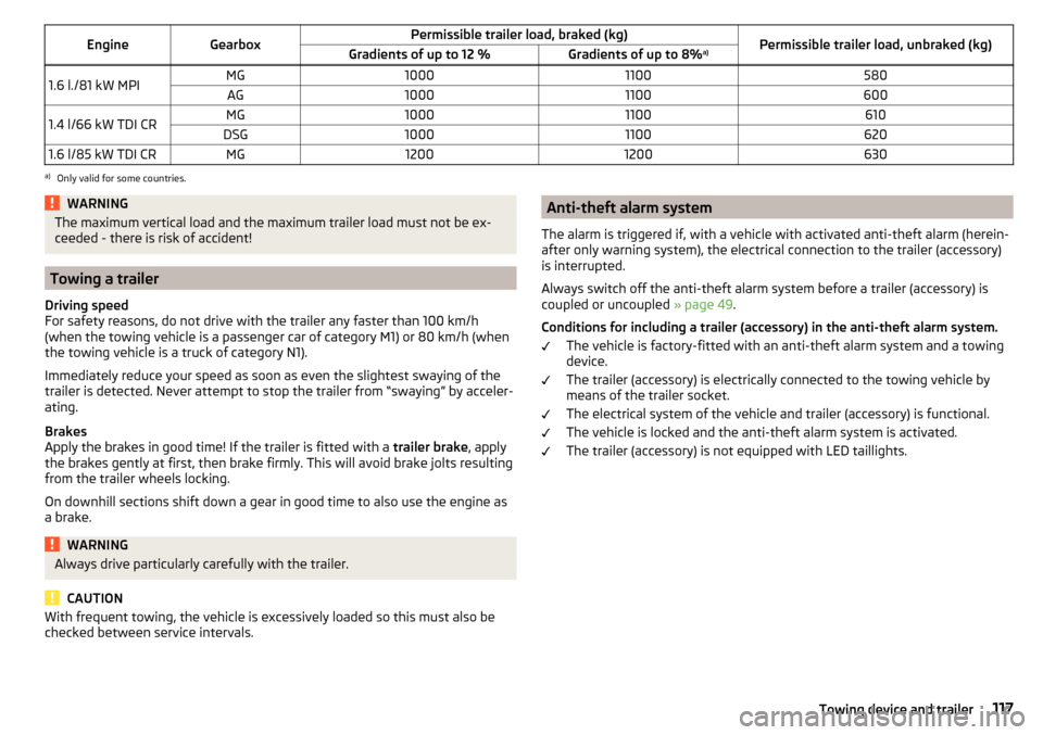
EngineGearboxPermissible trailer load, braked (kg)Permissible trailer load, unbraked (kg)Gradients of up to 12 %Gradients of up to 8%a)1.6 l./81 kW MPIMG10001100580AG100011006001.4 l/66 kW TDI CRMG10001100610DSG100011006201.6 l/85 kW TDI CRMG12001200630a)
Only valid for some countries.
WARNINGThe maximum vertical load and the maximum trailer load must not be ex-
ceeded - there is risk of accident!
Towing a trailer
Driving speed
For safety reasons, do not drive with the trailer any faster than 100 km/h
(when the towing vehicle is a passenger car of category M1) or 80 km/h (when
the towing vehicle is a truck of category N1).
Immediately reduce your speed as soon as even the slightest swaying of the
trailer is detected. Never attempt to stop the trailer from “swaying” by acceler-
ating.
Brakes
Apply the brakes in good time! If the trailer is fitted with a trailer brake, apply
the brakes gently at first, then brake firmly. This will avoid brake jolts resulting
from the trailer wheels locking.
On downhill sections shift down a gear in good time to also use the engine as
a brake.
WARNINGAlways drive particularly carefully with the trailer.
CAUTION
With frequent towing, the vehicle is excessively loaded so this must also be
checked between service intervals.Anti-theft alarm system
The alarm is triggered if, with a vehicle with activated anti-theft alarm (herein-
after only warning system), the electrical connection to the trailer (accessory)
is interrupted.
Always switch off the anti-theft alarm system before a trailer (accessory) is
coupled or uncoupled » page 49.
Conditions for including a trailer (accessory) in the anti-theft alarm system. The vehicle is factory-fitted with an anti-theft alarm system and a towing
device.
The trailer (accessory) is electrically connected to the towing vehicle by
means of the trailer socket.
The electrical system of the vehicle and trailer (accessory) is functional.
The vehicle is locked and the anti-theft alarm system is activated.
The trailer (accessory) is not equipped with LED taillights.117Towing device and trailer
Page 131 of 184
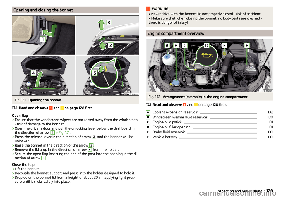
Opening and closing the bonnetFig. 151
Opening the bonnet
Read and observe
and on page 128 first.
Open flap
›
Ensure that the windscreen wipers are not raised away from the windscreen
- risk of damage to the bonnet.
›
Open the driver's door and pull the unlocking lever below the dashboard in
the direction of arrow
1
» Fig. 151 .
›
Press the release lever in the direction of arrow
2
and the bonnet will be
unlocked.
›
Raise the bonnet in the direction of the arrow
3
.
›
Remove the lid prop in the direction of arrow
4
from the holder.
›
Secure the open flap inserting the end of the post into the opening in the di-
rection of arrow
5
.
Close the flap
›
Lift the bonnet.
›
Decouple the bonnet support and press into the holder designed to hold it.
›
Drop down the bonnet lid from a height of about 20 cm applying light pres-
sure until it clicks safely into place.
WARNING■ Never drive with the bonnet lid not properly closed - risk of accident!■Make sure that when closing the bonnet, no body parts are crushed -
there is danger of injury!
Engine compartment overview
Fig. 152
Arrangement (example) in the engine compartment
Read and observe
and on page 128 first.
Coolant expansion reservoir
132
Windscreen washer fluid reservoir
130
Engine oil dipstick
131
Engine oil filler opening
131
Brake fluid reservoir
133
Vehicle battery
133ABCDEF129Inspecting and replenishing
Page 135 of 184

Brake fluidFig. 156
Brake fluid reservoir
Check the brake fluid under the following conditions.The vehicle is on a horizontal surface.
The engine is turned off.
Check brake fluid level - the brake fluid level must lie between the markings
“MIN” and “MAX” » Fig. 156.
Specification - the brake fluid must comply with the standard VW 501 14 (this
standard meets the requirements of FMVSS 116 DOT4).
WARNING■ The following instructions must be followed at all times when working on
the engine compartment » page 128.■
If the fluid level drops significantly within a short time or if it drops below
the “MIN” » Fig. 156mark, this may be an indication of a leak in the brake
system.
Stop driving - There is a risk of an accident! Seek help from a
specialist garage.
Note
■ The brake fluid is changed as part of a compulsory inspection service.■Too low brake fluid level is indicated by the warning light being shown on
the display of the instrument cluster as well as the corresponding message
» page 30 . We still recommend inspecting the brake fluid level in the reservoir
from time to time.Vehicle battery
Introduction
This chapter contains information on the following subjects:
Check condition
134
Charging
135
Disconnect/reconnect and change
135
The vehicle battery represents a power source for the motor to start and for the supply of electrical consumers in the car.
Depending on the engine, the vehicle battery is either in the engine compart-
ment or the luggage compartment.
Automatic shutdown of consumers - vehicle battery discharge protection
The on-board power supply system tries to prevent the vehicle battery from
discharging in the following ways when it is subject to heavy loading. ▶ By increasing the engine idle speed.
▶ Through the power limitation of certain consumers.
▶ By switching off some consumers (e.g. heated seats) for as long as necessa-
ry.
Warning symbols on the vehicle battery
SymbolMeaningAlways wear eye protection!Battery acid is severely caustic. Always wear gloves and eye pro-
tection!Keep fire, sparks, open flames and lit cigarettes well clear of the
vehicle battery!When charging the vehicle battery, a highly explosive gas mixture
is produced!Keep children away from the vehicle battery! 133Inspecting and replenishing
Page 143 of 184
WARNINGAlways properly secure the fire extinguisher - there is a risk of injury in the
event of sudden braking or a vehicle collision.
Vehicle tool kit
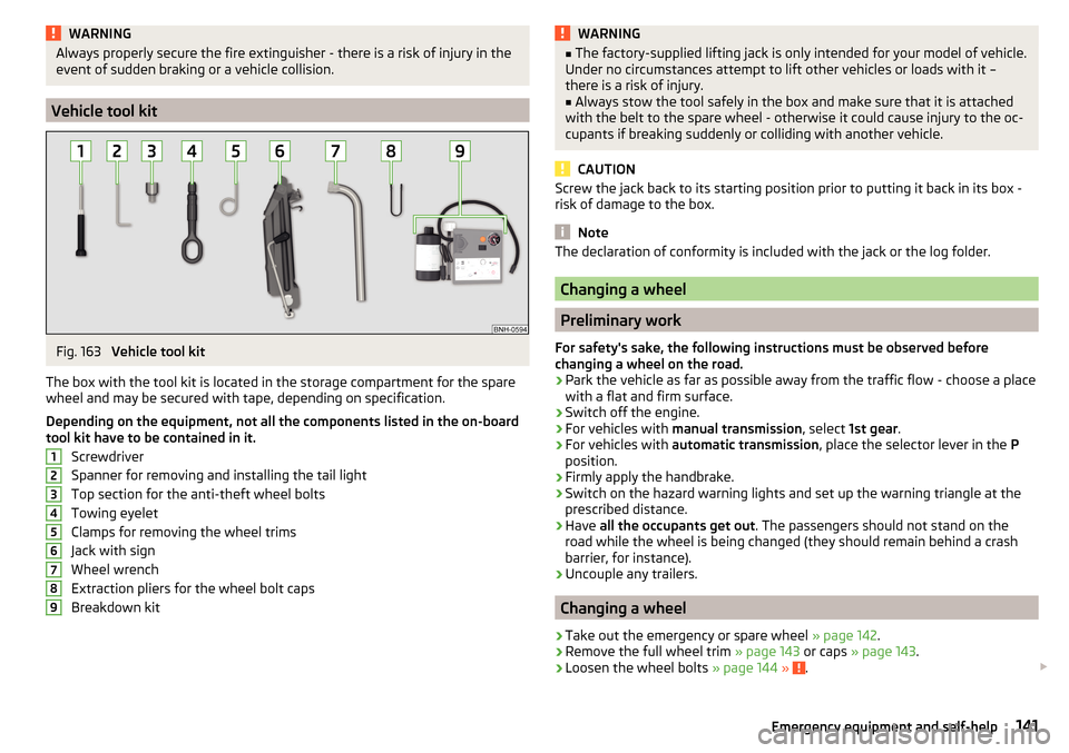
Fig. 163
Vehicle tool kit
The box with the tool kit is located in the storage compartment for the spare
wheel and may be secured with tape, depending on specification.
Depending on the equipment, not all the components listed in the on-board
tool kit have to be contained in it.
Screwdriver
Spanner for removing and installing the tail light
Top section for the anti-theft wheel bolts
Towing eyelet
Clamps for removing the wheel trims
Jack with sign
Wheel wrench
Extraction pliers for the wheel bolt caps
Breakdown kit
123456789WARNING■ The factory-supplied lifting jack is only intended for your model of vehicle.
Under no circumstances attempt to lift other vehicles or loads with it –
there is a risk of injury.■
Always stow the tool safely in the box and make sure that it is attached
with the belt to the spare wheel - otherwise it could cause injury to the oc-
cupants if breaking suddenly or colliding with another vehicle.
CAUTION
Screw the jack back to its starting position prior to putting it back in its box -
risk of damage to the box.
Note
The declaration of conformity is included with the jack or the log folder.
Changing a wheel
Preliminary work
For safety's sake, the following instructions must be observed before
changing a wheel on the road.
›
Park the vehicle as far as possible away from the traffic flow - choose a place
with a flat and firm surface.
›
Switch off the engine.
›
For vehicles with manual transmission , select 1st gear .
›
For vehicles with automatic transmission , place the selector lever in the P
position.
›
Firmly apply the handbrake.
›
Switch on the hazard warning lights and set up the warning triangle at the
prescribed distance.
›
Have all the occupants get out . The passengers should not stand on the
road while the wheel is being changed (they should remain behind a crash
barrier, for instance).
›
Uncouple any trailers.
Changing a wheel
›
Take out the emergency or spare wheel » page 142.
›
Remove the full wheel trim » page 143 or caps » page 143 .
›
Loosen the wheel bolts » page 144 » .
141Emergency equipment and self-help
Page 148 of 184
Preparing to use the breakdown kitRead and observe
on page 145 first.
For safety's sake, the following instructions must be observed before
undertaking a wheel repair on a road.
›
Park the vehicle as far as possible away from the traffic flow - choose a place
with a flat and firm surface.
›
Switch off the engine.
›
For vehicles with manual transmission , select 1st gear .
›
For vehicles with automatic transmission , place the selector lever in the P
position.
›
Firmly apply the handbrake.
›
Switch on the hazard warning lights and set up the warning triangle at the
prescribed distance.
›
Have all the occupants get out . While the repair is being carried out, the pas-
sengers should not stand on the road (instead they should remain behind a
crash barrier, for instance).
›
Uncouple any trailers.
Sealing and inflating tyres
Read and observe
on page 145 first.
Sealing
›
Unscrew the valve cap from the damaged tyre.
›
Insert the valve remover
2
» Fig. 170 on page 145 on the valve insert, so that
the valve insert fits into the slot of the valve remover.
›
Unscrew the valve insert and place it on a clean base (rag, paper etc.).
›
Forcefully shake bottle
10
» Fig. 170 on page 145 several times.
›
Firmly screw the inflation hose
3
onto the tyre inflater bottle
10
. The film on
the bottle cap is pierced.
›
Remove the plug from the inflation hose
3
and insert the bottle onto the
tyre valve.
›
Hold the bottle
10
with the bottom facing upwards and fill all of the sealing
agent from the tyre inflater bottle into the tyre.
›
Remove the filler plug from the tyre valve.
›
Screw in the valve insert with the valve remover
2
.
Inflating
›
Screw the tyre inflation hose
7
» Fig. 170 on page 145 firmly onto the tyre
valve.
› For vehicles with
manual transmission , set the lever in the neutral position.›On vehicles with automatic transmission , place the selector lever in the P
position.›
Start the engine.
›
Plug the connector
6
into the 12-volt socket » page 71.
›
Switch on the air compressor with the ON and OFF switch
9
.
›
Once tyre inflation pressure of 2.0-2.5 bar has been reached, turn off the air
compressor. Maximum run time of 6 minutes » .
›
If you cannot reach an air pressure of 2.0 - 2.5 bar, unscrew the tyre inflation
hose
7
from the tyre valve.
›
Drive the vehicle 10 metres forwards or backwards to allow the sealing agent
to “distribute” in the tyre.
›
Firmly screw the tyre inflation hose
7
back onto the tyre valve and repeat
the inflation process.
›
Stick the sticker
1
» Fig. 170 on page 145 on the dashboard in the driver's
field of view.
At a tyre inflation pressure of 2.0 – 2.5 bar, the journey can be continued at a
maximum speed of 80 km/h or 50 mph.
WARNING■ If the tire does not inflate at least. 2.0 bar, the damage is too great. The
sealing agent cannot be used to seal the tyre. Stop driving! Seek help
from a specialist garage.■
The tyre inflation hose and air compressor may get hot as the tyre is be-
ing inflated – there is a risk of burning.
CAUTION
Switch off the air compressor if it has been running for as much as 6 minutes –
risk of damage to the compressor! Allow the air compressor to cool a few mi-
nutes before switching it on again.
Information on driving with repaired tyres
Read and observe
on page 145 first.
The inflation pressure of the repaired tyre must be checked after driving for 10minutes.
If the tyre pressure is 1.3 bar or less
›
The tyre cannot be properly sealed with the breakdown kit.
Do not contin-
ue to drive! Seek help from a specialist garage.
146Do-it-yourself
Page 158 of 184
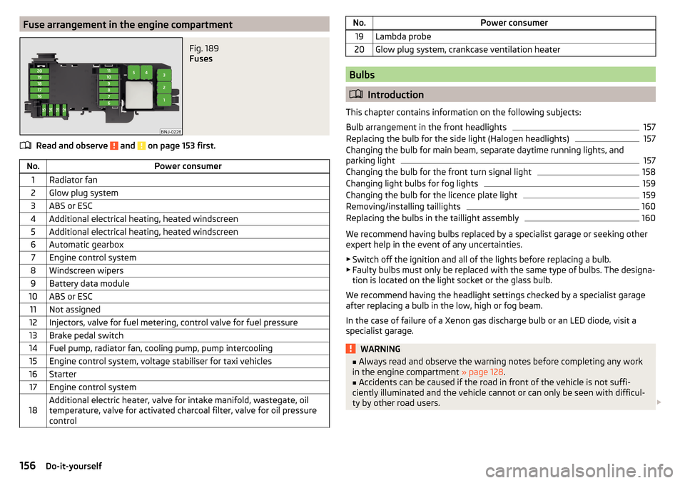
Fuse arrangement in the engine compartmentFig. 189
Fuses
Read and observe and on page 153 first.
No.Power consumer1Radiator fan2Glow plug system3ABS or ESC4Additional electrical heating, heated windscreen5Additional electrical heating, heated windscreen6Automatic gearbox7Engine control system8Windscreen wipers9Battery data module10ABS or ESC11Not assigned12Injectors, valve for fuel metering, control valve for fuel pressure13Brake pedal switch14Fuel pump, radiator fan, cooling pump, pump intercooling15Engine control system, voltage stabiliser for taxi vehicles16Starter17Engine control system18Additional electric heater, valve for intake manifold, wastegate, oil
temperature, valve for activated charcoal filter, valve for oil pressure
controlNo.Power consumer19Lambda probe20Glow plug system, crankcase ventilation heater
Bulbs
Introduction
This chapter contains information on the following subjects:
Bulb arrangement in the front headlights
157
Replacing the bulb for the side light (Halogen headlights)
157
Changing the bulb for main beam, separate daytime running lights, and
parking light
157
Changing the bulb for the front turn signal light
158
Changing light bulbs for fog lights
159
Changing the bulb for the licence plate light
159
Removing/installing taillights
160
Replacing the bulbs in the taillight assembly
160
We recommend having bulbs replaced by a specialist garage or seeking other
expert help in the event of any uncertainties.
▶ Switch off the ignition and all of the lights before replacing a bulb.
▶ Faulty bulbs must only be replaced with the same type of bulbs. The designa-
tion is located on the light socket or the glass bulb.
We recommend having the headlight settings checked by a specialist garage after replacing a bulb in the low, high or fog beam.
In the case of failure of a Xenon gas discharge bulb or an LED diode, visit a
specialist garage.
WARNING■ Always read and observe the warning notes before completing any work
in the engine compartment » page 128.■
Accidents can be caused if the road in front of the vehicle is not suffi-
ciently illuminated and the vehicle cannot or can only be seen with difficul-
ty by other road users.
156Do-it-yourself
Page 171 of 184
Index
A
ABS Operation
97
Warning light32
Acceptance and recycling of used vehicles
120
Accessories118
Adjusting Steering wheel
11
Adjusting the seats10
Adjustment Beam range
54
Advance warning / emergency braking37
Advice on tyre/wheel usage136
Air-conditioning system Air outlet vents
84
Airbag15
Adjustments and impairments to the airbag system
119
Deactivation18
Deployment16
Warning light32
Airbag system15
Air conditioning82
Air distribution control84
Climatronic83
Manual air conditioning82
Air distribution control84
Air outlet vents84
Alarm49
Trailer117
All-year tyres139
Anti-lock braking system (ABS)97
Anti-theft alarm system49
Trailer117
Anti-theft wheel bolts143
Armrest Front64
Rear65
Ashtray70
Assembling the tow bar, Step 1
113
tow bar, Step 2113
Assist systems96
Auto Check Control38
Automatic drive Selector lever
92
Automatic driving light control55
Automatic gearbox92
Kickdown94
Malfunction34
Selector lever-emergency unlocking151
Selector lever lock93
Starting-off and driving94
Tiptronic93
Warning light34
Automatic shutdown of consumers133
Automatic transmission Selector lever lock
93
AUX68
Avoiding damage to your vehicle95
B
Ball bar Standby position
112
Ball head Check fitting
114
Ready position112
Battery Change in key
150
Belts12
Belt tensioners14
Bluetooth See Owner´s Manual -Infotainment
6
Bonnet Closing129
Opening129
Boot Cargo element
79
Class N1 vehicles79
Hooks77
See boot lid51
Storage compartments78
Boot cover Parking position
78
Boot lid Automatic locking
51
Open/Close51
Brake Assist (HBA)98
Brake booster89
Brake fluid133
Check133
specification133
Brake pads New
89
Brake pedal (automatic transmission) Warning light
34
Brakes Brake booster
89
Brake fluid133
Braking and stabilisation systems96
Handbrake90
Information on braking89
Warning lights30
Brake system96
Braking Running in
94
Breakdown kit145
Breakdown service see Help in an emergency
8
Buttons in the door Electric window
52
169Index
Page 172 of 184
C
Camera See reversing camera
101
CAR See Owner´s Manual -Infotainment
6
Car battery Check condition
134
Cover134
Disconnecting and reconnecting135
Replacing135
Warning light34
Winter operation134
CAR button See Owner´s Manual -Infotainment
6
Car care Exterior
123
Interior125
Outside124
Car computer see multifunction display
39
Care and maintenance118
Cargo element79
Carrier81
Car washing122
Exterior123
Interior125
Washing122
Central locking45
Problems49
Central locking button47
Change battery
150
Changing Windscreen wiper blades
152
Changing a wheel141
Changing141
Changing gear Selector lever
92
Changing wheelsWheels141
Charging a vehicle battery135
Check Brake fluid
133
Engine oil131
Fit ball head properly114
Oil level131
Checking Battery status
134
Coolant132
Checks Statutory checks
118
Children and safety19
Child safety lock49
Child seat19
Classification21
Installation location21, 23
ISOFIX22, 23
on the front passenger seat20, 21
TOP TETHER24
Cigarette lighter70
Cleaning the vehicle Outside
124
Windows124
Climatronic82
air distribution control84
Automatic mode84
Operating elements83
Clothes hook73
Cockpit27
Lighting57
Comfort signalling55
COMING HOME56
Compartments67
Component protection119
Computer see multifunction display
39
Coolant131
Checking132
Refilling132
Temperature display29
Warning light35
CORNER See Fog lights with the CORNER function
56
Correct routing of seat belt
13
Correct seated position10
Correct seating position12
Cup holders69
D
DAY LIGHT See Daytime running lights
54
Daytime running lights54
Dazzle60
De-icing the windscreen and rear window59
Deactivation Airbag
18
Delayed locking of the boot lid See boot lid
51
Departure angle166
Diesel127
Diesel fuel127
Diesel particle filter (DPF)36
Digital Clock38
Digital Service Plan121
Dipstick131
Display Cardinal points
37
Coolant temperature29
Fuel level29
Gear changes38
In the instrument cluster37
MAXI DOT41
Service intervals42
170Index