dashboard warning lights SKODA RAPID SPACEBACK 2016 1.G Owner's Manual
[x] Cancel search | Manufacturer: SKODA, Model Year: 2016, Model line: RAPID SPACEBACK, Model: SKODA RAPID SPACEBACK 2016 1.GPages: 184, PDF Size: 28.1 MB
Page 19 of 184

The following airbags will be deployed in the event of a severe side collision.
▶ Front side airbag.
▶ Head airbag.
When an airbag is deployed, the following events occur. ▶ The hazard warning lights are switched on.
▶ All the doors are unlocked.
▶ The fuel supply to the engine is interrupted.
▶ The interior light comes on (if the automatic operation of the interior light is
switched on - position
).
When there is no air bag deployment?
With minor frontal and side collisions, rear collision, overturning of the vehicle
or vehicle roll-over there is no airbag deployment.
Safety instructions
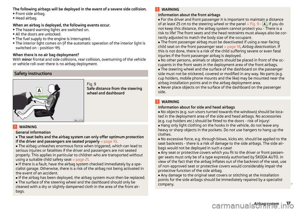
Fig. 9
Safe distance from the steering
wheel and dashboard
WARNINGGeneral information■The seat belts and the airbag system can only offer optimum protection
if the driver and passengers are seated properly » page 10 .■
The airbag unleashes enormous force when triggered, which can lead to
serious injuries or fatalities if the driver and passengers are not seated
properly. This applies in particular to children who are transported without
using a suitable child safety seat » page 21.
■
If there is a fault, have the airbag system checked immediately by a spe-
cialist garage. Otherwise, there is a risk of the airbag not being activated in
the event of an accident.
■
If the airbag has been deployed, the airbag system must then be replaced.
■
The surface of the steering wheel and the dashboard should only be
cleaned with a dry or slightly dampened cloth in the area of the front air-
bags.
WARNINGInformation about the front airbags■For the driver and front passenger it is important to maintain a distance
of at least 25 cm to the steering wheel or the panel » Fig. 9 - A
, If you do
not keep this distance, the airbag system cannot protect you - There is a
risk to life! The front seats and the head restraints must always also be cor-
rectly adjusted to match the body size of the occupant.
■
The front passenger airbag must be deactivated if using a rear-facing
child seat on the front passenger seat » page 18, Airbag deactivation . If
this is not done, there is a risk of the child suffering severe or even fatal
injuries if the front passenger airbag is deployed.
■
No other persons, animals or objects should be placed in front of the oc-
cupants in the front seats in the deployment area of the front airbags.
■
The steering wheel and the surface of the dashboard on the passenger
side must not be stickered, covered or modified in any way. No parts (e.g.
cup holders, mobile phone mounts and the like) may be mounted near the
airbag installation points and in the airbag deployment area.
■
Never place objects on the surface of the dashboard on the passenger
side.
WARNINGInformation about for side and head airbags■No objects (e.g. sun visors turned towards the windows) should be loca-
ted in the deployment area of the side and head airbags. No accessories
(e.g. cup holders etc.) should be fitted to the doors - risk of injury!■
Hang only light clothing on the hooks in the vehicle, do not leave any
heavy or sharp objects in the pockets. Do not use hangers to hang up the
clothes.
■
No excessive force, e.g. through blows, kicks etc. should be applied to the
seat backrests - there is a risk of damage to the side airbags. The side air-
bags would not be deployed in such a case!
■
Any seat or protective covers which you fit to the driver or front passen-
ger seats must only be of a type expressly authorised by ŠKODA AUTO. In
view of the fact that the airbag inflates out of the backrest of the seat, use
of non-approved seat or protective covers would considerably impair the
protective function of the side airbag.
■
Any damage to the original seat covers or stitching at the installation
points for the side airbags should be immediately repaired by a specialist
company.
17Airbag system
Page 148 of 184

Preparing to use the breakdown kitRead and observe
on page 145 first.
For safety's sake, the following instructions must be observed before
undertaking a wheel repair on a road.
›
Park the vehicle as far as possible away from the traffic flow - choose a place
with a flat and firm surface.
›
Switch off the engine.
›
For vehicles with manual transmission , select 1st gear .
›
For vehicles with automatic transmission , place the selector lever in the P
position.
›
Firmly apply the handbrake.
›
Switch on the hazard warning lights and set up the warning triangle at the
prescribed distance.
›
Have all the occupants get out . While the repair is being carried out, the pas-
sengers should not stand on the road (instead they should remain behind a
crash barrier, for instance).
›
Uncouple any trailers.
Sealing and inflating tyres
Read and observe
on page 145 first.
Sealing
›
Unscrew the valve cap from the damaged tyre.
›
Insert the valve remover
2
» Fig. 170 on page 145 on the valve insert, so that
the valve insert fits into the slot of the valve remover.
›
Unscrew the valve insert and place it on a clean base (rag, paper etc.).
›
Forcefully shake bottle
10
» Fig. 170 on page 145 several times.
›
Firmly screw the inflation hose
3
onto the tyre inflater bottle
10
. The film on
the bottle cap is pierced.
›
Remove the plug from the inflation hose
3
and insert the bottle onto the
tyre valve.
›
Hold the bottle
10
with the bottom facing upwards and fill all of the sealing
agent from the tyre inflater bottle into the tyre.
›
Remove the filler plug from the tyre valve.
›
Screw in the valve insert with the valve remover
2
.
Inflating
›
Screw the tyre inflation hose
7
» Fig. 170 on page 145 firmly onto the tyre
valve.
› For vehicles with
manual transmission , set the lever in the neutral position.›On vehicles with automatic transmission , place the selector lever in the P
position.›
Start the engine.
›
Plug the connector
6
into the 12-volt socket » page 71.
›
Switch on the air compressor with the ON and OFF switch
9
.
›
Once tyre inflation pressure of 2.0-2.5 bar has been reached, turn off the air
compressor. Maximum run time of 6 minutes » .
›
If you cannot reach an air pressure of 2.0 - 2.5 bar, unscrew the tyre inflation
hose
7
from the tyre valve.
›
Drive the vehicle 10 metres forwards or backwards to allow the sealing agent
to “distribute” in the tyre.
›
Firmly screw the tyre inflation hose
7
back onto the tyre valve and repeat
the inflation process.
›
Stick the sticker
1
» Fig. 170 on page 145 on the dashboard in the driver's
field of view.
At a tyre inflation pressure of 2.0 – 2.5 bar, the journey can be continued at a
maximum speed of 80 km/h or 50 mph.
WARNING■ If the tire does not inflate at least. 2.0 bar, the damage is too great. The
sealing agent cannot be used to seal the tyre. Stop driving! Seek help
from a specialist garage.■
The tyre inflation hose and air compressor may get hot as the tyre is be-
ing inflated – there is a risk of burning.
CAUTION
Switch off the air compressor if it has been running for as much as 6 minutes –
risk of damage to the compressor! Allow the air compressor to cool a few mi-
nutes before switching it on again.
Information on driving with repaired tyres
Read and observe
on page 145 first.
The inflation pressure of the repaired tyre must be checked after driving for 10minutes.
If the tyre pressure is 1.3 bar or less
›
The tyre cannot be properly sealed with the breakdown kit.
Do not contin-
ue to drive! Seek help from a specialist garage.
146Do-it-yourself
Page 155 of 184

Fuses and light bulbs
Fuses
Introduction
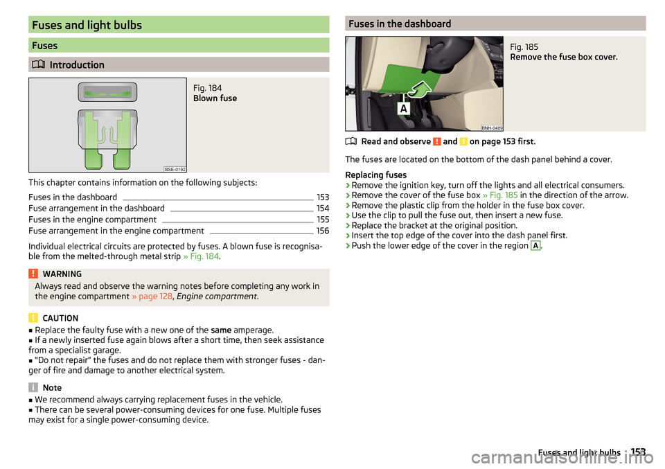
Fig. 184
Blown fuse
This chapter contains information on the following subjects:
Fuses in the dashboard
153
Fuse arrangement in the dashboard
154
Fuses in the engine compartment
155
Fuse arrangement in the engine compartment
156
Individual electrical circuits are protected by fuses. A blown fuse is recognisa-
ble from the melted-through metal strip » Fig. 184.
WARNINGAlways read and observe the warning notes before completing any work in
the engine compartment » page 128, Engine compartment .
CAUTION
■
Replace the faulty fuse with a new one of the same amperage.■If a newly inserted fuse again blows after a short time, then seek assistance
from a specialist garage.■
“Do not repair” the fuses and do not replace them with stronger fuses - dan-
ger of fire and damage to another electrical system.
Note
■ We recommend always carrying replacement fuses in the vehicle.■There can be several power-consuming devices for one fuse. Multiple fuses
may exist for a single power-consuming device.Fuses in the dashboardFig. 185
Remove the fuse box cover.
Read and observe and on page 153 first.
The fuses are located on the bottom of the dash panel behind a cover.
Replacing fuses
›
Remove the ignition key, turn off the lights and all electrical consumers.
›
Remove the cover of the fuse box » Fig. 185 in the direction of the arrow.
›
Remove the plastic clip from the holder in the fuse box cover.
›
Use the clip to pull the fuse out, then insert a new fuse.
›
Replace the bracket at the original position.
›
Insert the top edge of the cover into the dash panel first.
›
Push the lower edge of the cover in the region
A
.
153Fuses and light bulbs
Page 173 of 184

DisposalAcceptance and recycling of used vehicles120
Distance warning107
Warning light36
Door Child safety lock
49
Emergency locking151
Emergency locking of the driver's door150
Opening/Closing48
Door alarm37
Drive Driving through water
95
DriveGreen94
Driving Emissions
163
Fuel consumption163
Maximum speed167
through water95
E
Economical driving
94
EDL98
Electric power windows Operational faults
53
Electric window51
Buttons in the driver´s door52
Electronic Differential Lock (EDL)98
Electronic immobiliser86
Emergency Hazard warning light system
57
Jump-starting147
Selector lever-unlocking151
Starting / stopping the engine with the push of a button
87
Starting the engine / stopping with the push of a button
88
Towing the vehicle148
Towing the vehicle using the trailer device149
Tyre repair145
Unlocking/locking the door150
Unlocking / locking the door151
Emergency equipment Fire extinguisher
140
First aid kit140
Jack141
Reflective vest140
Vehicle tool kit141
Warning triangle140
Emergency spare Removing / stowing
142
Emission control system32
Emissions163
Engine Information messages
35
Running in94
Engine compartment128
Brake fluid133
Coolant131
Engine oil130
Overview129
Vehicle battery133
Windscreen washer fluid130
Engine drag torque control (MSR)97
Engine number162
engine oil specification
130
Engine oil130
Check131
Oil changing130
Refilling131
Warning light35
EPC32
ESC Operation
97
Warning light31
Extended warranty5
F
Fastening elements
76
Fatigue detection108
Films123
Fire extinguisher140
First aid kit140
Flashing55
Floor covering in the luggage compartment79
Fog lights Warning light
34
Fog lights/rear fog light56
Fog lights with the CORNER function56
Footmats91
refer to footmats91
Force limiter Window
53
Front Assist105
Deactivation/activation108
Distance warning107
Malfunctions108
Operation106
Radar sensor106
Warning and automatic braking107
Warning light36, 37
Front seats63
Fuel126
Diesel127
Fuel gauge29
refer to Fuel126
Refuelling126
Unleaded petrol126
Warning light33
Fuel consumption163
Fuel reserve33
Fuses153
in the dashboard153, 154
in the engine compartment155, 156
G
Gearbox Information messages
34
171Index