emergency towing SKODA RAPID SPACEBACK 2016 1.G Owner's Manual
[x] Cancel search | Manufacturer: SKODA, Model Year: 2016, Model line: RAPID SPACEBACK, Model: SKODA RAPID SPACEBACK 2016 1.GPages: 184, PDF Size: 28.1 MB
Page 5 of 184
Brake fluid133Vehicle battery133
Wheels
136
Wheels and tyres
136
Operating in winter conditions
139
Do-it-yourself
Emergency equipment and self-help
140
Emergency equipment
140
Changing a wheel
141
Breakdown kit
145
Jump-starting
147
Towing the vehicle
148
Remote - change battery
150
Emergency unlocking / unlocking of doors
150
Replacing windscreen wiper blades
151
Fuses and light bulbs
153
Fuses
153
Bulbs
156
Technical data
Technical data
162
Basic vehicle data
162
Vehicle-specific details per engine type
167
Index
3Table of Contents
Page 50 of 184
SafeLockRead and observe
and on page 46 first.
SafeLock prevents opening the doors from inside as well as window operation.
This makes an attempted break-in to the vehicle more difficult.
Activating
SafeLock is activated when the vehicle is locked from the outside.
This function is pointed out by the following message on the display of the in-
strument cluster after the ignition is switched off.
Check SAFELOCK! Log book!CHECK SAFELOCK
Activation display
When SafeLock is activated, the warning light in the driver's door flashes for 2
seconds in rapid succession, then starts to flash at longer intervals.
Deactivating
▶ By locking twice within 2 seconds.
▶ or: by deactivating the interior monitor and the towing protection
» page 50 .
The warning light in the driver door flashes rapidly for about 2 seconds, then
goes out and starts to flash at longer intervals after about 30 seconds.
If the vehicle is locked and the safe securing system is switched off, the door
can be opened separately from the inside by a single pull on opening lever.
The SafeLock switches on the next time the vehicle is locked.
WARNINGIf the car is locked and the safe securing system activated, no people must
remain in the car as it will then not be possible to either unlock a door or
open a window from the inside. The locked doors make it more difficult for
rescuers to get into the vehicle in an emergency – risk to life!
Individual settings
Read and observe
and on page 46 first.
The following functions of the central locking system can be set individually in
Infotainment » Owner´s Manual - Infotainment .
All doors
The function allows you to unlock all doors, the boot lid and the fuel filler flap.
Single door
The function allows you to unlock only the driver's door and the fuel filler flap
with the radio remote control. KESSY allows the unlocking of a single door
which is in the vicinity of the key, as well as the fuel filler flap. The other doors
and the boot lid are only unlocked once the door handle is unlocked or
touched.
Doors on a vehicle side
This function enables you to unlock both doors on the driver's side and the
fuel filler flap with the radio remote control unit. KESSY allows the unlocking of
both doors which are in the vicinity of the key, as well as the fuel filler flap. The
other doors and the boot lid are only unlocked once the door handle is un-
locked or touched.
Automatic locking/unlocking
This function enables the locking of all doors and the boot lid from a speed of
15 km / h. Opening the doors and the boot lid from the outside is not possible.
The renewed unlocking of the doors and the boot lid is carried out when the
ignition key is removed or when the door is opened from inside (depending on
the individual setting for the central locking system).
Opening/closing a door
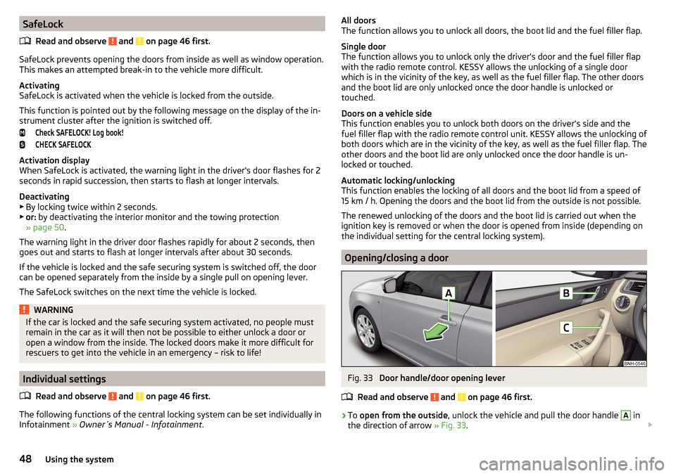
Fig. 33
Door handle/door opening lever
Read and observe
and on page 46 first.
›
To open from the outside , unlock the vehicle and pull the door handle
A
in
the direction of arrow » Fig. 33.
48Using the system
Page 51 of 184
›To
open from the inside pull the door opening lever B and push the door
away from you.›
To the lock from the inside , grab the handle
C
and close the door.
WARNING■
The door must be closed properly, otherwise it could open whilst the ve-
hicle is in motion - risk of fatality!■
Only open and close the door when there is no one in the opening/closing
range – risk of injury!
■
Never drive with the doors open - there is a risk of death!
■
An opened door can close automatically if there is a strong wind or the
vehicle is on an incline – risk of injury!
Child safety lock
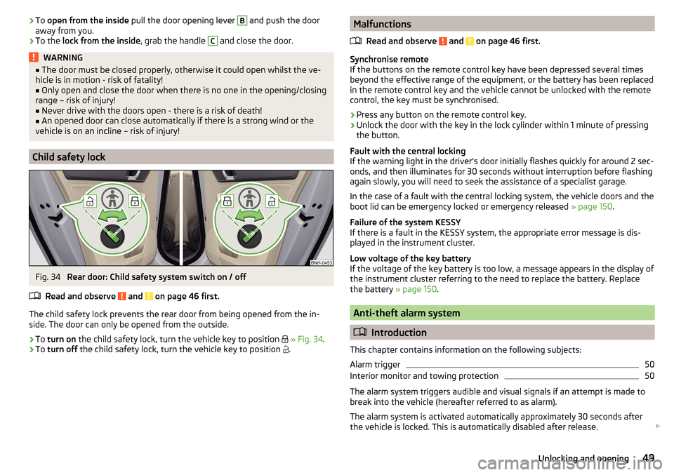
Fig. 34
Rear door: Child safety system switch on / off
Read and observe
and on page 46 first.
The child safety lock prevents the rear door from being opened from the in-
side. The door can only be opened from the outside.
›
To turn on the child safety lock, turn the vehicle key to position
» Fig. 34 .
›
To turn off the child safety lock, turn the vehicle key to position
.
Malfunctions
Read and observe
and on page 46 first.
Synchronise remote
If the buttons on the remote control key have been depressed several times
beyond the effective range of the equipment, or the battery has been replaced
in the remote control key and the vehicle cannot be unlocked with the remote
control, the key must be synchronised.
›
Press any button on the remote control key.
›
Unlock the door with the key in the lock cylinder within 1 minute of pressing the button.
Fault with the central locking
If the warning light in the driver's door initially flashes quickly for around 2 sec-
onds, and then illuminates for 30 seconds without interruption before flashing
again slowly, you will need to seek the assistance of a specialist garage.
In the case of a fault with the central locking system, the vehicle doors and the
boot lid can be emergency locked or emergency released » page 150.
Failure of the system KESSY
If there is a fault in the KESSY system, the appropriate error message is dis-
played in the instrument cluster.
Low voltage of the key battery
If the voltage of the key battery is too low, a message appears in the display of the instrument cluster referring to the need to replace the battery. Replace
the battery » page 150.
Anti-theft alarm system
Introduction
This chapter contains information on the following subjects:
Alarm trigger
50
Interior monitor and towing protection
50
The alarm system triggers audible and visual signals if an attempt is made to
break into the vehicle (hereafter referred to as alarm).
The alarm system is activated automatically approximately 30 seconds after the vehicle is locked. This is automatically disabled after release.
49Unlocking and opening
Page 113 of 184

Towing device and trailer
Hitch
Introduction
This chapter contains information on the following subjects:
Description
111
Adjusting the ready position
112
Check the setting of the standby position
112
Assembling the tow bar – Step 1
113
Assembling the tow bar – Step 2
113
Check proper fitting
114
Removing the tow bar – Step 1
114
Removing the tow bar – Step 2
114
Vertical load with mounted accessories
115
The maximum trailer nose weight when towing a trailer is 50 kg. Other infor-
mation (e.g. on the nameplate of the trailer device) provide only about the test
values of the device information.
WARNING■ Check that the tow bar is seated correctly and is secured in the mounting
recess before the start of every journey.■
When the ball rod is not used and properly secured in the receiving shaft,
this could be damaged or incomplete and must not be used - risk of acci-
dent.
■
Do not modify or adapt the towing device in any way.
■
Keep the mounting recess of the towing equipment clean at all times.
Such dirt prevents the ball head from being attached securely.
DescriptionFig. 135
Carrier for the towing device / tow bar
Read and observe
on page 111 first.
The ball rod is detachable and is located in the stowage compartment for the spare / emergency wheel.
Support for the towing device and tow bar » Fig. 135
Cap
Mounting recess
Protective cap
Locking ball
Centering
Hand wheel
Key
Lock cap
Red marking on the hand wheel
Tow bar
Green marking on the hand wheel
White marking on tow bar
123456789101112111Towing device and trailer
Page 143 of 184
WARNINGAlways properly secure the fire extinguisher - there is a risk of injury in the
event of sudden braking or a vehicle collision.
Vehicle tool kit
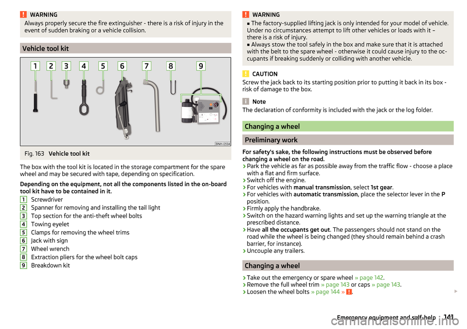
Fig. 163
Vehicle tool kit
The box with the tool kit is located in the storage compartment for the spare
wheel and may be secured with tape, depending on specification.
Depending on the equipment, not all the components listed in the on-board
tool kit have to be contained in it.
Screwdriver
Spanner for removing and installing the tail light
Top section for the anti-theft wheel bolts
Towing eyelet
Clamps for removing the wheel trims
Jack with sign
Wheel wrench
Extraction pliers for the wheel bolt caps
Breakdown kit
123456789WARNING■ The factory-supplied lifting jack is only intended for your model of vehicle.
Under no circumstances attempt to lift other vehicles or loads with it –
there is a risk of injury.■
Always stow the tool safely in the box and make sure that it is attached
with the belt to the spare wheel - otherwise it could cause injury to the oc-
cupants if breaking suddenly or colliding with another vehicle.
CAUTION
Screw the jack back to its starting position prior to putting it back in its box -
risk of damage to the box.
Note
The declaration of conformity is included with the jack or the log folder.
Changing a wheel
Preliminary work
For safety's sake, the following instructions must be observed before
changing a wheel on the road.
›
Park the vehicle as far as possible away from the traffic flow - choose a place
with a flat and firm surface.
›
Switch off the engine.
›
For vehicles with manual transmission , select 1st gear .
›
For vehicles with automatic transmission , place the selector lever in the P
position.
›
Firmly apply the handbrake.
›
Switch on the hazard warning lights and set up the warning triangle at the
prescribed distance.
›
Have all the occupants get out . The passengers should not stand on the
road while the wheel is being changed (they should remain behind a crash
barrier, for instance).
›
Uncouple any trailers.
Changing a wheel
›
Take out the emergency or spare wheel » page 142.
›
Remove the full wheel trim » page 143 or caps » page 143 .
›
Loosen the wheel bolts » page 144 » .
141Emergency equipment and self-help
Page 144 of 184

›Jack up the vehicle
» page 144 until the wheel that needs changing is clear of
the ground.›
Unscrew the wheel bolts and place them on a clean surface (cloth, paper,
etc.).
›
Remove the wheel carefully.
›
Attach the spare wheel and slightly screw on the wheel bolts.
›
Lower the vehicle.
›
Tighten the wheel bolts opposite each other using the wheel wrench (“pull- ing crossways”) » page 144.
›
Replace the wheel trim » page 143 and caps » page 143 .
When fitting unidirectional tyres, ensure that the direction of rotation is cor-
rect » page 136 .
All bolts must be clean and must turn easily. If screws are corroded and diffi-
cult to move, these must be replaced.
WARNING■ Undo the wheel bolts just a little (about one turn), provided the vehicle
has not yet been jacked up. Otherwise the wheel could come loose and fall
off – risk of injury.■
Under no circumstances must the bolts be greased or oiled - cause an ac-
cident.
Subsequent steps
After changing the wheel, the following work must be carried out.
›
Stow the replaced wheel in the well under the floor covering of the luggage
compartment and secure it with a nut.
›
Stow the tool kit in the space provided and secure using the band.
›
Check tyre pressure on the mounted wheel and adjust if necessary and, with
vehicles with tyre pressure monitoring, save the tyre pressure values in the
system » page 109 .
›
Have the tightening torque of the wheel bolts checked as soon as possible.
The prescribed tightening torque is 120 Nm.
Replace the damaged wheel or consult a specialist garage about repair op-
tions.
WARNINGTightening torque which is too high can damage the threads and this can
result in permanent deformation of the contact surfaces on the rim. Where
tightening torque is too low, the wheels may become loose while driving -
risk of accident. Therefore drive cautiously and only at a moderate speed
until the tightening torque has been checked.
Removing/stowing the emergency or spare wheel
Fig. 164
Take out the wheel
The wheel is located in a well under the floor covering in the luggage compart-
ment and is fixed in place with a screw.
Take out the wheel
›
Lift up the floor in the luggage compartment.
›
Loosen the retaining belt and take out the box with the tool kit.
›
Unscrew the nut in the direction of arrow » Fig. 164 and take out the wheel.
Stow the wheel
›
Place the wheel into the wheel well with the wheel rim pointing downward.
On vehicles with the vehicle battery in the boot, lay down the wheel with the
outer face upward.
›
Pull the fixing band through the opposite holes in the wheel rim.
›
Screw the nut in the opposite direction to the arrow until it stops » Fig. 164.
›
Place the box with the tool kit back inside the wheel and secure it with the
tape.
›
Fold back the floor in the luggage compartment.
142Do-it-yourself
Page 151 of 184
›If it is not possible to start the engine, switch on the ignition so that the
steering wheel does not lock and so that the turn signal lights, windscreen
wipers and windscreen washer system can be used.›
Take the vehicle out of gear or move the selector lever into position N if the
vehicle is fitted with an automatic gearbox.
›
Keep the tow rope taut at all times during the towing procedure.
WARNING■ Spiral tow ropes must not be used for towing » Fig. 173- , the towing
eye may unscrew out of the vehicle - risk of accident.■
The tow rope should not be twisted - there is a risk of accidents.
CAUTION
■ Do not tow-start the engine – risk of damaging the engine! The battery from
another vehicle can be used as a jump-start aid » page 147, Jump-starting .■
For off-road towing manoeuvres, there is a risk to both vehicles that the fas-
teners may become overloaded and damaged.
Note
We recommend that you use a tow rope from ŠKODA Original Accessories.
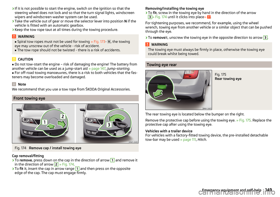
Front towing eye
Fig. 174
Remove cap / install towing eye
Cap removal/fitting
›
To remove , press down on the cap in the direction of arrow
1
and remove it
in the direction of arrow
2
» Fig. 174 .
›
To fit it, insert the cap in arrow range
1
and then press on the opposite
edge of the cap. The cap must engage firmly.
Removing/installing the towing eye›To fit, screw in the towing eye by hand in the direction of the arrow3
» Fig. 174 until it clicks into place » .
For tightening purposes, we recommend, for example, using the wheel
wrench, towing eye from another vehicle or a similar object that can be pushed through the eye.
›
To remove it, unscrew the towing eye in the opposite direction to arrow
3
.
WARNINGThe towing eye must always be firmly in place, otherwise the towing eye
could break whilst being towed.
Towing eye rear
Fig. 175
Rear towing eye
The rear towing eye is located below the bumper on the right.
Remove the protective cap before using the towing eye. » Fig. 175. Replace the
protective cap after using the towing eye.
Vehicles with a trailer device
For vehicles with a factory-fitted towing device, the pre-installed detachable
tow-bar may be used » page 111, Hitch .
149Emergency equipment and self-help
Page 156 of 184
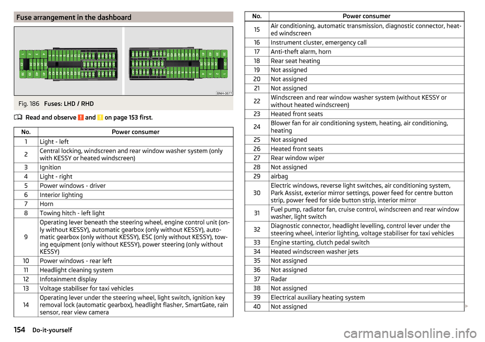
Fuse arrangement in the dashboardFig. 186
Fuses: LHD / RHD
Read and observe
and on page 153 first.
No.Power consumer1Light - left2Central locking, windscreen and rear window washer system (only
with KESSY or heated windscreen)3Ignition4Light - right5Power windows - driver6Interior lighting7Horn8Towing hitch - left light
9
Operating lever beneath the steering wheel, engine control unit (on-
ly without KESSY), automatic gearbox (only without KESSY), auto-
matic gearbox (only without KESSY), ESC (only without KESSY), tow-
ing equipment (only without KESSY), power steering (only without
KESSY)10Power windows - rear left11Headlight cleaning system12Infotainment display13Voltage stabiliser for taxi vehicles14Operating lever under the steering wheel, light switch, ignition key
removal lock (automatic gearbox), headlight flasher, SmartGate, rain
sensor, rear view cameraNo.Power consumer15Air conditioning, automatic transmission, diagnostic connector, heat-
ed windscreen16Instrument cluster, emergency call17Anti-theft alarm, horn18Rear seat heating19Not assigned20Not assigned21Not assigned22Windscreen and rear window washer system (without KESSY or
without heated windscreen)23Heated front seats24Blower fan for air conditioning system, heating, air conditioning,
heating25Not assigned26Heated front seats27Rear window wiper28Not assigned29airbag30Electric windows, reverse light switches, air conditioning system,
Park Assist, exterior mirror settings, power feed for centre button
strip, power feed for side button strip, interior mirror31Fuel pump, radiator fan, cruise control, windscreen and rear window
washer, light switch32Diagnostic connector, headlight levelling, control lever under the
steering wheel, interior lighting, voltage stabiliser for taxi vehicles33Engine starting, clutch pedal switch34Heated windscreen washer jets35Not assigned36Not assigned37Radar38Not assigned39Electrical auxiliary heating system40Not assigned 154Do-it-yourself
Page 165 of 184

Maximum permissible front axle load
Maximum permissible rear axle load
Vehicle identification number (VIN)
The vehicle identification number - VIN (vehicle body number) is stamped into
the engine compartment on the right hand suspension strut dome. This num-
ber is also located on a sign on the lower left hand edge below the windscreen
(together with a VIN bar code), and on the type plate.
The VIN number can also be displayed in Infotainment » Owner´s Manual - In-
fotainment .
Engine number
The engine number (three-digit identifier and serial number) is stamped on the
engine block.
Supplementary Information (applies to Russia)
The full type approval number of the means of transport is indicated in the
registration documents, field 17.
Maximum permissible towed weight
The listed maximum allowable trailer weight is only valid for altitudes up to
1000 m above sea level.
The engine output falls as altitude increases, as does the vehicle's climbing
power. Therefore, for every additional 1,000 m in height (or part), the maximum
permissible towed weight must be reduced by 10%.
The towed weight is made up of the actual weights of the loaded towing vehi-
cle and the loaded trailer.WARNINGDo not exceed the specified maximum permissible weights – risk of acci-
dent and damage!
Operating weight
This value is only a guide value and corresponds to the lowest possible operat-
ing weight without any equipment added that would also increase the weight
(e.g. air conditioning, emergency or spare wheel etc.). It also includes a weight
allowance for the driver (75 kg), the weight of the operating fluids, the tool kit
and a fuel tank filled to 90 % capacity.
1011Operating weightEngineGearboxOperating weight (kg)1.2 l/66 kW TSIMG1160DSG11941.2 ltr./81 kW TSIMG11801.4 ltr./92 kW TSIDSG1212DSG (Green tec)12211.6 l./81 kW MPIMG1160AG12001.4 l/66 kW TDI CRMG1229DSG12501.6 l/85 kW TDI CRMG1275
Note
If required, you can find out the precise weight of your vehicle at a specialist
garage.
Payload
It is possible to calculate the approximate maximum payload from the differ-
ence between the permissible total weight and the operating weight.
The payload consists of the following weights.
▶ The weight of the passengers.
▶ The weight of all items of luggage and other loads.
▶ The weight of the roof, including the roof rack system.
▶ The weight of the equipment that is excluded from the operating weight.
▶ Trailer draw-bar load when towing a trailer (max. 50 kg).
Measurement of fuel consumption and CO
2 emissions according to
ECE Regulations and EU Directives
The data on fuel consumption and CO 2 emissions were not available at the
time of going to press.
The data on fuel consumption and CO 2 emissions are given on the ŠKODA
websites or in the sales and technical vehicle documentation.
The measurement of the intra-urban cycle begins with a cold start of the en-
gine. Afterwards urban driving is simulated.
163Technical data
Page 173 of 184
DisposalAcceptance and recycling of used vehicles120
Distance warning107
Warning light36
Door Child safety lock
49
Emergency locking151
Emergency locking of the driver's door150
Opening/Closing48
Door alarm37
Drive Driving through water
95
DriveGreen94
Driving Emissions
163
Fuel consumption163
Maximum speed167
through water95
E
Economical driving
94
EDL98
Electric power windows Operational faults
53
Electric window51
Buttons in the driver´s door52
Electronic Differential Lock (EDL)98
Electronic immobiliser86
Emergency Hazard warning light system
57
Jump-starting147
Selector lever-unlocking151
Starting / stopping the engine with the push of a button
87
Starting the engine / stopping with the push of a button
88
Towing the vehicle148
Towing the vehicle using the trailer device149
Tyre repair145
Unlocking/locking the door150
Unlocking / locking the door151
Emergency equipment Fire extinguisher
140
First aid kit140
Jack141
Reflective vest140
Vehicle tool kit141
Warning triangle140
Emergency spare Removing / stowing
142
Emission control system32
Emissions163
Engine Information messages
35
Running in94
Engine compartment128
Brake fluid133
Coolant131
Engine oil130
Overview129
Vehicle battery133
Windscreen washer fluid130
Engine drag torque control (MSR)97
Engine number162
engine oil specification
130
Engine oil130
Check131
Oil changing130
Refilling131
Warning light35
EPC32
ESC Operation
97
Warning light31
Extended warranty5
F
Fastening elements
76
Fatigue detection108
Films123
Fire extinguisher140
First aid kit140
Flashing55
Floor covering in the luggage compartment79
Fog lights Warning light
34
Fog lights/rear fog light56
Fog lights with the CORNER function56
Footmats91
refer to footmats91
Force limiter Window
53
Front Assist105
Deactivation/activation108
Distance warning107
Malfunctions108
Operation106
Radar sensor106
Warning and automatic braking107
Warning light36, 37
Front seats63
Fuel126
Diesel127
Fuel gauge29
refer to Fuel126
Refuelling126
Unleaded petrol126
Warning light33
Fuel consumption163
Fuel reserve33
Fuses153
in the dashboard153, 154
in the engine compartment155, 156
G
Gearbox Information messages
34
171Index