engine SKODA ROOMSTER 2006 1.G Owner's Guide
[x] Cancel search | Manufacturer: SKODA, Model Year: 2006, Model line: ROOMSTER, Model: SKODA ROOMSTER 2006 1.GPages: 274, PDF Size: 48.64 MB
Page 42 of 274
Unlocking and locking41
Using the systemSafetyDriving TipsGeneral MaintenanceBreakdown assistanceTechnical Data
Service Partner. You should, however, proceed as follows if you
wish to replace the battery yourself:
– Fold open the key.
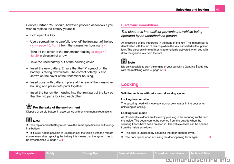
– Use a screwdriver to carefully lever off the front part of the key
⇒ page 40, fig. 19 from the transmitter housing .
– Take off the cover of the transmitter housing ⇒page 40,
fig. 20 in direction of arrow.
– Take the used battery out of the housing cover.
– Insert the new battery. Ensure that the “+” symbol on the battery is facing downwards. The correct polarity is also
shown on the cover of the transmitter housing.
– Insert cover with battery in place at the rear of the transmitter housing and press both parts together.
– Insert the transmitter housing into the front part of the key so that the two parts lock into each other.
For the sake of the environment
Dispose of an old battery in accordance with environmental regulations.
Note
•The replacement battery must have the same specification as the orig-
inal battery.
•If it is still not be possible to unlock or lock the vehicle with the remote
control even after replacing the battery this means that the system has to
be synchronised ⇒page 49.
Electronic immobiliser
The electronic immobiliser prevents the vehicle being
operated by an unauthorised person.
An electronic chip is integrated in the head of the key. The immobiliser is
deactivated with the aid of this chip when the key is inserted in the ignition
lock. The electronic immobiliser is automatically activated when you with-
draw the ignition key from the lock.
Note
It is only possible to start the engine of your car with a Genuine Škoda key
with the matching code ⇒page 32.
Locking
Valid for vehicles without a central locking system:
Locking from outside
The securing head will move upwards or downwards in the door when
unlocking or locking.
Locking from inside
All closed vehicle doors are locked by pressing in the securing knobs from
the inside. The doors cannot be opened from the outside when the
securing knobs have been pressed in. The vehicle doors can be opened
from the inside as follows:
•The door is unlocked by actuating the door-opening lever.
•The door opens upon actuating the door-opening lever again.
AAAB
NKO 20 A05.book Page 41 Wednesday, June 21, 2006 1:42 PM
Page 49 of 274
Unlocking and locking
48
Remote control*
Description
You can use the remote control:
•to unlock and lock the car,
•unlock the tailgate.
The transmitter with the battery is housed in the handle of the master key.
The receiver is located in the interior of the car. The operating range of the
remote control is 10 metres but this range can be reduced if the batteries
are weak.
The master key has a fold-open key bit which can be used for unlocking
and locking the car manually and also for starting the engine.
If a lost key is replaced or if the receiver unit has been repaired or a new
unit installed, it is then necessary for a Škoda Service Partner to initialise
the system. Only after this is it possible to again use the remote control.
Note
•The remote control is automatically deactivated when the ignition is
switched on.
•The operation of the remote control may temporarily be affected by
interference from transmitters close to the car and which operate in the
same frequency range (e.g. mobile phone, TV transmitter).
•The battery must be replaced if the central locking or anti-theft alarm
system does react to the remote control at less than 3 metres away. We
recommend having the battery replaced by a Škoda Service Partner.
Unlocking and locking car
The radio-operated key differs according to the equipment
installed on the vehicle.
Unlocking th e vehicle
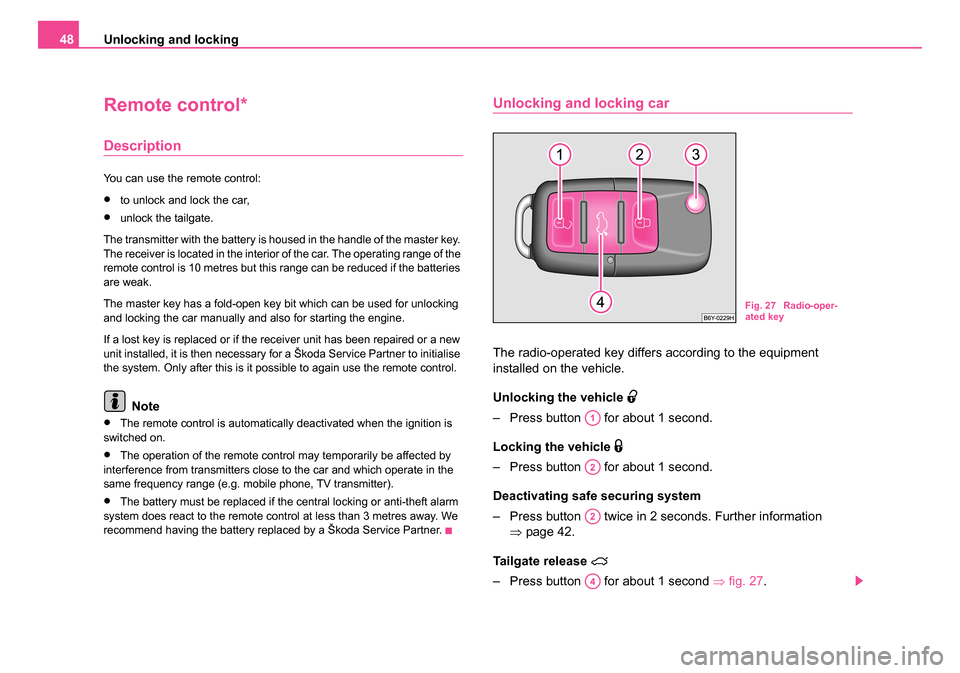
– Press button for about 1 second.
Locking the vehicle
– Press button for about 1 second.
Deactivating safe securing system
– Press button twice in 2 seconds. Further information ⇒page 42.
Tailgate release
– Press button for about 1 second ⇒fig. 27 .
Fig. 27 Radio-oper-
ated key
A1
A2
A2
A4
NKO 20 A05.book Page 48 Wednesday, June 21, 2006 1:42 PM
Page 57 of 274
Lights and Visibility
56
– Turn the light switch into position O ⇒page 55, fig. 32 .
– Switch on the switch for daylight driving lights ⇒page 55,
fig. 33 .
– After switching on the ignition the side lights are switched on.
– After starting the engine the low beam is switched on.
Switching off daylight driving lights*
– Switch off the switch for daylight driving lights ⇒page 55,
fig. 33 .
– Turn the light switch to the position side lights
or low beam
⇒ page 55, fig. 32 .
Low beam comes on only if the ignition is switched on. The low beam is
switched off automatically when the engine is started and after switching
the ignition off; only the side lights come on.
On models fitted with right-hand steering* the position of certain
switches differs from that shown in ⇒page 55, fig. 32 . The symbols which
mark the switch positions are identical, however.
WARNING
Never drive with side lights on - risk of accident! The side lights are
not bright enough to light up the road sufficiently in front of you or
to be seen by other oncoming traffic. In this case, always switch on
the low beam when it is dark or if visibility is poor.
Note
•An audible warning will sound if you withdraw the ignition key and open
the driver's door when the vehicle lights are still on.
•The acoustic warning signal is switched off over the door contact when
the driver's door is closed (ignition off). The vehicle can be parked with the
side lights on.
•If you park the car for a lengthy period, we recommend switching off all
lights, or leaving only the side lights switched on.
•The switching on of the described lights should only be undertaken in
accordance with the legal requirements.
•In the event of cool or humid weather conditions, the headlights can be
misted up from inside.
−The temperature difference between interior and external area of
the headlight lenses is decisive.
− When the driving lights are switched on, the light outlet surfaces are
free from mist after a short period. The headlight lenses can possibly
mist up at the border areas.
− It also concerns reverse light and turn signal lights.
− This mist has no influence on the life of the lighting system.
Cornering lights*
For a better cornering illumination the cornering lights are controlled in the
optimal position in line with the vehicle speed and the steering angle.
If the warning light
flashes for 1 minute while driving or after switching
on the ignition and a warning signal sounds, a fault is confirmed.
NKO 20 A05.book Page 56 Wednesday, June 21, 2006 1:42 PM
Page 63 of 274
Lights and Visibility
62
Note
We recommend having the bulb replaced by a specialist garage.
Luggage compartment light
The lighting comes on automatically when the tailgate is opened. The
luggage compartment lighting will switch off again automatically if the boot
lid remains open for more than about 30 minutes.
Visibility
Rear window heater
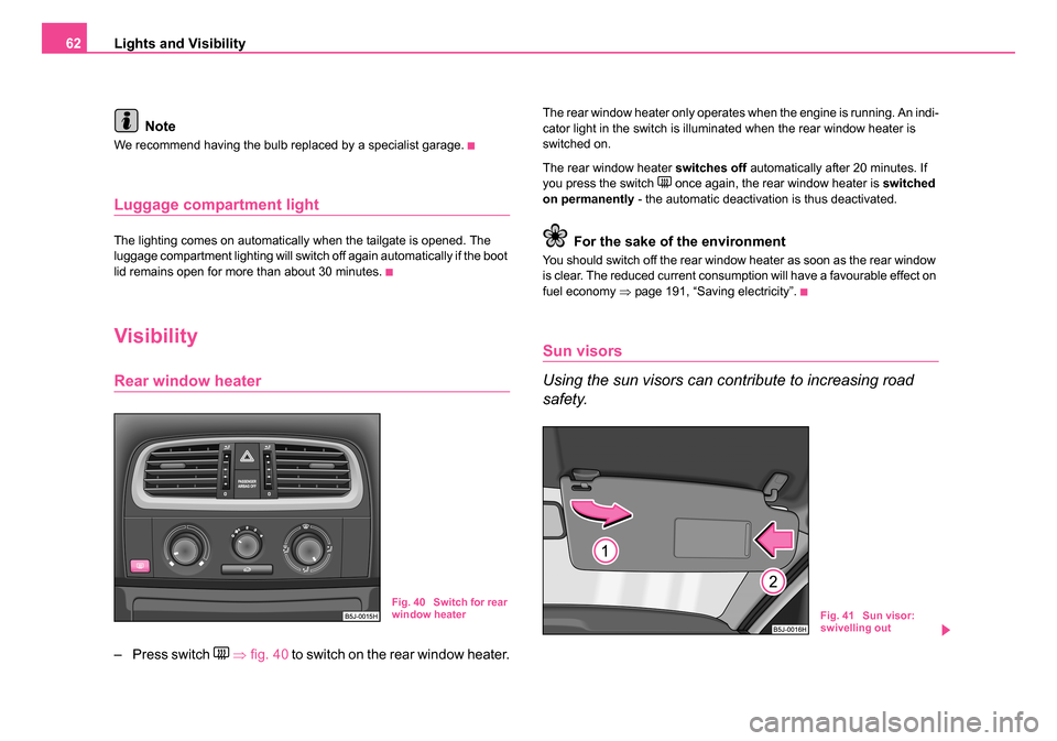
– Press switch ⇒ fig. 40 to switch on the rear window heater.
The rear window heater only operates when the engine is running. An indi-
cator light in the switch is illuminated when the rear window heater is
switched on.
The rear window heater switches off automatically after 20 minutes. If
you press the switch
once again, the rear window heater is switched
on permanently - the automatic deactivation is thus deactivated.
For the sake of the environment
You should switch off the rear window heater as soon as the rear window
is clear. The reduced current consumption will have a favourable effect on
fuel economy ⇒page 191, “Saving electricity”.
Sun visors
Using the sun visors can contribute to increasing road
safety.
Fig. 40 Switch for rear
window heaterFig. 41 Sun visor:
swivelling out
NKO 20 A05.book Page 62 Wednesday, June 21, 2006 1:42 PM
Page 68 of 274
Lights and Visibility67
Using the systemSafetyDriving TipsGeneral MaintenanceBreakdown assistanceTechnical Data
Adjusting the right-hand exterior mirror*
– Turn the rotary knob to position
. The movement of the mirror
surface is identical to the movement of the rotary knob.
The exterior mirror heater only operates when the engine is running.
WARNING
•Convex (curved outward) or a spherical exterior mirrors
increase the vision field. They do, however, make objects appear
smaller in the mirror. These mirror s are only of limited use, there-
fore, for estimating distances to the following vehicles.
•Use whenever possible the interior rear mirror, for estimating
the distances to the following vehicles.
Note
•Do not touch the surfaces of the exterior mirrors if the exterior mirror
heater is switched on.
•You can set the exterior mirrors by hand, if the power setting function
fails at any time, by pressing on the edge of the mirror surface.
•Contact your specialist garage if a fault exists with the power setting of
the exterior mirrors.
NKO 20 A05.book Page 67 Wednesday, June 21, 2006 1:42 PM
Page 72 of 274
Seats and Stowage71
Using the systemSafetyDriving TipsGeneral MaintenanceBreakdown assistanceTechnical Data
Heating the front seats*
The seating and leaning surfaces of the driver and front
passenger seat can be heated when the ignition is switched on.
Front seats
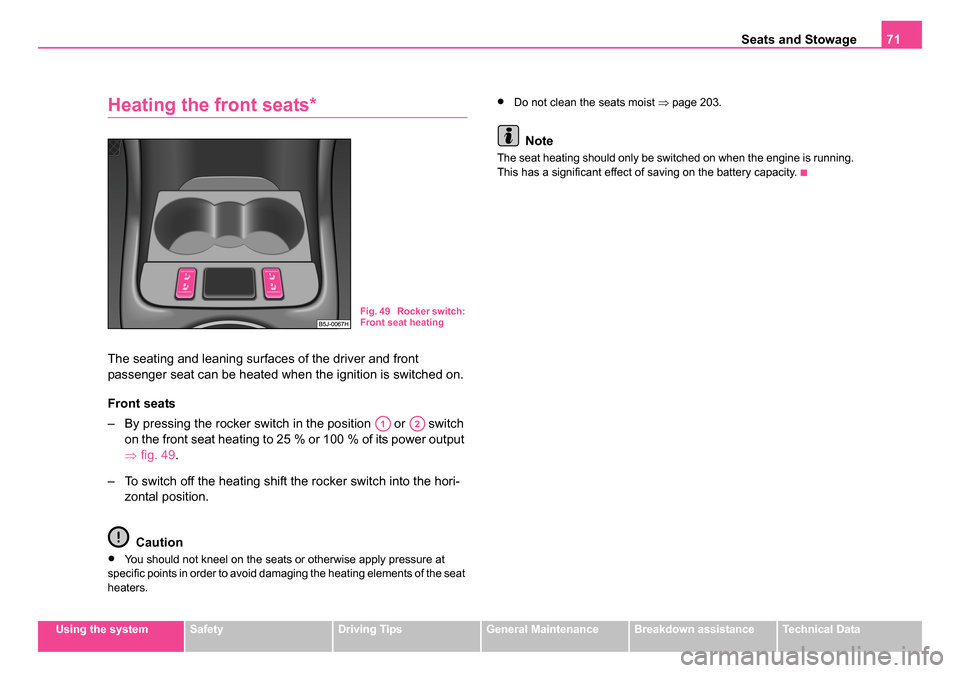
– By pressing the rocker switch in the position or switch
on the front seat heating to 25 % or 100 % of its power output
⇒fig. 49 .
– To switch off the heating shift the rocker switch into the hori- zontal position.
Caution
•You should not kneel on the seats or otherwise apply pressure at
specific points in order to avoid damaging the heating elements of the seat
heaters.
•Do not clean the seats moist ⇒page 203.
Note
The seat heating should only be switched on when the engine is running.
This has a significant effect of saving on the battery capacity.
Fig. 49 Rocker switch:
Front seat heating
A1A2
NKO 20 A05.book Page 71 Wednesday, June 21, 2006 1:42 PM
Page 90 of 274
Seats and Stowage89
Using the systemSafetyDriving TipsGeneral MaintenanceBreakdown assistanceTechnical Data
– Insert the plug of the electrical appliance into the socket of the
cigarette lighter.
The 12 volt power socket can also be used to supply power to electrical
accessories with a power uptake up to 180 watts.
WARNING
•Take care when using the cigarette lighter! Not paying proper
attention or incorrect use the cigarette lighter in an uncontrolled
manner may result in burns.
•The cigarette lighter and the power socket also operates when
the ignition is switched off or th e ignition key withdrawn. This is
why you should never leave children unattended in the vehicle!
Caution
Only use matching plugs, which fulfils the DIN - ISO Standard 4165, to
avoid damaging the power sockets.
Note
Connecting electrical components when the engine is not running
will drain the battery of the vehicle - risk of battery draining!
Power socket in the luggage compartment
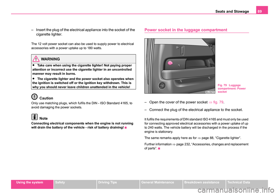
– Open the cover of the power socket ⇒fig. 79 .
– Connect the plug of the electrical appliance to the socket.
It fulfils the requirements of DIN standard ISO 4165 and must only be used
for connecting approved electrical accessories with a power uptake of up
to 240 watts. The vehicle battery will be discharged in the process if the
engine is stationary.
The same remarks apply here as for ⇒page 88, “Cigarette lighter”.
Further information ⇒page 232, “Accessories, changes and replacement
of parts”.
Fig. 79 Luggage
compartment: Power
socket
NKO 20 A05.book Page 89 Wednesday, June 21, 2006 1:42 PM
Page 97 of 274
Heating and air conditioning system
96
Heating and air conditioning system
Heating
Using the system
The heating system delivers air into the interior of the
vehicle and warms it as required.
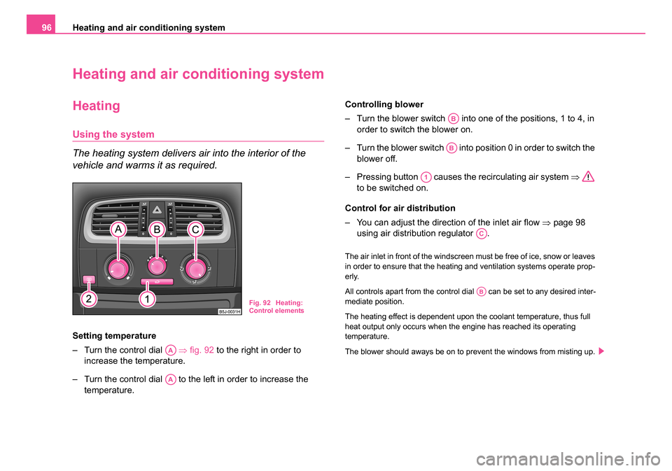
Setting temperature
– Turn the control dial ⇒fig. 92 to the right in order to
increase the temperature.
– Turn the control dial to the left in order to increase the temperature. Controlling blower
– Turn the blower switch into one of the positions, 1 to 4, in
order to switch the blower on.
– Turn the blower switch into position 0 in order to switch the blower off.
– Pressing button causes the recirculating air system ⇒
to be switched on.
Control for air distribution
– You can adjust the direction of the inlet air flow ⇒page 98
using air distribution regulator .
The air inlet in front of the windscreen must be free of ice, snow or leaves
in order to ensure that the heating and ventilation systems operate prop-
erly.
All controls apart from the control dial can be set to any desired inter-
mediate position.
The heating effect is dependent upon the coolant temperature, thus full
heat output only occurs when the engine has reached its operating
temperature.
The blower should aways be on to prevent the windows from misting up.
Fig. 92 Heating:
Control elements
AA
AA
AB
AB
A1
AC
AB
NKO 20 A05.book Page 96 Wednesday, June 21, 2006 1:42 PM
Page 100 of 274
Heating and air conditioning system 99
Using the systemSafetyDriving TipsGeneral MaintenanceBreakdown assistanceTechnical Data
Redirecting air flow
– The horizontal as well as the vertical direction of the air flow is
set with the handle in the middle of the air outlet vents.
You can set the air supply to the individual vents with the air distribution
control ⇒page 96, fig. 92 . Air outlet vents 3 and 4 can also be opened
or closed individually.
Unwarmed or cooled air will flow out of the opened air outlet vents
according to the setting of the control dial ⇒page 96, fig. 92 and
according to atmospheric conditions.
Climatic (semi-automatic air
conditioning system)*
Description
Climatic is a combined cooling and heating system with
electronic control of the convenience temperature in the
vehicle interior. It makes it possible to optimally control the
air temperature at any season of the year.
Description of the Climatic
It is important for your safety and for your driving comfort that the Climatic
is operating properly.
The air conditioning system operates when switch ⇒page 100,
fig. 94 is pressed and the following conditions are met:
•engine running,
•outside temperature above +2 °C and
•blower switch switched on (positions 1 to 4).
If the cooling system is switched on, the temperature and air humidity
drops in the vehicle. The wellbeing of the occupants of the car is enhanced
as a result of this particularly at high outside temperatures and a high air
humidity. The system prevents the windows misting up during the cold
season of the year.
The heating effect is dependent upon the coolant temperature, thus full
heat output only occurs when the engine has reached its operating
temperature.
It is possible to briefly activate recirculated air mode in order to enhance
the cooling effect ⇒.
Air at a temperature of about 5°C may flow out of the vents under certain
circumstances when the cooling system is operating. Lengthy and uneven
distribution of the air flow out of the vents (in particular at the leg area) and
large differences in temperature, for example when getting out of the
vehicle, can result in chills in sensitive persons.
The air inlet in front of the windscreen must be free of ice, snow or leaves
in order to ensure that the heating and cooling systems operate properly.
After switching on the cooling Condensation from the evaporator of the
air conditioning may drip down and form a puddle below the vehicle. This
is quite normal and not an indication of a leak!
WARNING
•For your own safety and that of other road users, ensure that all
the windows are free of ice, snow and misting. Please familiarize
yourself about how to correctly operate the heating and ventilation
systems, how to demist and defrost the windows, as well as with
the cooling mode.
•You should not leave recirculated air mode on over a longer
period of time, as “stale” air may result in fatigue in the driver and
occupants, divert your attention and also cause the windows to
AC
AA
ACAE
NKO 20 A05.book Page 99 Wednesday, June 21, 2006 1:42 PM
Page 104 of 274
Heating and air conditioning system 103
Using the systemSafetyDriving TipsGeneral MaintenanceBreakdown assistanceTechnical Data
Air outlet vents
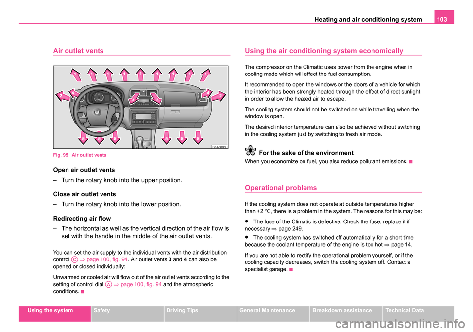
Fig. 95 Air outlet vents
Open air outlet vents
– Turn the rotary knob into the upper position.
Close air outlet vents
– Turn the rotary knob into the lower position.
Redirecting air flow
– The horizontal as well as the vertical direction of the air flow is
set with the handle in the middle of the air outlet vents.
You can set the air supply to the individual vents with the air distribution
control ⇒page 100, fig. 94 . Air outlet vents 3 and 4 can also be
opened or closed individually:
Unwarmed or cooled air will flow out of the air outlet vents according to the
setting of control dial ⇒page 100, fig. 94 and the atmospheric
conditions.
Using the air conditioni ng system economically
The compressor on the Climatic uses power from the engine when in
cooling mode which will effect the fuel consumption.
It recommended to open the windows or the doors of a vehicle for which
the interior has been strongly heated through the effect of direct sunlight
in order to allow the heated air to escape.
The cooling system should not be switched on while travelling when the
window is open.
The desired interior temperature can also be achieved without switching
in the cooling system just by switching to fresh air mode.
For the sake of the environment
When you economize on fuel, you also reduce pollutant emissions.
Operational problems
If the cooling system does not operate at outside temperatures higher
than +2 °C, there is a problem in the system. The reasons for this may be:
•The fuse of the Climatic is defective. Check the fuse, replace it if
necessary ⇒page 249.
•The cooling system has switched off automatically for a short time
because the coolant temperature of the engine is too hot ⇒page 14.
If you are not able to rectify the operational problem yourself, or if the
cooling capacity decreases, switch the cooling system off. Contact a
specialist garage.
AC
AA
NKO 20 A05.book Page 103 Wednesday, June 21, 2006 1:42 PM