service indicator SKODA ROOMSTER 2006 1.G Owner's Manual
[x] Cancel search | Manufacturer: SKODA, Model Year: 2006, Model line: ROOMSTER, Model: SKODA ROOMSTER 2006 1.GPages: 274, PDF Size: 48.64 MB
Page 6 of 274
Contents5
Contents
Layout of this Owner's Manual
(explanations)
. . . . . . . . . . . . . . . . . . .
Using the system . . . . . . . . . . . . . . .
Cockpit . . . . . . . . . . . . . . . . . . . . . . . . . . . . . . .
General view . . . . . . . . . . . . . . . . . . . . . . . . .
Instruments and Indicator/Warning LightsGeneral view of the instrument cluster . . . . . .
Engine revolutions counter . . . . . . . . . . . . . . .
Coolant temperature gauge* . . . . . . . . . . . . .
Fuel gauge* . . . . . . . . . . . . . . . . . . . . . . . . . .
Counter for distance driven . . . . . . . . . . . . . .
Service Interval Display . . . . . . . . . . . . . . . . .
Digital clock . . . . . . . . . . . . . . . . . . . . . . . . . .
Multi-functional indicator (onboard computer)*
Information display* . . . . . . . . . . . . . . . . . . . .
Auto Check Control . . . . . . . . . . . . . . . . . . . .
Warning lights . . . . . . . . . . . . . . . . . . . . . . . . .
Unlocking and locking . . . . . . . . . . . . . . . . . .
Key . . . . . . . . . . . . . . . . . . . . . . . . . . . . . . . . .
Locking . . . . . . . . . . . . . . . . . . . . . . . . . . . . . .
Child safety lock . . . . . . . . . . . . . . . . . . . . . . .
Central locking system* . . . . . . . . . . . . . . . . .
Remote control* . . . . . . . . . . . . . . . . . . . . . . .
Anti-theft alarm system* . . . . . . . . . . . . . . . . .
Interior monitor* and Towing protection* . .
Power windows* . . . . . . . . . . . . . . . . . . . . . . .
Panorama roof* . . . . . . . . . . . . . . . . . . . . . . .
Lights and Visibility. . . . . . . . . . . . . . . . . . . . .
Lights . . . . . . . . . . . . . . . . . . . . . . . . . . . . . . .
Interior lighting . . . . . . . . . . . . . . . . . . . . . . . . Visibility . . . . . . . . . . . . . . . . . . . . . . . . . . . . .
Windshield wiper and wash system . . . . . . . .
Rear mirror . . . . . . . . . . . . . . . . . . . . . . . . . . .
Seats and Stowage . . . . . . . . . . . . . . . . . . . .
Front seats . . . . . . . . . . . . . . . . . . . . . . . . . . .
Head restraints . . . . . . . . . . . . . . . . . . . . . . . .
Heating the front seats* . . . . . . . . . . . . . . . . .
Rear seats . . . . . . . . . . . . . . . . . . . . . . . . . . .
Pedals . . . . . . . . . . . . . . . . . . . . . . . . . . . . . .
Luggage compartment . . . . . . . . . . . . . . . . . .
Bicycle carrier* . . . . . . . . . . . . . . . . . . . . . . . .
The roof luggage rack system* . . . . . . . . . . .
Front cup holder . . . . . . . . . . . . . . . . . . . . . . .
Rear cup holder* . . . . . . . . . . . . . . . . . . . . . .
Note holder . . . . . . . . . . . . . . . . . . . . . . . . . .
Ashtray* . . . . . . . . . . . . . . . . . . . . . . . . . . . . .
Cigarette lighter* and power sockets* . . . . . .
Storage compartments . . . . . . . . . . . . . . . . . .
Heating and air conditioning system . . . . .
Heating . . . . . . . . . . . . . . . . . . . . . . . . . . . . . .
Climatic (semi-automatic air conditioning
system)* . . . . . . . . . . . . . . . . . . . . . . . . . . . . .
Climatronic (automatic air conditioning)* . . . .
Starting-off and Driving. . . . . . . . . . . . . . . . .
Setting steering wheel position* . . . . . . . . . . .
Ignition lock . . . . . . . . . . . . . . . . . . . . . . . . . .
Starting the engine . . . . . . . . . . . . . . . . . . . . .
Switching off the engine . . . . . . . . . . . . . . . . .
Shifting (manual gearbox) . . . . . . . . . . . . . . .
Handbrake . . . . . . . . . . . . . . . . . . . . . . . . . . .
Parking aid* . . . . . . . . . . . . . . . . . . . . . . . . . .
Cruise control system (CCS)* . . . . . . . . . . . .
Automatic gearbox. . . . . . . . . . . . . . . . . . . . .
6-speed automatic gearbox* . . . . . . . . . . . . .
Communication . . . . . . . . . . . . . . . . . . . . . . .
Operating the radio . . . . . . . . . . . . . . . . . . . .
Radio and mobile phone operation . . . . . . . .
Universal telephone preinstallation with voice
control* . . . . . . . . . . . . . . . . . . . . . . . . . . . . .
Inserting the mobile phone and adapter . . . .
Mobile phone operation . . . . . . . . . . . . . . . . .
Voice commands . . . . . . . . . . . . . . . . . . . . . .
Enter PIN code . . . . . . . . . . . . . . . . . . . . . . .
Select number . . . . . . . . . . . . . . . . . . . . . . . .
Repeat last call . . . . . . . . . . . . . . . . . . . . . . .
Phone voice phonebook* . . . . . . . . . . . . . . . .
Bluetooth™* . . . . . . . . . . . . . . . . . . . . . . . . .
Mobile phones and two-way radio systems . .
Input AUX-IN* . . . . . . . . . . . . . . . . . . . . . . . .
CD changer* . . . . . . . . . . . . . . . . . . . . . . . . .
Safety. . . . . . . . . . . . . . . . . . . . . . . . . . . . . .
Passive Safety . . . . . . . . . . . . . . . . . . . . . . . .
Basic information . . . . . . . . . . . . . . . . . . . . . .
Correct seated position . . . . . . . . . . . . . . . . .
Seat belts. . . . . . . . . . . . . . . . . . . . . . . . . . . . .
Why seat belts? . . . . . . . . . . . . . . . . . . . . . . .
The physical principle of a frontal collision . .
Important safety information regarding the use
of seat belts . . . . . . . . . . . . . . . . . . . . . . . . . .
How are seat belts correctly fastened? . . . . .
Belt tensioner . . . . . . . . . . . . . . . . . . . . . . . . .
8
9
11
11
13
13
14
14
14
15
16
17
17
22
24
27
39
39
41
42
42
48
49
50
51
54
55
55
60 62
63
66
68
68
70
71
72
76
77
81
85
86
86
87
87
88
90
96
96
99
104
109
109 11 0111
11 2
11 3
11 4
11 5
11 6 11 9
11 9
126
126
127
128
129
130
131
132
133
133
134
136
138
138
139
141
141
141
143
147
147
148
149
150
152
NKO 20 A05.book Page 5 Wednesday, June 21, 2006 1:42 PM
Page 14 of 274
Instruments and Indicator/Warning Lights13
Using the systemSafetyDriving TipsGeneral MaintenanceBreakdown assistanceTechnical Data
Instruments and Indicator/Warning Lights
General view of the instrument cluster
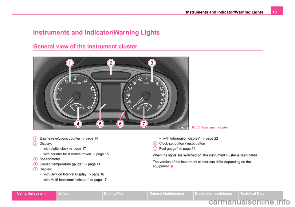
Engine revolutions counter ⇒page 14
Display:
− with digital clock ⇒page 17
− with counter for distance driven ⇒page 15
Speedometer
Coolant temperature gauge* ⇒page 14
Display:
− with Service Interval Display ⇒page 16
− with Multi-functional indicator* ⇒page 17 −
with Information display* ⇒page 22
Clock-set button / reset button
Fuel gauge* ⇒page 14
When the lights are switched on, the instrument cluster is illuminated.
The version of the instrument cluster can differ depending on the
equipment.
Fig. 2 Instrument cluster
A1
A2
A3
A4
A5
A6
A7
NKO 20 A05.book Page 13 Wednesday, June 21, 2006 1:42 PM
Page 16 of 274
Instruments and Indicator/Warning Lights15
Using the systemSafetyDriving TipsGeneral MaintenanceBreakdown assistanceTechnical Data
The fuel tank has a capacity of about 55 litres. The warning symbol
in
the instrument cluster lights up when the pointer reaches the reserve
marking. There are now about 7 litres of fuel remaining in the tank. This
symbol is a reminder for you, that you must refuel.
The following will be displayed in the information display*: PLEASE REFUEL
A peep sounds as an additional warning signal.
Caution
Never run the fuel tank completely empty! An irregular fuel supply can
result in poor ignition or misfiring. Unburnt fuel may get into the exhaust
system and damage the catalytic converter.
Counter for distance driven
The distance which you have driven with your vehicle is shown in kilome-
tres (km). On certain model versions, the readout is shown in “miles”.
The kilometer counter for distance driven is shown on the display when
the ignition is switched off. The trip counter for distance driven is shown
on the display after switching on the ignition. You can then switch over to
the counter display with the reset button.
Reset button
By briefly pressing the reset button ⇒page 13, fig. 2 you can switch
over from the trip counter to the kilometer counter. In order to recognize
which counter for the distance driven is shown on the display at that
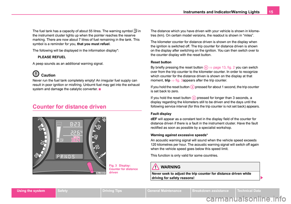
moment, trip ⇒ fig. 3 appears after the trip counter.
If you hold the reset button pressed for about 1 second, the trip counter
is set back to zero.
If you hold the reset button pressed for longer than 3 seconds, a
display regarding the kilometers still to be driven and the days until the
following service interval (for this the trip counter is not set back) appears.
Fault display
dEF will appear as a constant text in the display field of the counter for
distance driven if there is a fault in the instrument cluster. Have the fault
rectified as soon as possible by a specialist workshop.
Warning against excessive speeds*
An acoustic warning signal will sound when the vehicle speed exceeds
120 kilometres per hour. The acoustic warning signal will switch off again
when the vehicle speed goes below this speed limit.
This function is only valid for some countries.
WARNING
Never seek to adjust the trip counter for distance driven while
driving for safety reasons!
Fig. 3 Display:
Counter for distance
driven
A6
A6
A6
NKO 20 A05.book Page 15 Wednesday, June 21, 2006 1:42 PM
Page 17 of 274
Instruments and Indicator/Warning Lights
16
Note
On vehicles with information display both counters are shown simultane-
ously on the display.
Service Interval Display
Depending on the equipment installed in the vehicle, the text can differ
slightly on the display.
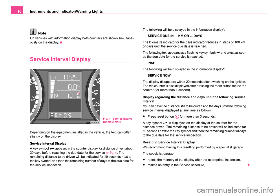
Service Interval Display
A key symbol
appears in the counter display for distance driven about
30 days before reaching the due date for the service ⇒fig. 4 . The
remaining distance to be driven will be indicated for 10 seconds next to
the key symbol and then the remaining number of days to the due date for
the service inspection. The following will be displayed in the information display*:
SERVICE DUE IN ... KM OR ... DAYS
The kilometre indicator or the days indicator reduces in steps of 100 km.
or days until the service due date is reached.
The following text appears as a flashing key symbol
and a text as soon
as the due date for the service is reached.
INSP
The following will be displayed in the information display*:
SERVICE NOW
The display disappears within 20 seconds after switching on the ignition.
The trip counter is also displayed after pressing the reset button for the trip
counter (for more than 1 second).
Display regarding the distance and days until the following service
interval
You can have the distance still to be driven and the days until the following
service interval displayed at any time as follows:
•Press reset button for more than 3 seconds.
A key symbol
is displayed on the display of the counter for the
distance driven. The remaining distance to be driven will be indicated for
10 seconds next to the key symbol and then the remaining number of days
to the due date for the service inspection.
Resetting Service Interval Display
We recommend having this resetting performed by a specialist garage.
The specialist garage:
•resets the memory of the display after the appropriate inspection,
•makes an entry in the Service schedule,
Fig. 4 Service Interval
Display: NoteA6
NKO 20 A05.book Page 16 Wednesday, June 21, 2006 1:42 PM
Page 18 of 274
Instruments and Indicator/Warning Lights17
Using the systemSafetyDriving TipsGeneral MaintenanceBreakdown assistanceTechnical Data
•affix the sticker with the entry of the following service interval to the
side of the dash panel on the driver's side.
The Service Interval Display can also be reset with the reset button as
follows:
•Switch off the ignition, press the reset button of the trip counter for
distance driven and hold it down.
•Switch the ignition on and release the reset button. Now turn the reset
button to the right. The service interval display is reset.
Caution
We recommend that you do not reset the Service Interval Display yourself
otherwise this can result in the service interval display being incorrectly
set, which may also result in problems with operation of your vehicle.
Note
•Never reset the display between service intervals otherwise this may
result in incorrect readouts.
•information is retained in the Service Interval Display also after the
battery of the vehicle is disconnected.
•it is necessary to re-code the Service Interval Display if a new instru-
ment cluster is installed during repair work. This work is carried out by a
specialist garage.
•The data displayed is the same after resetting the display with flexible
service intervals (QG1) using the reset button as that for a vehicle with
fixed service intervals (QG2). We therefore recommend having the
Service Interval Display reset only by a Škoda Service Partner who is
familiar with the procedure for resetting the display with a vehicle system
tester.
•Please refer to the brochure Service schedule for extensive informa-
tion about the service intervals.
Digital clock
A reset button is installed on the left below beside the speedom-
eter for adjusting the clock ⇒page 13, fig. 2 .
Set hours
– Turn the reset button to the left.
Setting minutes
– Turn the reset button to the right.
WARNING
The clock should not be adjusted while driving for safety reasons
but only when the vehicle is stationary.
Multi-functional indicator (onboard
computer)*
Introduction
The multi-functional indicator appears in the display ⇒page 18, fig. 5 or
in the information display ⇒page 22, fig. 8 depending on the equipment
fitted to your vehicle.
The multi-functional indicator offers you a range of useful information
A6
NKO 20 A05.book Page 17 Wednesday, June 21, 2006 1:42 PM
Page 23 of 274
Instruments and Indicator/Warning Lights
22
Information display*
Introduction
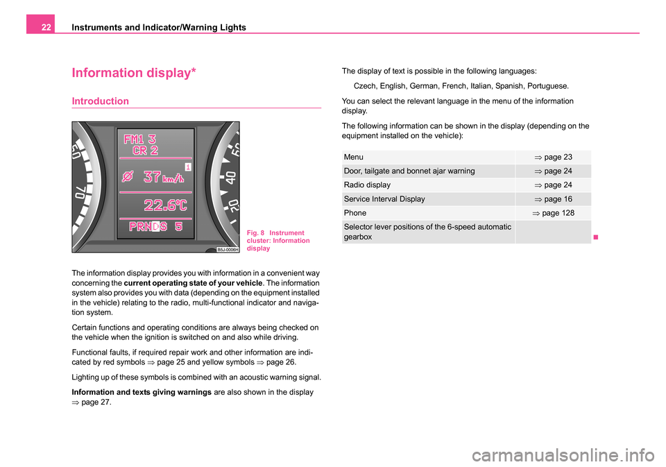
The information display provides you with information in a convenient way
concerning the current operating state of your vehicle . The information
system also provides you with data (depending on the equipment installed
in the vehicle) relating to the radio, multi-functional indicator and naviga-
tion system.
Certain functions and operating conditions are always being checked on
the vehicle when the ignition is switched on and also while driving.
Functional faults, if required repair work and other information are indi-
cated by red symbols ⇒page 25 and yellow symbols ⇒page 26.
Lighting up of these symbols is combined with an acoustic warning signal.
Information and texts giving warnings are also shown in the display
⇒ page 27. The display of text is possible in the following languages:
Czech, English, German, French, Italian, Spanish, Portuguese.
You can select the relevant language in the menu of the information
display.
The following information can be shown in the display (depending on the
equipment installed on the vehicle):
Fig. 8 Instrument
cluster: Information
display
Menu⇒ page 23
Door, tailgate and bonnet ajar warning⇒page 24
Radio display⇒page 24
Service Interval Display⇒page 16
Phone⇒page 128
Selector lever positions of the 6-speed automatic
gearbox
NKO 20 A05.book Page 22 Wednesday, June 21, 2006 1:42 PM
Page 25 of 274
Instruments and Indicator/Warning Lights
24
Door, tailgate and bonnet ajar warning
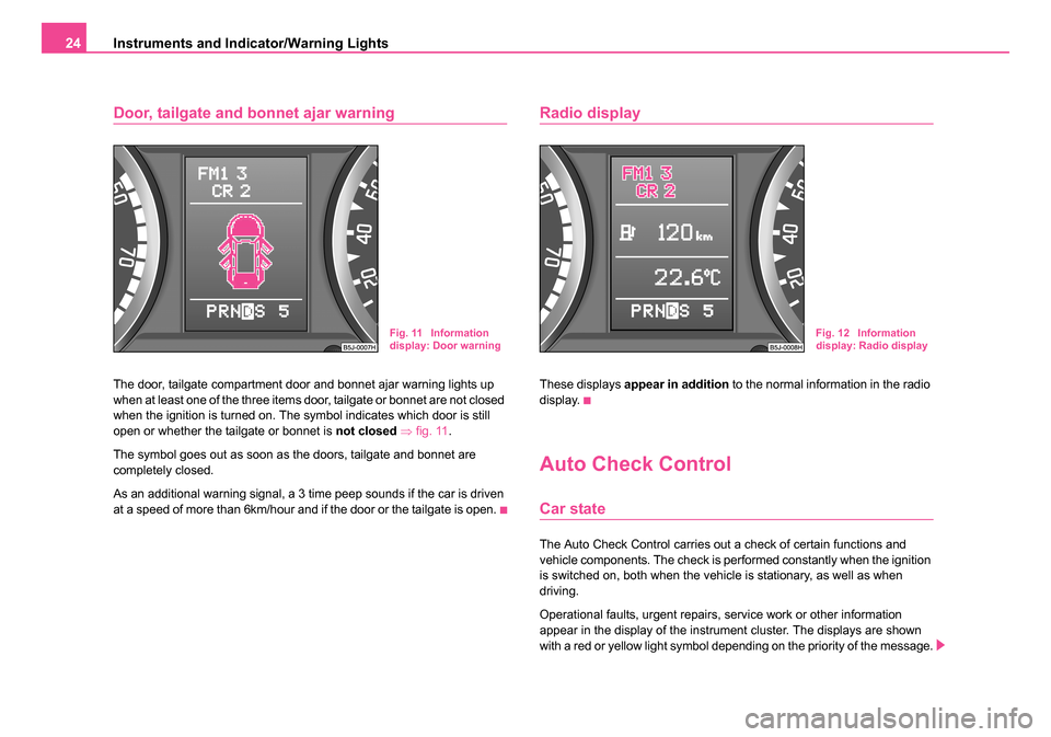
The door, tailgate compartment door and bonnet ajar warning lights up
when at least one of the three items door, tailgate or bonnet are not closed
when the ignition is turned on. The symbol indicates which door is still
open or whether the tailgate or bonnet is not closed ⇒ fig. 11 .
The symbol goes out as soon as the doors, tailgate and bonnet are
completely closed.
As an additional warning signal, a 3 time peep sounds if the car is driven
at a speed of more than 6km/hour and if the door or the tailgate is open.
Radio display
These displays appear in addition to the normal information in the radio
display.
Auto Check Control
Car state
The Auto Check Control carries out a check of certain functions and
vehicle components. The check is performed constantly when the ignition
is switched on, both when the vehicle is stationary, as well as when
driving.
Operational faults, urgent repairs, service work or other information
appear in the display of the instrument cluster. The displays are shown
with a red or yellow light symbol depending on the priority of the message.
Fig. 11 Information
display: Door warningFig. 12 Information
display: Radio display
NKO 20 A05.book Page 24 Wednesday, June 21, 2006 1:42 PM
Page 38 of 274
Instruments and Indicator/Warning Lights37
Using the systemSafetyDriving TipsGeneral MaintenanceBreakdown assistanceTechnical Data
There is a fault in the system if the warning light does not go out or comes
on or flashes while driving
⇒. This also applies if the warning light
does not come on after the ignition is switched on.
The following text will be displayed in the information display*:
AIRBAG FAULT
The functionality of the airbag system is also monitored electronically,
when one airbag has been switched off.
The passenger front airbag and also possibly the passenger side
airbag which have been switched off using the vehicle system tester:
•The warning light lights up for 3 seconds after switching on the igni-
tion and then flashes for 12 seconds afterwards in 2 second intervals.
The passenger front airbag and also possibly the passenger side
airbag which have been switched off using the switch (for switching
off airbags)* in the end face of the dash panel on the front passenger
side:
•The warning light comes on for 3 seconds after the ignition has
been switched on.
•Switching off airbags is indicated in the middle of the dash panel by the
lighting up of the indicator light (airbag switched off)
⇒ page 164.
WARNING
Have the airbag system checked immediately by a specialist
garage if a fault exists. Otherwise, there is a risk of the airbag not
being activated in the event of an accident.
Note
Further information about switching off airbags ⇒page 163, “Deactivating
an airbag”.
Diesel particle filter* (diesel engine)
In the diesel particle filter the resulting soot particles are
collected and burnt during the combustion of diesel fuel.
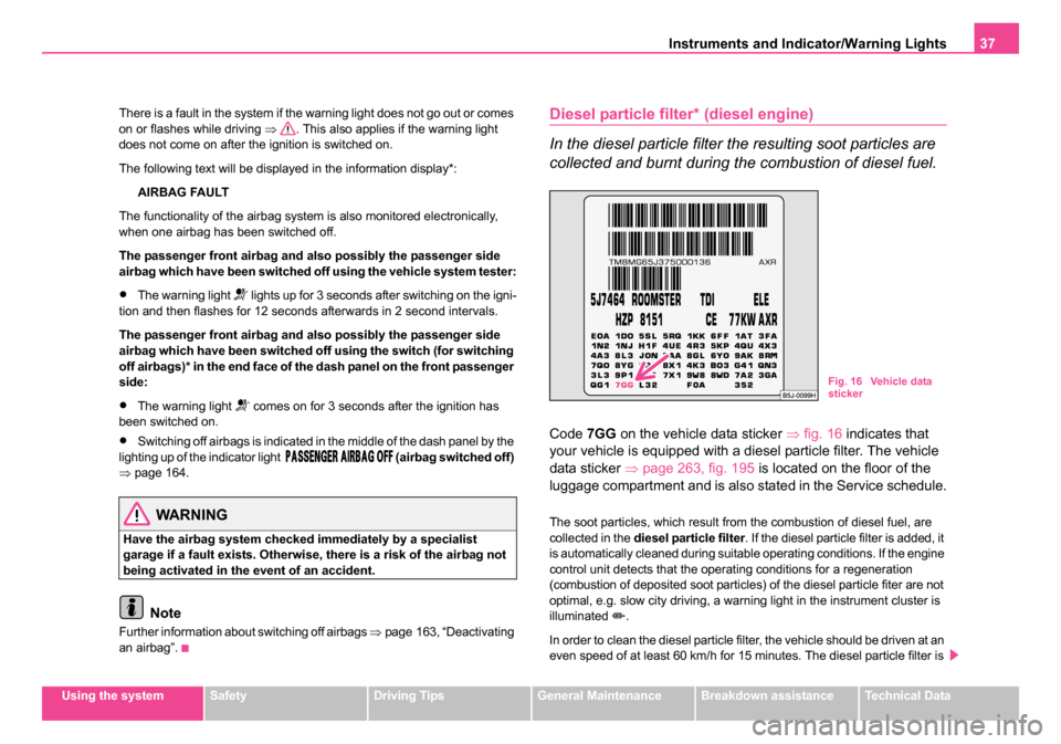
Code 7GG on the vehicle data sticker ⇒fig. 16 indicates that
your vehicle is equipped with a diesel particle filter. The vehicle
data sticker ⇒page 263, fig. 195 is located on the floor of the
luggage compartment and is also stated in the Service schedule.
The soot particles, which result from the combustion of diesel fuel, are
collected in the diesel particle filter . If the diesel particle filter is added, it
is automatically cleaned during suitable operating conditions. If the engine
control unit detects that the operating conditions for a regeneration
(combustion of deposited soot particles) of the diesel particle fiter are not
optimal, e.g. slow city driving, a warning light in the instrument cluster is
illuminated
.
In order to clean the diesel particle filter, the vehicle should be driven at an
even speed of at least 60 km/h for 15 minutes. The diesel particle filter is
Fig. 16 Vehicle data
sticker
NKO 20 A05.book Page 37 Wednesday, June 21, 2006 1:42 PM
Page 44 of 274
Unlocking and locking43
Using the systemSafetyDriving TipsGeneral MaintenanceBreakdown assistanceTechnical Data
After the car is locked with the deactivated safe securing system, the indi-
cator light flashes only after 30 seconds.
Indicator light in the driver's door on vehicles with anti-theft alarm
system
After locking the vehicle the indicator light flashes for 2 seconds fast, then
more slowly.
If the vehicle is locked and the safe securing system
⇒page 43 is not
operating, the indicator light in the driver door flashes for about 2 seconds
fast, goes out and starts to flash slowly after about 30 seconds.
If the indicator light first of all flashes fast for about 2 seconds, afterwards
lights up for about 30 seconds and then flashes slowly, there is a fault in
the system of the central locking or the interior monitor* ⇒page 50.
Contact a specialist garage to obtain assistance.
Convenience operation of windows
One can open and close the electrically powered windows when unlocking
and locking the vehicle ⇒page 53, “Window convenience operation”.
Opening a single door*
This function allows one to just unlock the driver's door. The other doors
remain locked and are only unlocked when the command is repeated. The
single door opening function can be first activated by recoding the control
unit of the central locking system. This work is undertaken by a Škoda
Service Partner can give you more information.
Automatic locking*
All the doors and the tailgate are locked automatically once the car
reaches a speed of about 15 km/h.
If the ignition key is withdrawn, the car is then automatically unlocked
again. In addition, it is possible for the driver to unlock the car by pressing
the central locking button
or by pulling the door opening lever. If you wish, your Škoda Service Partner can convert the central locking
system of your car to the automatic locking mode.
WARNING
•Locking the doors prevents involuntary opening in an excep-
tional situation (an accident). Locked doors prevent unwanted
entry into the vehicle from outside, for example at road crossings.
Locked doors do, however, make it more difficult for rescuers to
get into the vehicle in an emergency - danger to life!
Note
•In the event of an accident in which the airbags are deployed, the
locked doors are automatically unlocked in order to enable rescuers to
gain access to the vehicle.
•Only the front doors can be unlocked and locked using the key if the
central locking system fails. You can operate the rear door manually.
−Emergency locking of the door ⇒page 46.
Safe securing
The central locking system is equipped with a safe securing system.
Locking the vehicle from the outside causes the door locks to be automat-
ically blocked. The indicator light in the driver's door flashes. It is not
possible to open the doors with the door handle either from the inside or
from the outside. This acts as an effective deterrent for attempts to break
into your vehicle.
You can deactivate the safe securing system. This is done by locking the
vehicle with the key or radio-operated key twice within 2 seconds.
The safe securing system is again activated the next time the vehicle is
unlocked and locked again.
NKO 20 A05.book Page 43 Wednesday, June 21, 2006 1:42 PM
Page 164 of 274
Airbag system163
Using the systemSafetyDriving TipsGeneral MaintenanceBreakdown assistanceTechnical Data
Deactivating an airbag
Deactivating airbags
If any airbags have been deactivated, switch them on
again as soon as possible so that they are able to again
provide their proper protection.
There is the technical means installed within your vehicle to switch off the
front, side* or head airbag* (take out of commission).
This is why you should have the deactivation of the airbags carried out by
a specialist garage.
On vehicles equipped with the switch for deactivation of the airbags, you
can deactivate the front passenger airbag or passenger side airbag by
means of this switch ⇒page 164.
Deactivation of airbags is envisaged only for particular instances,
such as if:
•you must in exceptional cases use a child seat on the front
passenger seat where the child has its back to the direction of travel of the
vehicle (in some countries this must be in the direction of travel due to
other legal regulations applying) ⇒page 166, “Important safety informa-
tion regarding the use of child safety seats”
•you are not able to maintain the distance of at least 25 cm between
middle of steering wheel and chest, despite the driver seat being correctly
adjusted,
•special attachments are required in the area of the steering wheel
because of a physical disability,
•you have installed other seats (e.g. orthopaedic seats without side
airbags). Monitoring the airbag system
The functionality of the airbag system is also monitored electronically,
when one airbag has been switched off
If the airbag was switched off using diagnostic equipment:
•The airbag indicator light in the instrument cluster lights up for about 3
seconds after switching on the ignition and then flashes after that for about
12 seconds.
If the airbag was switched off using the airbag switch* on the side of
the dash panel:
•The airbag warning light comes on in the instrument cluster for about
3 seconds each time the ignition is switched on.
•Switching off airbags is indicated in the middle of the dash panel by the
lighting up of the indicator light ⇒ page 164, fig. 134 .
Note
Your Škoda Service Partner will be able to advise you whether national
legislation in your country allows airbags in your vehicle to be deactivated,
and which ones.
NKO 20 A05.book Page 163 Wednesday, June 21, 2006 1:42 PM