ECU SKODA ROOMSTER 2007 1.G User Guide
[x] Cancel search | Manufacturer: SKODA, Model Year: 2007, Model line: ROOMSTER, Model: SKODA ROOMSTER 2007 1.GPages: 248, PDF Size: 46.44 MB
Page 62 of 248
Seats and Stowage61
Using the systemSafetyDriving TipsGeneral MaintenanceBreakdown assistancePraktikTechnical Data
Folding the rear seats back into position
Locking seats and folding back into position
– If the seat is removed, first of all position it on the guide and lock the
seat ⇒page 60, fig. 56. Check for yourself that the seat is correctly
locked by pulling it up.
– Fold the seat into the horizontal posi tion until it is heard to lock. Check
for yourself that the seat is correctly locked by pulling it up.
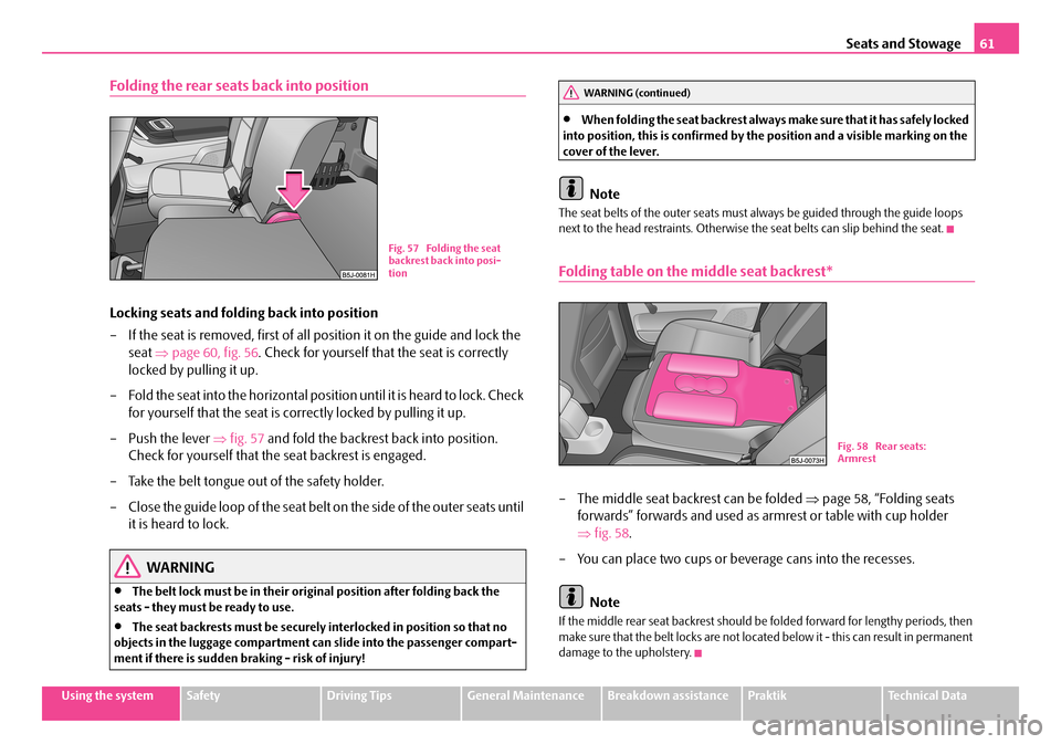
– Push the lever ⇒fig. 57 and fold the backrest back into position.
Check for yourself that the seat backrest is engaged.
– Take the belt tongue out of the safety holder.
– C l o s e th e g u id e l o o p o f t h e s ea t b el t o n th e s i de o f t h e o u te r s e a t s u n t il
it is heard to lock.
WARNING
•The belt lock must be in their original position after folding back the seats - they must be ready to use.
•The seat backrests must be securely interlocked in position so that no objects in the luggage compartment ca n slide into the passenger compart- ment if there is sudden braking - risk of injury!
•When folding the seat back rest always make sure that it has safely locked into position, this is confirmed by the position and a visible marking on the cover of the lever.
Note
The seat belts of the outer seats must always be guided through the guide loops next to the head restraints. Otherwise the seat belts can slip behind the seat.
Folding table on the middle seat backrest*
– The middle seat backrest can be folded ⇒page 58, “Folding seats
forwards” forwards and used as armrest or table with cup holder
⇒ fig. 58.
– You can place two cups or beverage cans into the recesses.
Note
If the middle rear seat backrest should be folded forward for lengthy periods, then make sure that the belt locks are not located below it - this can result in permanent damage to the upholstery.
Fig. 57 Folding the seat backrest back into posi-tion
WARNING (continued)
Fig. 58 Rear seats: Armrest
NKO A05R 20 MR08.book Page 61 Wednesday, March 28, 2007 9:42 AM
Page 63 of 248
Seats and Stowage62
Pedals
You should use only footmats which do not obstruct the movement of the pedals and have an anti -slip protection.
We recommend only to use footmats from Škoda genuine accessories offered by your Škoda dealer.
Operation of the pedals must not be hindered!
WARNING
•Greater pedal distances may be needed when there is a fault in the brake system.
•Do not place any footmats or other additional floor coverings in the area of the pedals in order to ensure that all the pedals can be fully depressed and are able to return unobstructed to their initial position - risk of accident!
•There must be no objects on the floor which could roll under the pedals. You would then no longer be able to apply the brakes, operate the clutch or accelerator - risk of accident!
luggage compartment
Loading the luggage compartment
Please observe the following in the inte rest of having good handling char-
acteristics of your vehicle:
– Distribute the items of luggage as evenly as possible.
– Place heavy objects as far forward as possible.
– Attach the items of luggage to the lashing eyes or the safety net*
⇒ page 63.
In the event of an accident, there is such a high kinetic energy which is produced by small and light objects that they can caus e severe injuries. The magnitude of the
kinetic energy depends on the speed at which the vehicle is travelling and on the weight of the object. The speed at which the vehicle is travelling is in this case the more significant factor.
Example: In the event of a frontal collision at a speed of 50 km/h, an unsecured object with a weight of 4.5 kg produces an energy, which corresponds to 20 times its own weight. This means that it results in a weight of approx. 90 kg. You can imagine the injuries that can occur, if this “bullet” is flying through the interior compartment and hits an occupant.
WARNING
•Store the objects in the luggage compartment and attach them to the lashing eyes.
•Loose objects in the passenger compartment can be thrown forward during a sudden manoeuvre or in case of an accident and can injure the occupants or other oncoming traffic. This risk is still increased, if the objects which are flying around are hit by a depl oyed airbag. In this case, the objects which are thrown back can injure the occupants - hazard.
•Please note that the handling properti es of your vehicle may be affected when transporting heavy objects as a result of the displacement of the centre of gravity. The speed and style of driving must be adjusted accord- ingly.
•The items carried in the luggage compar tment should be stored in such a way that no objects are able to slip forward if there are any sudden driving or braking manoeuvres undertaken - risk of injury!
•When transporting fastened objects which are sharp and dangerous in the luggage compartment enlarged by folding the rear seats forward or removing the rear seats, ensure the safety of the passengers transported on the other rear seats ⇒page 120, “Correct seated position for the occupants on the rear seats”.
•If the rear seats next to the folded forward seat are occupied, ensure maximum safety, e.g. by placing the goods to be transported in such a way that a folding back of the seat is pr evented in case of a rear collision.
•Never drive with the boot lid fully opened or slightly ajar otherwise exhaust gases may get into the interior of the vehicle - risk of poisoning!
NKO A05R 20 MR08.book Page 62 Wednesday, March 28, 2007 9:42 AM
Page 64 of 248
Seats and Stowage63
Using the systemSafetyDriving TipsGeneral MaintenanceBreakdown assistancePraktikTechnical Data
•On no account exceed the permissible axle loads and the permissible gross weight of the vehi cle - risk of accident!
•Never transport occupants in the luggage compartment.
Caution
Please ensure that the heating elements of the rear window heater are not damaged as a result of objects sliding in this area.
Note
•Tyre pressure must be adjusted to the load ⇒page 187, fig. 164.
•The air circulation in the interior of the car helps to prevent the windows from misting up. Stale air is diverted via the outlet nozzles into the luggage compartment below the bumper. Check for yourself that the outlet nozzles are not covered.
Fastening elements
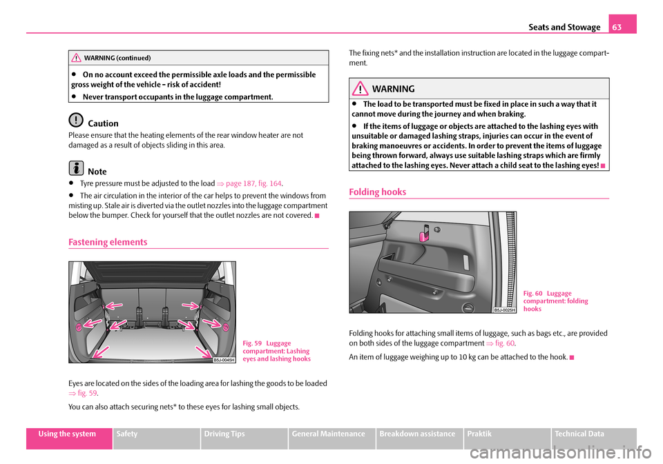
Eyes are located on the sides of the loading area for lashing the goods to be loaded ⇒ fig. 59.
You can also attach securing nets* to these eyes for lashing small objects.
The fixing nets* and the installation inst ruction are located in the luggage compart- ment.
WARNING
•The load to be transported must be fixed in place in such a way that it cannot move during the journey and when braking.
•If the items of luggage or objects ar e attached to the lashing eyes with unsuitable or damaged lashing straps, injuries can occur in the event of braking manoeuvres or accidents. In order to prevent the items of luggage being thrown forward, always use suit able lashing straps which are firmly attached to the lashing eyes. Never atta ch a child seat to the lashing eyes!
Folding hooks
Folding hooks for attaching small items of luggage, such as bags etc., are provided on both sides of the luggage compartment ⇒fig. 60.
An item of luggage weighing up to 10 kg can be attached to the hook.
WARNING (continued)
Fig. 59 Luggage compartment: Lashing eyes and lashing hooks
Fig. 60 Luggage compartment: folding hooks
NKO A05R 20 MR08.book Page 63 Wednesday, March 28, 2007 9:42 AM
Page 65 of 248
Seats and Stowage64
Fixing nets - Net programme*
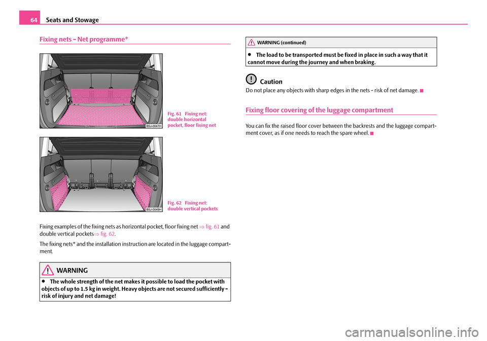
Fixing examples of the fixing nets as horizontal pocket, floor fixing net ⇒fig. 61 and double vertical pockets ⇒fig. 62.
The fixing nets* and the installation inst ruction are located in the luggage compart- ment.
WARNING
•The whole strength of the net makes it possible to load the pocket with objects of up to 1.5 kg in weight. Heavy objects are not secured sufficiently - risk of injury and net damage!
•The load to be transported must be fixed in place in such a way that it cannot move during the journey and when braking.
Caution
Do not place any objects with sharp edges in the nets - risk of net damage.
Fixing floor covering of the luggage compartment
You can fix the raised floor cover between the backrests and the luggage compart-ment cover, as if one needs to reach the spare wheel.
Fig. 61 Fixing net: double horizontal pocket, floor fixing net
Fig. 62 Fixing net: double vertical pockets
WARNING (continued)
NKO A05R 20 MR08.book Page 64 Wednesday, March 28, 2007 9:42 AM
Page 67 of 248
Seats and Stowage66
Bicycle carrier*
Install cross member
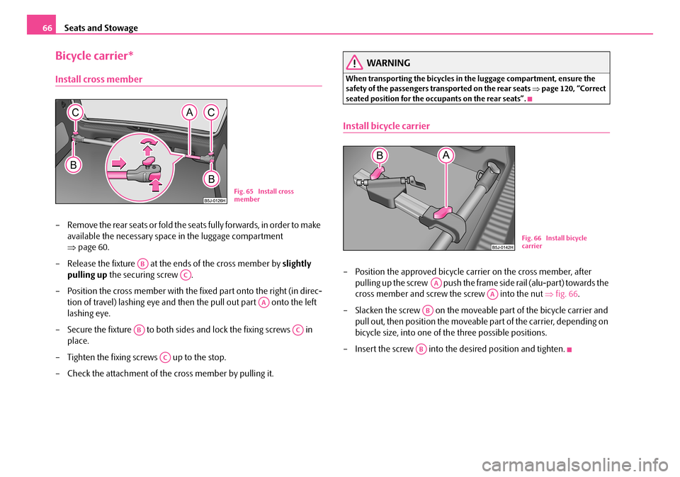
– Remove the rear seats or fold the seats fully forwards, in order to make
available the necessary space in the luggage compartment
⇒ page 60.
– Release the fixture at the ends of the cross member by slightly
pulling up the securing screw .
– Position the cross member with the fixed part onto the right (in direc-
tion of travel) lashing eye and then the pull out part onto the left
lashing eye.
– Secure the fixture to both sides and lock the fixing screws in
place.
– Tighten the fixing screws up to the stop.
– Check the attachment of the cross member by pulling it.
WARNING
When transporting the bicycles in the luggage compartment, ensure the safety of the passengers transported on the rear seats ⇒page 120, “Correct seated position for the occupants on the rear seats”.
Install bicycle carrier
– Position the approved bicycle carrier on the cross member, after
pulling up the screw push the frame side rail (alu-part) towards the
cross member and screw the screw into the nut ⇒fig. 66.
– Slacken the screw on the moveable part of the bicycle carrier and
pull out, then position the moveable part of the carrier, depending on
bicycle size, into one of the three possible positions.
– Insert the screw into the desired position and tighten.
Fig. 65 Install cross member
AB
AC
AA
ABAC
AC
Fig. 66 Install bicycle carrier
AA
AA
AB
AB
NKO A05R 20 MR08.book Page 66 Wednesday, March 28, 2007 9:42 AM
Page 68 of 248
Seats and Stowage67
Using the systemSafetyDriving TipsGeneral MaintenanceBreakdown assistancePraktikTechnical Data
Put bicycle into the bicycle carrier
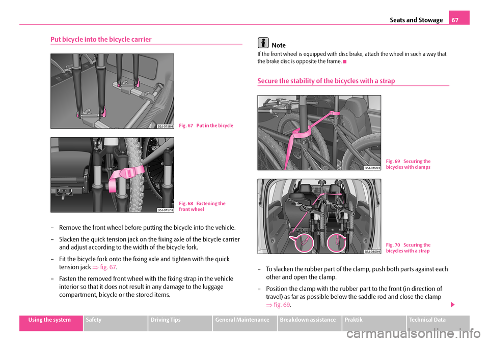
– Remove the front wheel before putting the bicycle into the vehicle.
– Slacken the quick tension jack on th e fixing axle of the bicycle carrier
and adjust according to the width of the bicycle fork.
– Fit the bicycle fork onto the fixing axle and tighten with the quick
tension jack ⇒fig. 67.
– Fasten the removed front wheel with the fixing strap in the vehicle
interior so that it does not resu lt in any damage to the luggage
compartment, bicycle or the stored items.
Note
If the front wheel is equipped with disc brake, attach the wheel in such a way that the brake disc is opposite the frame.
Secure the stability of the bicycles with a strap
– To slacken the rubber part of the cl amp, push both parts against each
other and open the clamp.
– Position the clamp with the rubber part to the front (in direction of
travel) as far as possible below the saddle rod and close the clamp
⇒ fig. 69.
Fig. 67 Put in the bicycle
Fig. 68 Fastening the front wheel
Fig. 69 Securing the bicycles with clamps
Fig. 70 Securing the bicycles with a strap
NKO A05R 20 MR08.book Page 67 Wednesday, March 28, 2007 9:42 AM
Page 77 of 248
Seats and Stowage76
Installing storage box
– In order to create a better access to the middle seat, fold one outer
backrest forwards.
– Fold the backrest of the middle seat forwards.
– Release the fixing hook from the secured position.
– Move the fixing holder ⇒page 75, fig. 88 from the rear between the
seat cushion and seat backrest, then align the seat backrest to the
vertical position.
– Move the fixing arms of the storage box into the locking eyes of the
fixing holder until they lock in place ⇒page 75, fig. 89.
– Check the interlock of both fixing arms by pulling on the storage
box.
Removing storage box
– Simultaneously press on each side of the storage box the red button in
direction opposite the seat backrest. The storage box releases.
– Fold the seat backrest forwards and remove the fixing holder, then
move the seat backrest into the original position.
WARNING
•Do not place any hot beverages into th e cup holder. If the vehicle moves, the hot beverages may spill - risk of scalding!
•Do not use any cups or beakers which are made of brittle material (e.g. glass, porcelain). You might be injured by them in the event of an accident.
•While driving, the storage box can only be used as an armrest in its closed position.
Caution
Do not open the beverages in the cup holder while driving. There is a risk of spilling e.g. when braking and therefore the electrical components or the seat upholstery can be damaged.
Storage compartments in the luggage compartment
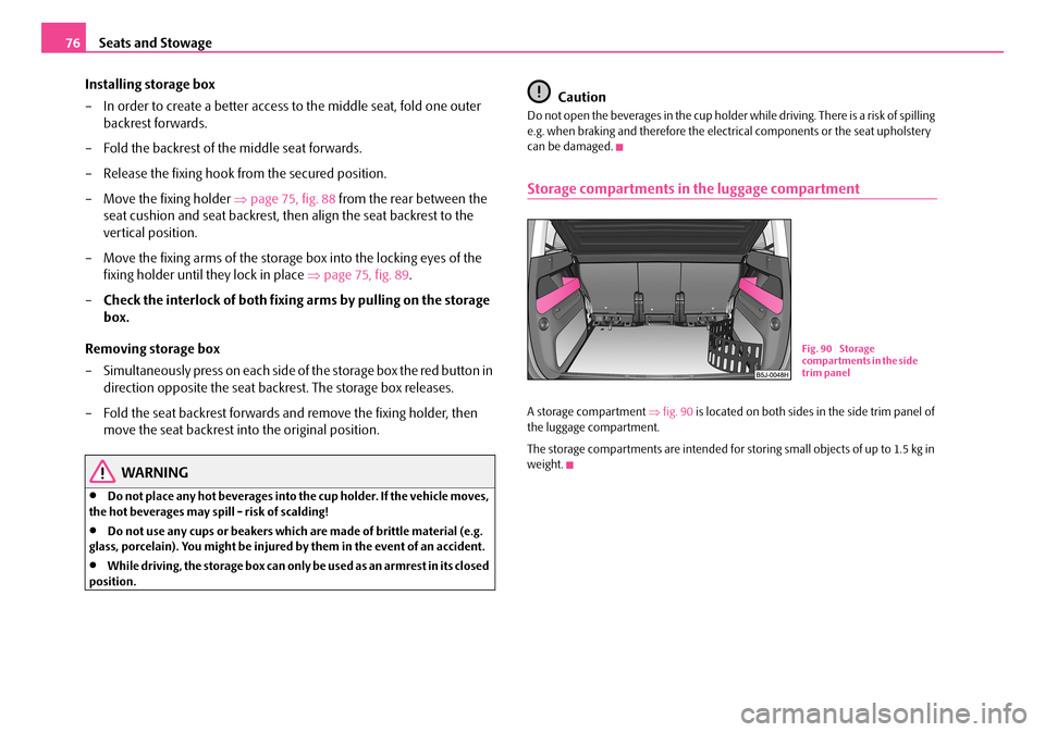
A storage compartment ⇒fig. 90 is located on both sides in the side trim panel of the luggage compartment.
The storage compartments are intended for storing small objects of up to 1.5 kg in weight.
Fig. 90 Storage compartments in the side trim panel
NKO A05R 20 MR08.book Page 76 Wednesday, March 28, 2007 9:42 AM
Page 106 of 248
Communication105
Using the systemSafetyDriving TipsGeneral MaintenanceBreakdown assistancePraktikTechnical Data
Caution
Taking the mobile phone out of the adapter during the call can lead to interruption of the connection. When taking out the mobile phone, the connection to the factory-fitted antenna is interrupted, this reduces the quality of the transmitting and receiving signal. This might result additionally in harmful radiation from the mobile phone in the interior of the ve hicle and the charging of the telephone battery is interrupted.
Note
•Please also refer to the additional instructions ⇒page 112, “Mobile phones and two-way radio systems”.
•Please contact your Škoda Service Partner if there are any points which are not clear.
•The voice control of the telephone is only possible for adapters with PTT button. Suitable adapters are available at a Škoda Service Partner.
Inserting the mobile phone and adapter
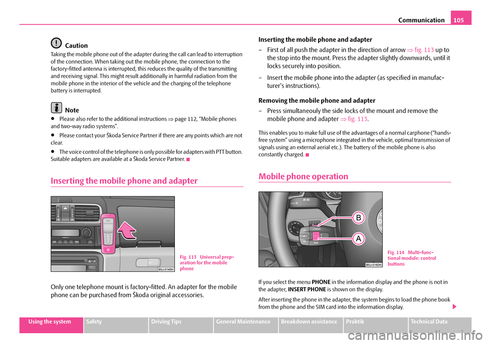
Only one telephone mount is factory-fitted. An adapter for the mobile
phone can be purchased from Škoda original accessories.
Inserting the mobile phone and adapter
– First of all push the adapter in the direction of arrow ⇒fig. 113 up to
the stop into the mount. Press the ad apter slightly downwards, until it
locks securely into position.
– Insert the mobile phone into the adapter (as specified in manufac-
turer's instructions).
Removing the mobile phone and adapter
– Press simultaneouly the side locks of the mount and remove the
mobile phone and adapter ⇒fig. 113.
This enables you to make full use of the advantages of a normal carphone (“hands- free system” using a microphone integrated in the vehicle, optimal transmission of signals using an external aerial etc.). The battery of the mobile phone is also constantly charged.
Mobile phone operation
If you select the menu PHONE in the information display and the phone is not in the adapter, INSERT PHONE is shown on the display.
After inserting the phone in the adapter, the system begins to load the phone book from the phone and the SIM card into the information display.
Fig. 113 Universal prep- aration for the mobile phone
Fig. 114 Multi-func-tional module: control buttons
NKO A05R 20 MR08.book Page 105 Wednesday, March 28, 2007 9:42 AM
Page 109 of 248
Communication108
•When entering an incorrect PIN code, the system indicates “The PIN is incor- rect ”.
•If the incorrect PIN code has been entered three times consecutively, the card is blocked. With the aid of the person al unblocking code PUK (Personal Unblock Key), the SIM card can be unblocked. The unblocking code can only be entered via the phone keypad and not through the voice control.
Example for entering the PIN code
You can interrupt the dialogue at any time by pressing the PTT button or with the voice command CANCEL.
Select number
– Press the PTT button.
– Give the command DIAL NUMBER after the signal tone.
After giving this command, the system requests the entry of a telephone number. The telephone number can be entered as an interconnected spoken row of digits (complete number), in the form of order of digits (separation through a brief voice pause) or through individually spoken digits. After each order of digits (separation through brief voice pause) the detected digits are repeated.
The digits zero to nine are permitted. The system detects no continuous digit combinations such as twenty-three, but only individually spoken digits (two, three).
When entering more than 20 digits, the system answers with voice response “ The number is too long ”.
Additionally for international calls a Plus (+) has to be entered in front of the 20 digits.
Example when entering a telephone number
You can interrupt the dialogue at any time by pressing the PTT button or with the voice command CANCEL.
Repeat last call
– Press the PTT button.
– Give the command REDIAL after the signal tone.
After giving this command, the last number selected via voice input is selected again.
Voice commandAnnouncement
ENTER PIN/PIN CODE“ The PIN please”
e.g. ZERO ONE TWO THREE“Zero One Two Three”
If no entry is put in, the following announcement is made after about 5 sec- onds.
“ Possible commands are: store, repeat, back, delete or more digits ”
STORE“The PIN is saved” (end of dialogue)
Voice commandAnnouncement
DIAL NUMBER“ The number please”
e.g. ZERO SIX ZERO THREE“Zero Six Zero Three”
If no entry is put in, the following announcement is made after about 5 sec- onds.
“ Possible commands are: dial, repeat, back, delete or more digits ”
FIVE SEVEN TWO“Five Seven Two”
DIAL“The number is being dialed”
NKO A05R 20 MR08.book Page 108 Wednesday, March 28, 2007 9:42 AM
Page 115 of 248
Communication114
Loading a CD
– Touch the button and guide the CD (compact disc) into the CD-
case . The CD is automatically loaded onto the next free position in
the CD-changer. The LED in the corresponding button stops
flashing.
Loading all CDs
– Hold the button pressed and guide all CDs one after the other into
the CD-case . The LEDs in the bu ttons are no longer flashing.
Loading a CD to one definite position
– Touch button . The LEDs in the buttons light up at the memory
spaces, which are already assigned and flash in the case of free
memory spaces.
– Touch the desired button and guide the CD into the CD-case .
Ejecting a CD
– Touch the button , in order to eject a CD. For assigned memory
spaces, now the LEDs light up in the buttons .
– Touch the corresponding button . The CD is ejected.
Ejecting all CDs
– Hold the button pressed for more than 2 seconds, in order to eject
the CDs. All CDs in the CD-cha nger are ejected consecutively.
Note
•Always guide the CD into the CD-cas e with the printed side pointing upwards.
•Never push the CD with force into the CD-case as the insertion is performed automatically.
•After loading a CD into the CD-changer, you must wait until the LED of the corresponding button lights up. Then th e CD-case is free to load the next CD.
•If you have selected a position, on which a CD is already located, this CD will be ejected. Take out the ejected CD and load the desired CD.
•The magazine can take up to six standard CDs (diameter 12 cm). Please do not use 8 cm “single CDs”!
•In order to avoid malfunctions of the chan ger, please never use a CD protective foil or stabilizer (obtainable on the market as CD-accessory).
•Described in this Owner's Manual are only the steps required for the operation of the CD-changer.
•You will find further information for this setting menu in the Radio Owner's Manual.
Tips for operating the CD-changer
Please pay attention to the following notes for operating the CD-changer.
•Only clean CDs without scratches and damages should be used, in order to guarantee a proper, high-quality CD-playback.
•Affix no labels to the CDs.
•Always store non-used CDs in the original folding box.
•Never expose CDs to direct sun rays.
•Use a soft, non-fluffy cloth to clean the CDs. Wipe the CD straight-lined from the middle to the outside. Strong dirt must be eliminated with usual CD-cleaner.
•Please never use liquids such as gasoline , paint thinner or disk cleaner, other- wise the surface of the CD could get damaged.
Precaution measures for laser equipment
Laser equipment is classified according to DIN IEC 76 (CO) 6/VDE 0837 in the safety categories 1 - 4.
The Škoda CD-changer correspond s to the safety category 1.
AC
AB
AD
AC
ABAD
ACAD
ADAB
AA
AD
AD
AA
AB
ADAB
NKO A05R 20 MR08.book Page 114 Wednesday, March 28, 2007 9:42 AM